EP0072267A1 - Suspension device for a tightly closing sliding door - Google Patents
Suspension device for a tightly closing sliding door Download PDFInfo
- Publication number
- EP0072267A1 EP0072267A1 EP82401204A EP82401204A EP0072267A1 EP 0072267 A1 EP0072267 A1 EP 0072267A1 EP 82401204 A EP82401204 A EP 82401204A EP 82401204 A EP82401204 A EP 82401204A EP 0072267 A1 EP0072267 A1 EP 0072267A1
- Authority
- EP
- European Patent Office
- Prior art keywords
- door
- suspension device
- fixed
- guide
- guide rail
- Prior art date
- Legal status (The legal status is an assumption and is not a legal conclusion. Google has not performed a legal analysis and makes no representation as to the accuracy of the status listed.)
- Granted
Links
Images

Classifications
-
- E—FIXED CONSTRUCTIONS
- E05—LOCKS; KEYS; WINDOW OR DOOR FITTINGS; SAFES
- E05D—HINGES OR SUSPENSION DEVICES FOR DOORS, WINDOWS OR WINGS
- E05D15/00—Suspension arrangements for wings
- E05D15/06—Suspension arrangements for wings for wings sliding horizontally more or less in their own plane
- E05D15/0621—Details, e.g. suspension or supporting guides
- E05D15/0626—Details, e.g. suspension or supporting guides for wings suspended at the top
- E05D15/063—Details, e.g. suspension or supporting guides for wings suspended at the top on wheels with fixed axis
-
- E—FIXED CONSTRUCTIONS
- E05—LOCKS; KEYS; WINDOW OR DOOR FITTINGS; SAFES
- E05D—HINGES OR SUSPENSION DEVICES FOR DOORS, WINDOWS OR WINGS
- E05D15/00—Suspension arrangements for wings
- E05D15/06—Suspension arrangements for wings for wings sliding horizontally more or less in their own plane
- E05D15/10—Suspension arrangements for wings for wings sliding horizontally more or less in their own plane movable out of one plane into a second parallel plane
- E05D15/1021—Suspension arrangements for wings for wings sliding horizontally more or less in their own plane movable out of one plane into a second parallel plane involving movement in a third direction, e.g. vertically
-
- E—FIXED CONSTRUCTIONS
- E05—LOCKS; KEYS; WINDOW OR DOOR FITTINGS; SAFES
- E05D—HINGES OR SUSPENSION DEVICES FOR DOORS, WINDOWS OR WINGS
- E05D15/00—Suspension arrangements for wings
- E05D15/06—Suspension arrangements for wings for wings sliding horizontally more or less in their own plane
- E05D15/10—Suspension arrangements for wings for wings sliding horizontally more or less in their own plane movable out of one plane into a second parallel plane
- E05D15/1042—Suspension arrangements for wings for wings sliding horizontally more or less in their own plane movable out of one plane into a second parallel plane with transversely moving carriage
- E05D2015/1055—Suspension arrangements for wings for wings sliding horizontally more or less in their own plane movable out of one plane into a second parallel plane with transversely moving carriage with slanted or curved track sections or cams
-
- E—FIXED CONSTRUCTIONS
- E05—LOCKS; KEYS; WINDOW OR DOOR FITTINGS; SAFES
- E05Y—INDEXING SCHEME RELATING TO HINGES OR OTHER SUSPENSION DEVICES FOR DOORS, WINDOWS OR WINGS AND DEVICES FOR MOVING WINGS INTO OPEN OR CLOSED POSITION, CHECKS FOR WINGS AND WING FITTINGS NOT OTHERWISE PROVIDED FOR, CONCERNED WITH THE FUNCTIONING OF THE WING
- E05Y2201/00—Constructional elements; Accessories therefore
- E05Y2201/60—Suspension or transmission members; Accessories therefore
- E05Y2201/622—Suspension or transmission members elements
- E05Y2201/638—Cams; Ramps
-
- E—FIXED CONSTRUCTIONS
- E05—LOCKS; KEYS; WINDOW OR DOOR FITTINGS; SAFES
- E05Y—INDEXING SCHEME RELATING TO HINGES OR OTHER SUSPENSION DEVICES FOR DOORS, WINDOWS OR WINGS AND DEVICES FOR MOVING WINGS INTO OPEN OR CLOSED POSITION, CHECKS FOR WINGS AND WING FITTINGS NOT OTHERWISE PROVIDED FOR, CONCERNED WITH THE FUNCTIONING OF THE WING
- E05Y2201/00—Constructional elements; Accessories therefore
- E05Y2201/60—Suspension or transmission members; Accessories therefore
- E05Y2201/622—Suspension or transmission members elements
- E05Y2201/684—Rails
-
- E—FIXED CONSTRUCTIONS
- E05—LOCKS; KEYS; WINDOW OR DOOR FITTINGS; SAFES
- E05Y—INDEXING SCHEME RELATING TO HINGES OR OTHER SUSPENSION DEVICES FOR DOORS, WINDOWS OR WINGS AND DEVICES FOR MOVING WINGS INTO OPEN OR CLOSED POSITION, CHECKS FOR WINGS AND WING FITTINGS NOT OTHERWISE PROVIDED FOR, CONCERNED WITH THE FUNCTIONING OF THE WING
- E05Y2201/00—Constructional elements; Accessories therefore
- E05Y2201/60—Suspension or transmission members; Accessories therefore
- E05Y2201/622—Suspension or transmission members elements
- E05Y2201/688—Rollers
- E05Y2201/69—Rollers having inclined axes
-
- E—FIXED CONSTRUCTIONS
- E05—LOCKS; KEYS; WINDOW OR DOOR FITTINGS; SAFES
- E05Y—INDEXING SCHEME RELATING TO HINGES OR OTHER SUSPENSION DEVICES FOR DOORS, WINDOWS OR WINGS AND DEVICES FOR MOVING WINGS INTO OPEN OR CLOSED POSITION, CHECKS FOR WINGS AND WING FITTINGS NOT OTHERWISE PROVIDED FOR, CONCERNED WITH THE FUNCTIONING OF THE WING
- E05Y2800/00—Details, accessories and auxiliary operations not otherwise provided for
- E05Y2800/26—Form, shape
- E05Y2800/298—Form, shape having indentations
-
- E—FIXED CONSTRUCTIONS
- E05—LOCKS; KEYS; WINDOW OR DOOR FITTINGS; SAFES
- E05Y—INDEXING SCHEME RELATING TO HINGES OR OTHER SUSPENSION DEVICES FOR DOORS, WINDOWS OR WINGS AND DEVICES FOR MOVING WINGS INTO OPEN OR CLOSED POSITION, CHECKS FOR WINGS AND WING FITTINGS NOT OTHERWISE PROVIDED FOR, CONCERNED WITH THE FUNCTIONING OF THE WING
- E05Y2900/00—Application of doors, windows, wings or fittings thereof
- E05Y2900/10—Application of doors, windows, wings or fittings thereof for buildings or parts thereof
- E05Y2900/13—Application of doors, windows, wings or fittings thereof for buildings or parts thereof characterised by the type of wing
- E05Y2900/132—Doors
Definitions
- the present invention relates to watertight sliding doors and their suspension devices, such doors being used, in particular for enclosures in which a determined temperature and / or atmosphere must be maintained.
- the door support means essentially consists of a traction arm, a first end of which cooperates with a first guide member secured to the wall, with respect to which it can move angularly and in translation and the other end of which supports the door itself in oscillating fashion.
- the device also comprises a second guide rail fixed to the wall, the guide surface of which delimits at least one ramp or a notch with which at least one roller or rolling or sliding element cooperates carried by means of supporting the door.
- the angle formed by the traction arm with the horizontal allows when the roller located on the second guide rail falls into a notch, to generate a force for applying the door on the frame equal to 1.4 to 1.7 times the weight of the door, which naturally favors obtaining a good seal.
- This improvement consists in replacing the two guide rails by a C-shaped profile fixed against the wall, the edge of the lower wing of the C forming the surface of said second guide rail, and the upper part of the C delimiting a surface of bearing diri inwardly of the profile and constituting said first guide rail.
- the object of the present invention is to provide improvements to the above devices with a view to obtaining a more compact device, greater closing efficiency, and a better external appearance, while reducing its cost price.
- the present invention relates to a device for suspending a watertight sliding door.
- a guide rail having a cross section in the general shape of C, fixed to a wall and delimiting two guide surfaces, one of which comprises at least one ramp or a notch with which at least one roller or other rolling element cooperates or sliding carried by door support means and the other of which cooperates with at least one roller or other rolling element or sliding carried by a swing arm connected to the door, characterized in that the or each swing arm is disposed entirely inside the C-section rail and works in compression.
- the ends of the C formed by the lower and upper edges of the C are arranged in an approximately horizontal plane and the guide surfaces situated at said ends of the C are approximately perpendicular to each other.
- the door is mounted on fittings connected in an oscillating manner to the compression arm and which support the or each rolling or sliding element cooperating with the first guide surface.
- the compression arms are inclined to the horizontal by an angle less than 45 ° when the door is in the closed position.
- Door P and its suspension devices are shown diagrammatically in FIGS. 1 and 2A, 2B.
- the door P is suspended from a guide rail 1 by means of suspension devices S each comprising two rollers G 1 and G 2 which ensure the longitudinal movement of the door, by rolling on the guide rail.
- suspension devices S each comprising two rollers G 1 and G 2 which ensure the longitudinal movement of the door, by rolling on the guide rail.
- notches 2 In the guide rail are provided notches 2 into which the rollers G 1 fall when the door is in the closed position of FIG. 2A.
- each suspension device S and its cooperation with the door P and the guide rail are shown in Fig.3 to 5.
- the door is shown in the open position in Fig.3. It is shown in the closed position resting on its sealing beads B in Fig. 4.
- the guide rail 1 is constituted by a C-shaped section lying down, open downwards, and kept applied to the wall M by a first wing la, by means of a fitting 4 and a wing 5a of a bracket 5, the assembly being tightened by a screw 6 which passes through them and is screwed into the wall M.
- the guide rail 1 is also fixed by its upper core 1b to the upper wing 5b of the bracket 5 by means of a fixing means 7, so that the core 1b is planar and approximately horizontal. .
- the free end 1c of the wing 1a of the rail 1 is folded obliquely towards the interior of the C and forms an angle close to 45 ° with the horizontal so as to constitute a plane guide surface 8 internal to the profile C.
- the guide surface 8 and the wing also have it Lement in two predetermined locations the notches 2 which can be seen in Fig.4.
- the wing of C opposite the wall M comprises two parts Id and forming between them an obtuse angle.
- the part Id is adjacent to the core Ib.
- the part it extends parallel to the wing la and ends at its free end by a flange 1f directed towards the inside of the profile, this flange delimiting in the angle formed internally with the adjacent part 1c, a rolling surface 9 of circular arc section located inside the guide rail 1 and thus constituting a second guide surface whose mean plane is approximately perpendicular to the guide surface 8.
- the oblique wing 13a also supports a roller support device G 2 composed of two brackets 15 and 16, (Fig.5) with perpendicular wings.
- the wings 15a and 16a of these brackets are fixed to the wing 13a by means of clamping means 17 and 18.
- the other wings 15b and 16b are held apart apart from one another by a spacer 19 and a rod 20, the longitudinal axes of the spacer 19 and of the rod 20 being arranged parallel to the longitudinal axis of the guide rail 1.
- On the rod 20 is articulated the core 21a of a compression arm 21 in the form of yoke between the legs 21b and 21c from which pivots, on a rod 22 perpendicular to the rod 20, the roller G 2 .
- This roller G 2 rests on the rolling surface 9 and has a toroidal peripheral surface, which allows an angular displacement of the axis of the roller G 2 relative to the surface 9.
- the rod 20 is located above the rollers G and G 2 , near the core 1b of C; the mean planes of the two rollers intersect in the vicinity of this rod and are inclined at approximately the same angle on the vertical.
- the device When the door is in translation position, that is to say in partial or total opening position, the device has the configuration shown in Fig.3.
- the rollers G 1 , G 2 roll respectively along their guide path 8 and 9.
- the rollers G 1 fall into the notches 2 wing Ia, causing the door to move to the floor and to the wall.
- the angle formed by the mean planes of the rollers G 1 and G 2 increases by a value d of about 1 5 ° to take the position shown in Fig.4 where we can see that the rollers G 2 have tilted around their fulcrum on the rolling surface 9.
- Fig.l one can examine how the forces are broken down when the door is in the closed position.
- the weight Po of the door, transmitted by the profile 13, is exerted on the rod 20. Its line of action, from this rod passes between the rollers G 1 and G 2 . If it is assumed that the rolling surface 8 practically does not intervene in the transmission of forces, which is actually the case in reality due to the support of the beads B on the wall M, the weight Po of the door can be broken down into a component P T directed along the compression arm 21 and a horizontal component P H.
- the door In its lower part, the door is guided by rollers 22 of conical shape and vertical axis, whose generator closest to the wall is inclined relative to vertical to the above-mentioned angle ⁇ . In this way, the reaction exerted by the wall on the lower part of the door is absorbed by the lower guide rollers.
- the compression arm 21 makes an angle ⁇ with the horizontal when the door is in the closed position and an angle ⁇ + ⁇ when the latter is in the open position.
- the angle of inclination of the compression arm with the horizontal is therefore minimal when the door is in the closed position, and this situation is naturally favorable to greater efficiency of the closing force of the door. It will be noted that with the device of the invention as just described, it is always possible to obtain any values of 3 between 0 and 45 ° by increasing for example the distance between the two wings of the C and / or by raising the edge If of the same profile.
Abstract
La présente invention concerne un dispositif de suspension d'une porte étanche coulissante. Le dispositif comprend un rail de guidage (1) ayant une section transversale en forme générale de C, fixé sur un mur (M) et délimitant deux surfaces de guidage (8, 9) dont l'une (8) comporte une encoche (2) avec laquelle coopère au moins un galet (G1) ou autre elément de roulement ou glissement porté par des moyens (13) de support de la porte et dont l'autre coopère avec au moins un galet (G2) ou autre élément de roulement ou glissement porté par un bras (21) oscillant relié à la porte (P), caractérisé en ce que le ou chaque bras oscillant est disposé entièrement à l'intérieur du rail (1) à section en C et travaille en compression.The present invention relates to a device for suspending a sliding waterproof door. The device comprises a guide rail (1) having a cross section in the general shape of C, fixed to a wall (M) and delimiting two guide surfaces (8, 9) one of which (8) has a notch (2 ) with which cooperates at least one roller (G1) or other rolling element or sliding carried by means (13) for supporting the door and the other of which cooperates with at least one roller (G2) or other rolling element or sliding carried by an oscillating arm (21) connected to the door (P), characterized in that the or each oscillating arm is disposed entirely inside the rail (1) with a C section and works in compression.
Description
La présente invention concerne les portes étanches coulissantes et leurs dispositifs de suspension, de telles portes étant utilisées, notamment pour des enceintes dans lesquelles doivent être maintenues une température et/ou une atmosphère déterminées.The present invention relates to watertight sliding doors and their suspension devices, such doors being used, in particular for enclosures in which a determined temperature and / or atmosphere must be maintained.
Un dispositif de suspension d'une porte étanche coulissante de construction simple et peu coûteuse permettant d'obtenir une force de fermeture de la porte sensiblement accrue par rapport à ce qui était déjà obtenu dans les systèmes de l'art antérieur est décrit dans la demande de brevet n° 72 42 370. Dans ce dispositif, le moyen de support de la porte est essentiellement constitué par un bras de traction dont une première extrémité coopère avec un premier organe de guidage solidaire du mur, par rapport auquel il peut se déplacer angulairement et en translation et dont l'autre extrémité supporte de façon oscillante la porte proprement dite.A device for suspending a sealed sliding door of simple and inexpensive construction making it possible to obtain a closing force of the door significantly increased compared to what was already obtained in the systems of the prior art is described in the application. Patent No. 72 42 370. In this device, the door support means essentially consists of a traction arm, a first end of which cooperates with a first guide member secured to the wall, with respect to which it can move angularly and in translation and the other end of which supports the door itself in oscillating fashion.
Le dispositif comprend également un deuxième rail de guidage fixé au mur, dont la surface de guidage délimite au moins une rampe ou une encoche avec laquelle coopère au moins un galet ou élément de roulement ou de glissement porté par des moyens de support de la porte.The device also comprises a second guide rail fixed to the wall, the guide surface of which delimits at least one ramp or a notch with which at least one roller or rolling or sliding element cooperates carried by means of supporting the door.
Toujours dans ce dispositif, l'angle formé par le bras de traction avec l'horizontale permet lorsque le galet situé sur le deuxième rail de guidage tombe dans une encoche, d'engendrer une force d'application de la porte sur le dormant égale à 1,4 jusqu'à 1,7 fois le poids de la porte, ce qui naturellement est favorable à l'obtention d'une bonne étanchéité.Also in this device, the angle formed by the traction arm with the horizontal allows when the roller located on the second guide rail falls into a notch, to generate a force for applying the door on the frame equal to 1.4 to 1.7 times the weight of the door, which naturally favors obtaining a good seal.
Un perfectionnement à ce dispositif est décrit dans le certificat d'addition n° 76 24 558.An improvement to this device is described in addition certificate n ° 76 24 558.
Ce perfectionnement consiste à remplacer les deux rails de guidage par un profilé en forme de C fixé contre le mur, le bord de l'aile inférieure du C formant la surface dudit deuxième rail de guidage, et la partie supérieure du C délimitant une surface de roulement dirigée vers l'intérieur du profilé et constituant ledit premier rail de guidage. Cette solution simplifie notablement la fabrication du dispositif de suspension et en diminue par conséquent le prix de revient.This improvement consists in replacing the two guide rails by a C-shaped profile fixed against the wall, the edge of the lower wing of the C forming the surface of said second guide rail, and the upper part of the C delimiting a surface of bearing diri inwardly of the profile and constituting said first guide rail. This solution significantly simplifies the manufacture of the suspension device and consequently reduces the cost price.
Aussi perfectionné que soit ce dernier dispositif, il présente toutefois les inconvénients suivants. En premier lieu, la position du galet d'extrémité du bras de traction qui est toujours au dessus de celle du galet roulant sur l'aile inférieure du C, impose une distance vers le haut non négligeable entre le bord de l'aile inférieur du C et sa partie supérieure. Ceci se traduit par un manque de compacité de l'ensemble galets, bras de traction et profilé en C, qui a pour conséquence de rendre trop important l'espace qui doit être réservé au profilé en C au-dessus de la porte étanche, la réservation de cet- espace se faisant naturellement au détriment de la hauteur disponible pour la porte elle-même.As sophisticated as this latter device is, it nevertheless has the following drawbacks. Firstly, the position of the end roller of the traction arm which is always above that of the roller running on the lower wing of the C, imposes a significant upward distance between the edge of the lower wing of the C and its upper part. This results in a lack of compactness of the rollers, traction arm and C-profile assembly, which has the consequence of making too much space which must be reserved for the C-profile above the watertight door, the reservation of this space takes place naturally at the expense of the height available for the door itself.
En deuxième lieu l'angle d'inclinaison formé par le bras de traction avec l'horizontale, lorsque la porte est en position ouverte augmente d'une quantité α lorsque la porte passe en position fermée, ce qui limite l'efficacité maximum de la force de fermeture à celle obtenue pour l'angle résiduelSecondly the angle of inclination formed by the traction arm with the horizontal, when the door is in the open position increases by an amount α when the door passes in the closed position, which limits the maximum efficiency of the closing force to that obtained for the residual angle
Enfin, le point d'articulation du bras de traction sur la porte se trouvant à l'extérieur du profilé en forme de C expose les galets de suspension aux poussières, ce qui nécessite le montage d'un profilé extérieur ou carter de protection qui augmente d'autant le prix de revient de l'ensemble.Finally, the point of articulation of the traction arm on the door located outside the C-shaped profile exposes the suspension rollers to dust, which requires the mounting of an outer profile or protective casing which increases all the more the cost price of the whole.
Le but de la présente invention est d'apporter des perfectionnements aux dispositifs ci-dessus en vue d'obtenir un dispositif plus compact, une plus grande efficacité de fermeture, et un meilleur aspect extérieur, tout en réduisant son prix de revient.The object of the present invention is to provide improvements to the above devices with a view to obtaining a more compact device, greater closing efficiency, and a better external appearance, while reducing its cost price.
A cet effet, la présente invention a pour objet un dispositif de suspension d'une porte étanche coulissante comprenant un rail de guidage ayant une section transversale en forme générale de C, fixé sur un mur et délimitant deux surfaces de guidage dont l'une comporte au moins une rampe ou une encoche avec laquelle coopère au moins un galet ou autre élément de roulement ou glissement porté par des moyens de support de la porte et dont l'autre coopère avec au moins un galet ou autre élément de roulement ou glissement porté par un bras oscillant relié à la porte, caractérisé en ce que le ou chaque bras oscillant est disposé entièrement à l'intérieur du rail à section en C et travaille en compression.To this end, the present invention relates to a device for suspending a watertight sliding door. comprising a guide rail having a cross section in the general shape of C, fixed to a wall and delimiting two guide surfaces, one of which comprises at least one ramp or a notch with which at least one roller or other rolling element cooperates or sliding carried by door support means and the other of which cooperates with at least one roller or other rolling element or sliding carried by a swing arm connected to the door, characterized in that the or each swing arm is disposed entirely inside the C-section rail and works in compression.
Suivant une autre caractéristique de l'invention, les extrémités du C formées par les bords inférieur et supérieur du C sont disposées dans un plan à peu près horizontal et les surfaces de guidage situées auxdites extrémités du C sont à peu près perpendiculaires entre elles.According to another characteristic of the invention, the ends of the C formed by the lower and upper edges of the C are arranged in an approximately horizontal plane and the guide surfaces situated at said ends of the C are approximately perpendicular to each other.
Suivant un mode de réalisation préféré de l'invention, la porte est montée sur des ferrures reliées de façon oscillante au bras de compression et qui supportent le ou chaque élément de roulement ou de glissement coopérant avec la première surface de guidage.According to a preferred embodiment of the invention, the door is mounted on fittings connected in an oscillating manner to the compression arm and which support the or each rolling or sliding element cooperating with the first guide surface.
De préférence, les bras de compression sont inclinés sur l'horizontale d'un angle inférieur à 45° lorsque la porte est en position de fermeture.Preferably, the compression arms are inclined to the horizontal by an angle less than 45 ° when the door is in the closed position.
L'invention sera mieux comprise à l'aide de la description qui va suivre donnée à titre d'exemple et faite en se référant aux dessins annexés, sur lesquels :
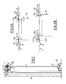
- - la Fig.l est une vue schématique montrant la décomposition des forces lorsque la porte est en équilibre sur le rail de guidage;
- - les Fig.2A et 2B représentent de façon schématique les positions de la porte par rapport au rail de guidage dans les positions respectivement fermée et ouverte;
- - la Fig.3 est une vue en coupe du dispositif de suspension suivant la ligne 3-3 de la Fig.2B;
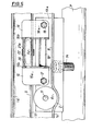
- - la Fig.4 est une vue en coupe du dispositif de suspension suivant la ligne 4-4 de la Fig.2A;
- - la Fig.5 est une vue en coupe du dispositif de suspension suivant la ligne 5-5 de la Fig.4.
- - Fig.l is a schematic view showing the breakdown of forces when the door is balanced on the guide rail;
- - Fig.2A and 2B schematically represent the positions of the door relative to the guide rail in the closed and open positions respectively;
- - Fig.3 is a sectional view of the device suspension along line 3-3 of Fig.2B;
- - F ig.4 is a sectional view of the suspension device along line 4-4 of Fig.2A;
- - Fig.5 is a sectional view of the suspension device along line 5-5 of Fig.4.
La porte P et ses dispositifs de suspension sont représentés de façon schématique aux Fig. 1 et 2A,2B. Sur ces figures, la porte P est suspendue à un rail de guidage 1 par l'intermédiaire de dispositifs de suspension S comprenant chacun deux galets G1 et G2 qui assurent le déplacement longitudinal de la porte, par roulement sur le rail de guidage. Dans le rail de guidage sont ménagées des encoches 2 dans lesquelles tombent les galets G1 lorsque la porte est dans la position fermée de la Fig. 2A.Door P and its suspension devices are shown diagrammatically in FIGS. 1 and 2A, 2B. In these figures, the door P is suspended from a
Les détails de réalisation de chaque dispositif de suspension S et sa coopération avec la porte P et le rail de guidage sont représentés aux Fig.3 à 5. La porte est représentée en position ouverte sur la Fig.3. Elle est représentée en position fermée reposant sur ses bourrelets d'étanchéité B à la Fig.4.The details of embodiment of each suspension device S and its cooperation with the door P and the guide rail are shown in Fig.3 to 5. The door is shown in the open position in Fig.3. It is shown in the closed position resting on its sealing beads B in Fig. 4.
Sur ces figures, le rail de guidage 1 est constitué par un profilé en forme de C couché, ouvert vers le bas, et maintenu appliqué au mur M par une première aile la, par l'intermédiaire d'une ferrure 4 et d'une aile 5a d'une équerre 5, l'ensemble étant serré par une vis 6 qui les traverse et est vissée dans le mur M.In these figures, the
Le rail de guidage 1 est également fixé par son âme supérieure lb à l'aile supérieure 5b de l'équerre 5 par l'intermédiaire d'un moyen de fixation 7, de façon que l'âme lb soit plane et à peu près horizontale. L'extrémité libre le de l'aile la du rail 1 est repliée obliquement vers l'intérieur du C et forme un angle voisin de 45° avec l'horizontale de façon à constituer une surface de guidage plane 8 interne au profilé C.The
La surface de guidage 8 et l'aile le présentent également en deux emplacements prédéterminés les encoches 2 que l'on peut voir sur la Fig.4. L'aile du C opposée au mur M comprend deux parties Id et le formant entre elles un angle obtus. La partie Id est adjacente à l'âme Ib. La partie le s'étend parallèlement à l'aile la et se termine à son extrémité libre par un rebord 1f dirigé vers l'intérieur du profilé, ce rebord délimitant dans l'angle formé intérieurement avec la partie adjacente le, une surface de roulement 9 à section en arc de cercle située à l'intérieur du rail de guidage 1 et constituant ainsi une deuxième surface de guidage dont le plan moyen est à peu près perpendiculaire à la surface de guidage 8. Sur la surface de guidage 8 roule le galet G monté fou autour d'une bague 10 qui est fixée par un boulon 11 à une aile supérieure oblique 13a d'un profilé 13 en V. L'aile inférieure 13b du profilé 13 est à peu près horizontale et fixée au bord supérieur de la porte P à l'aide d'un moyen de fixation 14.The
L'aile oblique 13a supporte également un dispositif support du galet G2 composé de deux équerres 15 et 16, (Fig.5) à ailes perpendiculaires. Les ailes 15a et 16a de ces équerres sont fixées sur l'aile 13a à l'aide de moyens de serrage 17 et 18. Les autres ailes 15b et 16b sont maintenues écartées parallèlement l'une à l'autre par une entretoise 19 et une tige 20, les axes longitudinaux de l'entretoise 19 et de la tige 20 étant disposés parallèlement à l'axe longitudinal du rail de guidage 1. Sur la tige 20 est articulée l'âme 21a d'un bras de compression 21 en forme de chape entre les jambes 21b et 21c duquel tourillonne, sur une tige 22 perpendiculaire à la tige 20, le galet G2. Ce galet G2 repose sur la surface de roulement 9 et possède une surface périphérique torique, ce qui permet un déplacement angulaire de l'axe du galet G2 par rapport à la surface 9. La tige 20 se trouve au-dessus des galets G et G2, près de l'âme 1b du C; les plans moyens des deux galets se coupent au voisinage de cette tige et sont inclinés à peu près d'un même angle sur la verticale.The
Le fonctionnement du dispositif est décrit ci-après. Lorsque la porte est en position de translation, c'est-à-dire en position d'ouverture partielle ou totale, le dispositif a la configuration représentée à la Fig.3. Lors de la translation de la porte, les galets G1, G2 roulent respectivement le long de leur chemin de guidage 8 et 9. Lorsque la porte parvient au voisinage ou dans sa position de fermeture, les galets G1 tombent dans les encoches 2 de l'aile Ia, ce qui provoque un déplacement de la porte vers le sol et vers le mur. Lors de ce déplacement, l'angle formé par les plans moyens des galets G1 et G2 augmente d'une valeur d d'environ 15° pour prendre la position représentée sur la Fig.4 où l'on peut voir que les galets G2 ont basculé autour de leur point d'appui sur la surface de roulement 9.The operation of the device is described below. When the door is in translation position, that is to say in partial or total opening position, the device has the configuration shown in Fig.3. During the translation of the door, the rollers G 1 , G 2 roll respectively along their
En se reportant à la Fig.l, on peut examiner comment s'effectue la décomposition des forces lorsque la porte est en position de fermeture. Le poids Po de la porte, transmis par le profilé 13, s'exerce sur la tige 20. Sa ligne d'action, à partir de cette tige passe entre les galets G1 et G2. Si l'on suppose que la surface de roulement 8 n'intervient pratiquement pas dans la transmission des efforts, ce qui est effectivement le cas dans la réalité du fait de l'appui des bourrelets B sur le mur M, le poids Po de la porte peut se décomposer en une composante PT dirigée suivant le bras de compression 21 et une composante horizontale PH. On voit sur la Fig.l que si β représente l'angle que forme le bras de compression par rapport à l'horizontale lorsque la porte se trouve en position de fermeture, la composante horizontale PH du poids qui est égale à Po, est supérieure à Po si l'on prend la Tgβ précaution de choisir un angle βinférieur à 45°.Referring to Fig.l, one can examine how the forces are broken down when the door is in the closed position. The weight Po of the door, transmitted by the
Dans sa partie inférieure, la porte est guidée par des galets 22 de forme conique et d'axe vertical, dont la génératrice la plus proche du mur est inclinée par rapport à la verticale de l'angle β précité. De la sorte, la réaction exercée par le mur sur la partie inférieure de la porte est absorbée par les galets de guidage inférieurs.In its lower part, the door is guided by
En revenant au dispositif représenté aux Fig.3 et 4, le bras de compression 21 fait un angle β avec l'horizontale lorsque la porte est en position fermée et un angle α + β lorsque celle-ci est en position ouverte. L'angle d'inclinaison du bras de compression avec l'horizontale est donc minimal lorsque la porte se trouve en position fermée, et cette situation est naturellement favorable à une plus grande efficacité de la force de fermeture de la porte. On notera qu'avec le dispositif de l'invention tel qu'il vient d'être décrit, il est toujours possible d'obtenir des valeurs de 3 quelconques entre 0 et 45° en augmentant par exemple la distance entre les deux ailes du C et/ou en remontant le rebord If du même profilé.Returning to the device shown in Figs 3 and 4, the
Claims (9)
Applications Claiming Priority (2)
| Application Number | Priority Date | Filing Date | Title |
|---|---|---|---|
| FR8115209A FR2511070A1 (en) | 1981-08-05 | 1981-08-05 | DEVICE FOR THE SUSPENSION OF A SLIDING SEALED DOOR |
| FR8115209 | 1981-08-05 |
Publications (2)
| Publication Number | Publication Date |
|---|---|
| EP0072267A1 true EP0072267A1 (en) | 1983-02-16 |
| EP0072267B1 EP0072267B1 (en) | 1985-10-02 |
Family
ID=9261198
Family Applications (1)
| Application Number | Title | Priority Date | Filing Date |
|---|---|---|---|
| EP82401204A Expired EP0072267B1 (en) | 1981-08-05 | 1982-06-29 | Suspension device for a tightly closing sliding door |
Country Status (4)
| Country | Link |
|---|---|
| US (1) | US4476652A (en) |
| EP (1) | EP0072267B1 (en) |
| DE (1) | DE3266676D1 (en) |
| FR (1) | FR2511070A1 (en) |
Cited By (7)
| Publication number | Priority date | Publication date | Assignee | Title |
|---|---|---|---|---|
| GB2162225A (en) * | 1984-07-18 | 1986-01-29 | Genaplast Pty Ltd | Sliding door mechanism |
| FR2618179A1 (en) * | 1987-07-17 | 1989-01-20 | Markus Hermetische Deuren | SLIDING DOOR ASSEMBLY. |
| FR2631072A1 (en) * | 1988-05-04 | 1989-11-10 | Fermod | Device for the suspension of a sliding door |
| WO1994019570A1 (en) * | 1993-02-16 | 1994-09-01 | Global Financial Ltd. | Pivotable structure |
| CN101048564B (en) * | 2004-10-26 | 2011-08-10 | 卡巴吉尔根股份公司 | Suspension device and running carriage for sliding doors that seal |
| ES2570587A1 (en) * | 2014-11-17 | 2016-05-19 | Decoracion Y Confort Del Bano S A | Screen for shower tray or bathtub (Machine-translation by Google Translate, not legally binding) |
| EP3822441A1 (en) * | 2019-11-13 | 2021-05-19 | Kaviflex, S.L. | Safety guide kit for sliding doors |
Families Citing this family (27)
| Publication number | Priority date | Publication date | Assignee | Title |
|---|---|---|---|---|
| US4680828A (en) * | 1984-04-02 | 1987-07-21 | Standard-Keil Hardware Manufacturing Co. | Hardware for mounting a sliding door panel |
| US4852628A (en) * | 1987-04-27 | 1989-08-01 | Labex Gmbh | Suspension system for folding door |
| FI81879C (en) * | 1989-04-07 | 1993-02-11 | Nikai Innovaatio Oy | SVAENGBAR BALKONGGLASNINGSKONSTRUKTION |
| US4936049A (en) * | 1989-06-26 | 1990-06-26 | Hansen Leslie N | Airtight door |
| JPH0552072A (en) * | 1991-08-16 | 1993-03-02 | Masaaki Kamezaki | Sliding door for large refrigerator and the like |
| CA2076477C (en) * | 1992-08-21 | 1995-11-07 | Jean-Pierre Gingras | Door closure for refrigeration housing |
| JPH07224570A (en) * | 1994-02-15 | 1995-08-22 | Masaaki Kamezaki | Sliding door device for large refrigerator |
| US6142082A (en) * | 1998-12-22 | 2000-11-07 | Burke; Michael K. | Guide bracket for doors on railroad cars |
| US6336248B1 (en) * | 2000-05-05 | 2002-01-08 | Kason Industries, Inc. | Suspension system for sliding door |
| US6745813B2 (en) | 2000-07-31 | 2004-06-08 | Kim Charles Yorgason | Rolling pivot for track suspended articulated panels |
| US7422249B2 (en) * | 2000-12-22 | 2008-09-09 | Glover J Raymond | Gliding door, latch mechanism and method |
| DE10210812B4 (en) * | 2002-03-12 | 2005-06-16 | Dorma Gmbh + Co. Kg | Support and guide device for holding portable, suspended door or wall elements |
| US20030221582A1 (en) * | 2002-04-08 | 2003-12-04 | Burke Michael K. | Auto rack railroad car end door stabilizer |
| WO2004022894A1 (en) * | 2002-09-03 | 2004-03-18 | Rytec Corporation | Dual overhead track for a sliding door |
| US20060090401A1 (en) * | 2003-01-10 | 2006-05-04 | Jamison Door Company | Air heated, flexible door panel |
| DE20306219U1 (en) * | 2003-04-19 | 2003-06-12 | Hespe & Woelm Gmbh & Co Kg | rail |
| US20070227074A1 (en) * | 2006-04-04 | 2007-10-04 | Terry Frank | Enclosed sliding door assembly |
| WO2008108340A1 (en) * | 2007-03-05 | 2008-09-12 | Niitech Co., Ltd. | Sliding door device |
| US7610718B2 (en) * | 2007-11-15 | 2009-11-03 | Krueger International, Inc. | Sliding door with lateral sealing movement |
| DK2685039T3 (en) * | 2012-07-11 | 2020-01-13 | Hawa Sliding Solutions Ag | Guide device, sliding door device and drive |
| DE202013001827U1 (en) * | 2013-02-26 | 2013-03-07 | Rippert Besitzgesellschaft Mbh & Co. Kg | Portal for a drying device |
| US9462915B2 (en) | 2013-03-15 | 2016-10-11 | Kohler Co. | Shower door cam system |
| CA2842446C (en) | 2014-02-10 | 2020-04-14 | Mike Svenson | Folding door trolley |
| US10125528B2 (en) * | 2014-10-03 | 2018-11-13 | Zdzislaw Stanislaw Wypych | Easy glide storm door |
| US10570662B2 (en) | 2017-05-19 | 2020-02-25 | Mechoshade Systems, Llc | Wheel carriage assembly for guided asymmetric fabric deployment |
| JP6890473B2 (en) * | 2017-05-31 | 2021-06-18 | 株式会社ダイフク | Sliding fire door |
| US11840872B1 (en) * | 2021-02-04 | 2023-12-12 | Roy Ben David | Non-hinged door system and method of conversion of a hinged door into a non-hinged door |
Citations (2)
| Publication number | Priority date | Publication date | Assignee | Title |
|---|---|---|---|---|
| FR1525808A (en) * | 1966-06-07 | 1968-05-17 | Eltreva Ag | Roller device for mounting sliding windows |
| DE2616495A1 (en) * | 1976-04-14 | 1977-10-27 | Niederberger Kg Heinrich | Cold room sliding door - has leaf suspended from rollers travelling on converging rails with dips in door frame proximity |
Family Cites Families (2)
| Publication number | Priority date | Publication date | Assignee | Title |
|---|---|---|---|---|
| US2740168A (en) * | 1953-05-25 | 1956-04-03 | Charles S Wright | Closure sealing apparatus |
| GB1572638A (en) * | 1978-04-11 | 1980-07-30 | Watkins C | Sliding door track mechanism |
-
1981
- 1981-08-05 FR FR8115209A patent/FR2511070A1/en active Granted
-
1982
- 1982-06-29 EP EP82401204A patent/EP0072267B1/en not_active Expired
- 1982-06-29 DE DE8282401204T patent/DE3266676D1/en not_active Expired
- 1982-07-27 US US06/402,331 patent/US4476652A/en not_active Expired - Fee Related
Patent Citations (2)
| Publication number | Priority date | Publication date | Assignee | Title |
|---|---|---|---|---|
| FR1525808A (en) * | 1966-06-07 | 1968-05-17 | Eltreva Ag | Roller device for mounting sliding windows |
| DE2616495A1 (en) * | 1976-04-14 | 1977-10-27 | Niederberger Kg Heinrich | Cold room sliding door - has leaf suspended from rollers travelling on converging rails with dips in door frame proximity |
Cited By (9)
| Publication number | Priority date | Publication date | Assignee | Title |
|---|---|---|---|---|
| GB2162225A (en) * | 1984-07-18 | 1986-01-29 | Genaplast Pty Ltd | Sliding door mechanism |
| FR2618179A1 (en) * | 1987-07-17 | 1989-01-20 | Markus Hermetische Deuren | SLIDING DOOR ASSEMBLY. |
| BE1002467A3 (en) * | 1987-07-17 | 1991-02-19 | Markus Hermetische Deuren | Sliding door and support funds for that purpose. |
| FR2631072A1 (en) * | 1988-05-04 | 1989-11-10 | Fermod | Device for the suspension of a sliding door |
| WO1994019570A1 (en) * | 1993-02-16 | 1994-09-01 | Global Financial Ltd. | Pivotable structure |
| US6065247A (en) * | 1993-02-16 | 2000-05-23 | Global Financial Ltd. | Pivotable structure |
| CN101048564B (en) * | 2004-10-26 | 2011-08-10 | 卡巴吉尔根股份公司 | Suspension device and running carriage for sliding doors that seal |
| ES2570587A1 (en) * | 2014-11-17 | 2016-05-19 | Decoracion Y Confort Del Bano S A | Screen for shower tray or bathtub (Machine-translation by Google Translate, not legally binding) |
| EP3822441A1 (en) * | 2019-11-13 | 2021-05-19 | Kaviflex, S.L. | Safety guide kit for sliding doors |
Also Published As
| Publication number | Publication date |
|---|---|
| FR2511070A1 (en) | 1983-02-11 |
| EP0072267B1 (en) | 1985-10-02 |
| DE3266676D1 (en) | 1985-11-07 |
| US4476652A (en) | 1984-10-16 |
| FR2511070B1 (en) | 1983-12-09 |
Similar Documents
| Publication | Publication Date | Title |
|---|---|---|
| EP0072267B1 (en) | Suspension device for a tightly closing sliding door | |
| EP0855301B1 (en) | Cassette window opening mechanism for vehicle door | |
| EP1722052A1 (en) | Lock for an entry door in a section door, in particular for garages | |
| FR2911619A1 (en) | Movable caisson device for e.g. suspended ceiling, has hinge assembly including flange and plate mounted in rotation with respect to each other, where joint bar provided to connect plate and flange, where plate is assembled on bottom | |
| FR2631072A1 (en) | Device for the suspension of a sliding door | |
| FR2579661A1 (en) | Improvements to devices for blinds forming sunshades (canopies) | |
| EP0235018A1 (en) | Guiding device for a sliding and swaying wing, especially for a vehicle door | |
| EP0044799B1 (en) | Fitting for sliding windows, sliding doors or the like | |
| FR2588038A1 (en) | Device for fastening, on the frame of a window, a casing bearing the complete mechanism of a shutter which can be rolled up or of a roller blind | |
| EP2247805A1 (en) | Mobile casing device | |
| EP4060840A1 (en) | Embeddable electrical appliance | |
| FR2664323A1 (en) | Door stop for a vehicle | |
| FR2846028A1 (en) | Door hinge articulation device for handicapped people, has carriage assembled in translational and rotational relationships with respect to guide and hinge, wheel located between carriage and side wall of guide | |
| CH617745A5 (en) | Balancing device for tip-up doors | |
| EP0047194B1 (en) | Door handle with handle flap, especially for vehicles | |
| EP0319357B1 (en) | Fume extraction outlet or similar roof opening with large displacement of the closing panel | |
| FR2621977A1 (en) | Support for a pole or the like | |
| EP0976908A1 (en) | Venitian blind | |
| FR2608527A1 (en) | BAY WITH A FLAP SLIDING IN PARTICULAR FOR COACHES | |
| FR2844541A1 (en) | DEVICE FOR SEALING A SLIDING DOOR | |
| FR2578893A1 (en) | Up-and-over door, especially garage door | |
| FR2585645A1 (en) | Sliding curtain for road transport vehicle body, and vehicle equipped with such curtains | |
| FR2653419A1 (en) | Device for raising loads and, in particular, for raising furniture and doors | |
| BE1003695A6 (en) | Door hanging device | |
| EP0132721A1 (en) | Device for connecting a ski lift seat or cabin to a rope having a rolling surface for sheaves |
Legal Events
| Date | Code | Title | Description |
|---|---|---|---|
| PUAI | Public reference made under article 153(3) epc to a published international application that has entered the european phase |
Free format text: ORIGINAL CODE: 0009012 |
|
| AK | Designated contracting states |
Designated state(s): DE GB IT NL |
|
| 17P | Request for examination filed |
Effective date: 19830205 |
|
| ITF | It: translation for a ep patent filed |
Owner name: ING. C. GREGORJ S.P.A. |
|
| GRAA | (expected) grant |
Free format text: ORIGINAL CODE: 0009210 |
|
| AK | Designated contracting states |
Designated state(s): DE GB IT NL |
|
| REF | Corresponds to: |
Ref document number: 3266676 Country of ref document: DE Date of ref document: 19851107 |
|
| PLBE | No opposition filed within time limit |
Free format text: ORIGINAL CODE: 0009261 |
|
| STAA | Information on the status of an ep patent application or granted ep patent |
Free format text: STATUS: NO OPPOSITION FILED WITHIN TIME LIMIT |
|
| 26N | No opposition filed | ||
| ITTA | It: last paid annual fee | ||
| PGFP | Annual fee paid to national office [announced via postgrant information from national office to epo] |
Ref country code: NL Payment date: 20010517 Year of fee payment: 20 |
|
| PGFP | Annual fee paid to national office [announced via postgrant information from national office to epo] |
Ref country code: DE Payment date: 20010521 Year of fee payment: 20 |
|
| PGFP | Annual fee paid to national office [announced via postgrant information from national office to epo] |
Ref country code: GB Payment date: 20010622 Year of fee payment: 20 |
|
| REG | Reference to a national code |
Ref country code: GB Ref legal event code: IF02 |
|
| PG25 | Lapsed in a contracting state [announced via postgrant information from national office to epo] |
Ref country code: GB Free format text: LAPSE BECAUSE OF EXPIRATION OF PROTECTION Effective date: 20020628 |
|
| PG25 | Lapsed in a contracting state [announced via postgrant information from national office to epo] |
Ref country code: NL Free format text: LAPSE BECAUSE OF EXPIRATION OF PROTECTION Effective date: 20020629 |
|
| REG | Reference to a national code |
Ref country code: GB Ref legal event code: PE20 Effective date: 20020628 |
|
| NLV7 | Nl: ceased due to reaching the maximum lifetime of a patent |
Effective date: 20020629 |