EP0071967A2 - Brennstoffzellenenergiegewinnungssystem und Verfahren zum Betrieb desselben - Google Patents
Brennstoffzellenenergiegewinnungssystem und Verfahren zum Betrieb desselben Download PDFInfo
- Publication number
- EP0071967A2 EP0071967A2 EP82107013A EP82107013A EP0071967A2 EP 0071967 A2 EP0071967 A2 EP 0071967A2 EP 82107013 A EP82107013 A EP 82107013A EP 82107013 A EP82107013 A EP 82107013A EP 0071967 A2 EP0071967 A2 EP 0071967A2
- Authority
- EP
- European Patent Office
- Prior art keywords
- heat
- cells
- producing device
- fuel cell
- fuel
- Prior art date
- Legal status (The legal status is an assumption and is not a legal conclusion. Google has not performed a legal analysis and makes no representation as to the accuracy of the status listed.)
- Granted
Links
Images
Classifications
-
- H—ELECTRICITY
- H01—ELECTRIC ELEMENTS
- H01M—PROCESSES OR MEANS, e.g. BATTERIES, FOR THE DIRECT CONVERSION OF CHEMICAL ENERGY INTO ELECTRICAL ENERGY
- H01M8/00—Fuel cells; Manufacture thereof
- H01M8/06—Combination of fuel cells with means for production of reactants or for treatment of residues
- H01M8/0606—Combination of fuel cells with means for production of reactants or for treatment of residues with means for production of gaseous reactants
- H01M8/0612—Combination of fuel cells with means for production of reactants or for treatment of residues with means for production of gaseous reactants from carbon-containing material
-
- H—ELECTRICITY
- H01—ELECTRIC ELEMENTS
- H01M—PROCESSES OR MEANS, e.g. BATTERIES, FOR THE DIRECT CONVERSION OF CHEMICAL ENERGY INTO ELECTRICAL ENERGY
- H01M8/00—Fuel cells; Manufacture thereof
- H01M8/04—Auxiliary arrangements, e.g. for control of pressure or for circulation of fluids
- H01M8/04007—Auxiliary arrangements, e.g. for control of pressure or for circulation of fluids related to heat exchange
-
- Y—GENERAL TAGGING OF NEW TECHNOLOGICAL DEVELOPMENTS; GENERAL TAGGING OF CROSS-SECTIONAL TECHNOLOGIES SPANNING OVER SEVERAL SECTIONS OF THE IPC; TECHNICAL SUBJECTS COVERED BY FORMER USPC CROSS-REFERENCE ART COLLECTIONS [XRACs] AND DIGESTS
- Y02—TECHNOLOGIES OR APPLICATIONS FOR MITIGATION OR ADAPTATION AGAINST CLIMATE CHANGE
- Y02E—REDUCTION OF GREENHOUSE GAS [GHG] EMISSIONS, RELATED TO ENERGY GENERATION, TRANSMISSION OR DISTRIBUTION
- Y02E60/00—Enabling technologies; Technologies with a potential or indirect contribution to GHG emissions mitigation
- Y02E60/30—Hydrogen technology
- Y02E60/50—Fuel cells
Definitions
- the present invention relates to a fuel cell power generation system.
- An object of the present invention is to provide a fuel cell power generation system in which the temperature of fuel cells is held constant irrespective of the load level of the cells, and waste energy is effectively recovered, thereby to improve the power generation efficiency.
- heat generated by fuel cells or a hydrogen producing device is temporarily stored, thereby to absorb the fluctuations of generated heat attendant upon the load fluctuations of the fuel cells and also to generate steam required in the hydrogen producing device by the use of the stored heat.
- the stored heat is used for heating so as to allow power to be generated immediately upon a load demand.
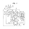
- Figure 1 The arrangement of Figure 1 includes a fuel cell 10, a turbine 20, an air compressor 21, a reformer 30, a shift converter 40, a heat accumulator 50, and condensers 60 and 61.
- the fuel cell 10 includes a cathode chamber 11, a cathode 12, an electrolyte 13, an anode 14, an anode chamber 15 and a cooling portion 16.
- a plurality of fuel cells are electrically connected, but they are depicted as a single cell in Figure 1.
- a proper load 17 is connected across the cathode 12 and the anode 14.
- the fuel cell shown in Figure 1 is of the oxygen-hydrogen type, which obtains oxygen from the air and obtains hydrogen by reforming a fuel containing carbon, with steam.
- the reformer 30 is constructed of a burner 31 and a reaction chamber 32, and if necessary, the reaction chamber 32-is filled with a catalyst.
- the shift converter 40 is filled with a catalyst, and is equipped with a heat exchanger for taking out reaction heat.
- the heat accumulator 50 is equipped with a plurality of heat exchangers, and is filled with a heat storing medium.
- the fuel such as naphtha and methane, and steam for reformation are supplied via lines . 82 and 104, and are fed to the reaction chamber 32 of the reformer 30.
- the fuel is reformed into hydrogen-rich gas in line 83.
- carbon monoxide produced in the reformer reacts with the steam, to be converted into hydrogen and carbonic acid gas.
- the hydrogen is supplied through line 84 into the anode chamber 15 of the fuel cell 10.
- the air is'compressed up to a predetermined pressure by the compressor 21 and is pressed through line 71 into the cathode chamber 11 of the fuel cell 10.
- voltage is generated across the cathode 12 and the anode 14 by the electrochemical reaction in the fuel cell, and electric power is derived by the load 17.
- the load is connected, the hydrogen of the anode chamber is consumed, and water is produced in the cathode chamber.
- the fuel cell is supplied with the fuel and the air more than are consumed therein, so as to emit gases from the cell, and the produced water is taken out of the cell.
- Gases emitted via lines 72 and 85 are supplied to the condensers 60 and 61, in which the water contents are condensed.
- the gases enter the burner 31 of the reformer 30 through lines 86 and 73, and are burnt.
- Part of the heat of the combustion gas is afforded to the reaction chamber 32, and is utilized for the reformation reaction described above.
- part of the combustion gas is supplied via lines 90 and 91 to the gas turbine 20 so as to reclaim waste energy.
- the gas turbine 20 drives the air compressor 21.
- the other part of the combustion gas ' is supplied via lines 90 and 93 to the heat exchanger of the heat accumulator 50 so as to store the waste energy in the heat accumulator 50.
- Reaction heat in the shift converter 40 is taken out via line 111 by a heat medium kept circulating by a pump 52,and is stored in the heat accumulator-50.
- the water components 100 and 101 condensed by the condensers are supplied via lines 100, 101 and 102 and by a pump 53 to the heat exchanger of the heat accumulator 50 and become the steam here.
- the steam is supplied via line 104 to the reformer reaction chamber 32.
- the heat stored in the heat accumulator 50 is afforded to the fuel cell by the heat.medium line 110 so as to raise the temperature of the cell. Also the temperature of the shift converter 40 is raised by the heat medium in line 111.
- the temperature of the heat accumulator 50 is determined by the thermal balance of the fuel cell 10, shift converter 40, combustion gas in line 93 and condensed water in-line 103.
- the temperature of the heat accumulator is therefore controlled by increasing or decreasing the flow rate of the combustion gas in line 93. In a case where the load has fluctuated, for example, where it has lowered,
- the heat accumulator 50 is preheated by ' e combustion gas in line 93,and the temperatures of the fuel cell 10 and the shift converter 40 are raised by the heat media in lines 110 and 111.Since this operation can be carried out prior to the connection of the load to the cell, the temperatures of the cell and the shift converter are sufficiently raised at the point of time of a load demand, so that power can be immediately generated.
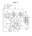
- Figure 2 shows another embodiment of the present invention.
- the arrangement of Figure 2 has further improved the system of Figure 1.
- the condensers 60 and 61 are additionally provided with heat exchangers 62 and 63 for outlet and inlet gases.
- a heat exchanger 54 which recovers the heat of the exhaust gas pf the gas turbine 20 supplied via line 92 as well as the outlet exhaust gas of the heat accumulator 50 supplied via line 94 is additionally disposed.
- the outlet gases of the condensers 60 and 61 are heated through heat exchanges with the emission gases (lines 72 and 85) of the fuel cell to high temperatures, and then supplied to the burner 31 of the reformer 30.
- the waste heats of the exhaust gas (line 92) of the gas turbine 20 and the outlet exhaust gas (line 94) of the heat accumulator 50 preheat the condensed water in line 102, and, if necessary, the preheating temperature is controlled by varying the flow rates of both the gases.
- the temperature of fuel cells can be held constant irrespective of the load level of the cells. Therefore, not only required power can be immediately generated upon a load demand, but also the performance of the cells can be held constant and the lifetime thereof can be prolonged owing to reduced thermal shocks. Further, since waste energy can be effectively recovered, the power generation efficiency is improved.
Landscapes
- Life Sciences & Earth Sciences (AREA)
- Engineering & Computer Science (AREA)
- Manufacturing & Machinery (AREA)
- Sustainable Development (AREA)
- Sustainable Energy (AREA)
- Chemical & Material Sciences (AREA)
- Chemical Kinetics & Catalysis (AREA)
- Electrochemistry (AREA)
- General Chemical & Material Sciences (AREA)
- Fuel Cell (AREA)
Applications Claiming Priority (2)
| Application Number | Priority Date | Filing Date | Title |
|---|---|---|---|
| JP56120786A JPS5823169A (ja) | 1981-08-03 | 1981-08-03 | 燃料電池発電装置およびその運転方法 |
| JP120786/81 | 1981-08-03 |
Publications (3)
| Publication Number | Publication Date |
|---|---|
| EP0071967A2 true EP0071967A2 (de) | 1983-02-16 |
| EP0071967A3 EP0071967A3 (en) | 1983-07-20 |
| EP0071967B1 EP0071967B1 (de) | 1986-07-30 |
Family
ID=14794958
Family Applications (1)
| Application Number | Title | Priority Date | Filing Date |
|---|---|---|---|
| EP82107013A Expired EP0071967B1 (de) | 1981-08-03 | 1982-08-03 | Brennstoffzellenenergiegewinnungssystem und Verfahren zum Betrieb desselben |
Country Status (4)
| Country | Link |
|---|---|
| US (1) | US4464444A (de) |
| EP (1) | EP0071967B1 (de) |
| JP (1) | JPS5823169A (de) |
| DE (1) | DE3272300D1 (de) |
Cited By (6)
| Publication number | Priority date | Publication date | Assignee | Title |
|---|---|---|---|---|
| EP0170277A3 (en) * | 1984-07-31 | 1987-08-05 | Hitachi, Ltd. | Fuel cell power plant |
| WO1989010010A1 (fr) * | 1988-04-16 | 1989-10-19 | Mtu Motoren- Und Turbinen-Union Friedrichshafen Gm | Installation de production d'energie electrique a partir de combustibles avec des cellules electrochimiques de combustible |
| EP0345908A1 (de) * | 1988-06-10 | 1989-12-13 | Kti Group B.V. | Verfahren zur Umwandlung von Brennstoff in Elektrizität |
| EP0361612A3 (en) * | 1988-09-26 | 1990-07-25 | Kti Group B.V. | Method for generating electricity |
| AT406718B (de) * | 1998-10-08 | 2000-08-25 | Vaillant Gmbh | Blockheizkraftwerk |
| EP3396759A4 (de) * | 2015-12-25 | 2019-01-09 | Panasonic Intellectual Property Management Co., Ltd. | Brennstoffzellensystem |
Families Citing this family (30)
| Publication number | Priority date | Publication date | Assignee | Title |
|---|---|---|---|---|
| JPS6041771A (ja) * | 1983-08-17 | 1985-03-05 | Hitachi Ltd | 燃料電池装置 |
| US4539267A (en) * | 1984-12-06 | 1985-09-03 | United Technologies Corporation | Process for generating steam in a fuel cell powerplant |
| JP2511866B2 (ja) * | 1986-02-07 | 1996-07-03 | 株式会社日立製作所 | 燃料電池発電システム及びその起動方法 |
| JPS62279033A (ja) * | 1986-05-27 | 1987-12-03 | Nichirin Rubber Kogyo Kk | 配管用パイプのビ−ド形成方法 |
| US4743517A (en) * | 1987-08-27 | 1988-05-10 | International Fuel Cells Corporation | Fuel cell power plant with increased reactant pressures |
| US7066973B1 (en) | 1996-08-26 | 2006-06-27 | Nuvera Fuel Cells | Integrated reformer and shift reactor |
| JP2000185901A (ja) * | 1998-12-21 | 2000-07-04 | Aisin Seiki Co Ltd | 改質装置および燃料電池システム |
| DE19908905C2 (de) * | 1999-03-02 | 2003-03-20 | Daimler Chrysler Ag | Brennstoffzellensystem mit zugeordneter Wasserstofferzeugungsanlage |
| US6986797B1 (en) | 1999-05-03 | 2006-01-17 | Nuvera Fuel Cells Inc. | Auxiliary reactor for a hydrocarbon reforming system |
| US6641625B1 (en) | 1999-05-03 | 2003-11-04 | Nuvera Fuel Cells, Inc. | Integrated hydrocarbon reforming system and controls |
| DE19922923C2 (de) * | 1999-05-19 | 2002-02-21 | Siemens Ag | Flüssigkeitsgekühlte Brennstoffzellenbatterie und Verfahren zum Betreiben einer flüssigkeitsgekühlten Brennstoffzellenbatterie |
| JP4513168B2 (ja) * | 2000-05-15 | 2010-07-28 | トヨタ自動車株式会社 | 燃料電池装置と給湯装置のコンバインシステム |
| JP4502468B2 (ja) * | 2000-07-07 | 2010-07-14 | 大阪瓦斯株式会社 | 燃料電池発電装置 |
| JP2002042840A (ja) * | 2000-07-24 | 2002-02-08 | Toyota Motor Corp | 燃料電池型コージェネレーションシステム |
| DE10054842A1 (de) * | 2000-11-04 | 2002-08-29 | Xcellsis Gmbh | Verfahren zur elektrischen Inbetriebnahme einer Brennstoffzelle |
| JP2002289227A (ja) * | 2001-03-23 | 2002-10-04 | Aisin Seiki Co Ltd | 燃料電池コージェネレーションシステム |
| FR2823704B1 (fr) * | 2001-04-20 | 2003-07-04 | Renault | Dispositif de gestion thermique d'un vehicule automobile |
| US7507384B2 (en) | 2002-06-13 | 2009-03-24 | Nuvera Fuel Cells, Inc. | Preferential oxidation reactor temperature regulation |
| US6743410B2 (en) * | 2002-08-02 | 2004-06-01 | General Motors Corporation | Primary reactor liquid water and air injection for improved management of a fuel processor |
| JP4955915B2 (ja) * | 2004-06-11 | 2012-06-20 | 株式会社豊田中央研究所 | 燃料電池システム |
| CN101091273A (zh) * | 2004-12-29 | 2007-12-19 | Utc电力公司 | 具有用于实现延长寿命的工作温度的燃料电池组件 |
| RU2448394C2 (ru) * | 2004-12-29 | 2012-04-20 | ЮТиСи Пауэ Копэрейшн | Способ эксплуатации батареи топливных элементов (варианты) и батарея топливных элементов |
| JP2006327864A (ja) * | 2005-05-26 | 2006-12-07 | Nitto Denko Corp | 水素発生装置及び水素発生方法 |
| FR2886766B1 (fr) * | 2005-06-07 | 2010-10-22 | Renault Sas | Systeme de pile a combustible perfectionne et procede de production d'eau associe |
| JP4486618B2 (ja) | 2006-06-06 | 2010-06-23 | 株式会社リコー | 充電回路、充電回路の動作制御方法及び電源装置 |
| US9548504B2 (en) * | 2012-01-24 | 2017-01-17 | University Of Connecticut | Utilizing phase change material, heat pipes, and fuel cells for aircraft applications |
| JP6099408B2 (ja) * | 2013-01-18 | 2017-03-22 | 三菱日立パワーシステムズ株式会社 | 発電システム、及び発電システムの運転方法 |
| GB2621074B (en) | 2021-05-20 | 2025-02-19 | Nabors Energy Transition Solutions Llc | Systems and methods for a hydrogen zero emissions vehicle |
| JP7236200B1 (ja) * | 2022-03-31 | 2023-03-09 | 三菱重工業株式会社 | 水素生成システムおよび水素生成方法 |
| DE102022120291A1 (de) * | 2022-08-11 | 2024-02-22 | Purem GmbH | Brennstoffzellenabgasanlage |
Family Cites Families (4)
| Publication number | Priority date | Publication date | Assignee | Title |
|---|---|---|---|---|
| US3336162A (en) * | 1963-07-03 | 1967-08-15 | Martin Marietta Corp | Fuel cell and electrical generator system |
| DE2414758B2 (de) * | 1974-03-27 | 1976-04-15 | Varta Batterie Ag, 3000 Hannover | Elektrolyt-kuehlvorrichtung fuer aus mehreren zellen bestehende akkumulatorenbatterien |
| DE2604981C2 (de) * | 1975-02-12 | 1985-01-03 | United Technologies Corp., Hartford, Conn. | Unter Druck betriebene Brennstoffzellenstromversorgungsanlagen und Verfahren zu ihrem Betrieb |
| US4041210A (en) * | 1976-08-30 | 1977-08-09 | United Technologies Corporation | Pressurized high temperature fuel cell power plant with bottoming cycle |
-
1981
- 1981-08-03 JP JP56120786A patent/JPS5823169A/ja active Granted
-
1982
- 1982-07-29 US US06/403,011 patent/US4464444A/en not_active Expired - Fee Related
- 1982-08-03 EP EP82107013A patent/EP0071967B1/de not_active Expired
- 1982-08-03 DE DE8282107013T patent/DE3272300D1/de not_active Expired
Cited By (7)
| Publication number | Priority date | Publication date | Assignee | Title |
|---|---|---|---|---|
| EP0170277A3 (en) * | 1984-07-31 | 1987-08-05 | Hitachi, Ltd. | Fuel cell power plant |
| WO1989010010A1 (fr) * | 1988-04-16 | 1989-10-19 | Mtu Motoren- Und Turbinen-Union Friedrichshafen Gm | Installation de production d'energie electrique a partir de combustibles avec des cellules electrochimiques de combustible |
| US5156926A (en) * | 1988-04-16 | 1992-10-20 | Mtu Friedrichshafen Gmbh | System for generating electric energy from fuels having electrochemically acting fuel cells |
| EP0345908A1 (de) * | 1988-06-10 | 1989-12-13 | Kti Group B.V. | Verfahren zur Umwandlung von Brennstoff in Elektrizität |
| EP0361612A3 (en) * | 1988-09-26 | 1990-07-25 | Kti Group B.V. | Method for generating electricity |
| AT406718B (de) * | 1998-10-08 | 2000-08-25 | Vaillant Gmbh | Blockheizkraftwerk |
| EP3396759A4 (de) * | 2015-12-25 | 2019-01-09 | Panasonic Intellectual Property Management Co., Ltd. | Brennstoffzellensystem |
Also Published As
| Publication number | Publication date |
|---|---|
| DE3272300D1 (en) | 1986-09-04 |
| JPS6351352B2 (de) | 1988-10-13 |
| JPS5823169A (ja) | 1983-02-10 |
| EP0071967B1 (de) | 1986-07-30 |
| US4464444A (en) | 1984-08-07 |
| EP0071967A3 (en) | 1983-07-20 |
Similar Documents
| Publication | Publication Date | Title |
|---|---|---|
| US4464444A (en) | Fuel cell power generation system and method of operating the same | |
| US4678723A (en) | High pressure low heat rate phosphoric acid fuel cell stack | |
| US6195999B1 (en) | Electrochemical engine | |
| US5221586A (en) | Power generation system using fuel cells | |
| US6277508B1 (en) | Fuel cell power supply with exhaust recycling for improved water management | |
| US4828940A (en) | Fuel cell power plant with increased reactant pressures | |
| US5780179A (en) | Fuel cell system for use on mobile bodies | |
| EP2756538B1 (de) | Brennstoffzellensystem | |
| US5187024A (en) | Fuel cell generating system | |
| US4686157A (en) | Fuel cell power system | |
| US6758981B2 (en) | Method and apparatus for by-product removal in a hydrogen generation system | |
| CN108604695A (zh) | 利用具有发动机的rep的能量储存 | |
| EP1571727B1 (de) | Vorrichtung und Verfahren zum Betrieb einer Hochtemperatur-Brennstoffzellenanlage mit aufbereitetem Anodenabgas | |
| JP3105668B2 (ja) | 電力貯蔵装置 | |
| US4352863A (en) | Apparatus and method for producing high pressure steam in a fuel cell system | |
| JPH0845526A (ja) | 多段反応型燃料電池 | |
| US6124050A (en) | Process for operating a high temperature fuel cell installation, and high temperature fuel cell installation | |
| JP2000215901A (ja) | 固体高分子型燃料電池システム | |
| EP1791208A2 (de) | Brennstoffzellensystem | |
| JPS5834575A (ja) | 燃料電池発電システム | |
| JPH08339815A (ja) | 燃料電池発電装置 | |
| JPH117972A (ja) | 燃料電池発電装置 | |
| JP2019106288A (ja) | 水素電力貯蔵システムおよび水素電力貯蔵方法 | |
| JPH04345766A (ja) | 燃料電池発電プラントの熱併給発電システム | |
| JP3080757B2 (ja) | アルカリ金属熱電変換複合発電装置 |
Legal Events
| Date | Code | Title | Description |
|---|---|---|---|
| PUAI | Public reference made under article 153(3) epc to a published international application that has entered the european phase |
Free format text: ORIGINAL CODE: 0009012 |
|
| AK | Designated contracting states |
Designated state(s): DE GB NL |
|
| PUAL | Search report despatched |
Free format text: ORIGINAL CODE: 0009013 |
|
| AK | Designated contracting states |
Designated state(s): DE GB NL |
|
| 17P | Request for examination filed |
Effective date: 19830728 |
|
| GRAA | (expected) grant |
Free format text: ORIGINAL CODE: 0009210 |
|
| AK | Designated contracting states |
Kind code of ref document: B1 Designated state(s): DE GB NL |
|
| REF | Corresponds to: |
Ref document number: 3272300 Country of ref document: DE Date of ref document: 19860904 |
|
| PLBE | No opposition filed within time limit |
Free format text: ORIGINAL CODE: 0009261 |
|
| STAA | Information on the status of an ep patent application or granted ep patent |
Free format text: STATUS: NO OPPOSITION FILED WITHIN TIME LIMIT |
|
| 26N | No opposition filed | ||
| PGFP | Annual fee paid to national office [announced via postgrant information from national office to epo] |
Ref country code: NL Payment date: 19960703 Year of fee payment: 15 |
|
| PGFP | Annual fee paid to national office [announced via postgrant information from national office to epo] |
Ref country code: DE Payment date: 19961028 Year of fee payment: 15 |
|
| PG25 | Lapsed in a contracting state [announced via postgrant information from national office to epo] |
Ref country code: NL Free format text: LAPSE BECAUSE OF NON-PAYMENT OF DUE FEES Effective date: 19980301 |
|
| PG25 | Lapsed in a contracting state [announced via postgrant information from national office to epo] |
Ref country code: DE Free format text: LAPSE BECAUSE OF NON-PAYMENT OF DUE FEES Effective date: 19980501 |
|
| NLV4 | Nl: lapsed or anulled due to non-payment of the annual fee |
Effective date: 19980301 |
|
| PGFP | Annual fee paid to national office [announced via postgrant information from national office to epo] |
Ref country code: GB Payment date: 19990723 Year of fee payment: 18 |
|
| PG25 | Lapsed in a contracting state [announced via postgrant information from national office to epo] |
Ref country code: GB Free format text: LAPSE BECAUSE OF NON-PAYMENT OF DUE FEES Effective date: 20000803 |
|
| GBPC | Gb: european patent ceased through non-payment of renewal fee |
Effective date: 20000803 |