EP0071955B1 - System to control the drive of conveyors operating in combination - Google Patents
System to control the drive of conveyors operating in combination Download PDFInfo
- Publication number
- EP0071955B1 EP0071955B1 EP82106993A EP82106993A EP0071955B1 EP 0071955 B1 EP0071955 B1 EP 0071955B1 EP 82106993 A EP82106993 A EP 82106993A EP 82106993 A EP82106993 A EP 82106993A EP 0071955 B1 EP0071955 B1 EP 0071955B1
- Authority
- EP
- European Patent Office
- Prior art keywords
- distribution
- conveyors
- conveyor
- conveyor tracks
- bottles
- Prior art date
- Legal status (The legal status is an assumption and is not a legal conclusion. Google has not performed a legal analysis and makes no representation as to the accuracy of the status listed.)
- Expired
Links
Images
Classifications
-
- B—PERFORMING OPERATIONS; TRANSPORTING
- B65—CONVEYING; PACKING; STORING; HANDLING THIN OR FILAMENTARY MATERIAL
- B65G—TRANSPORT OR STORAGE DEVICES, e.g. CONVEYORS FOR LOADING OR TIPPING, SHOP CONVEYOR SYSTEMS OR PNEUMATIC TUBE CONVEYORS
- B65G43/00—Control devices, e.g. for safety, warning or fault-correcting
- B65G43/10—Sequence control of conveyors operating in combination
Definitions
- the invention relates to a method for the continuous transport speed control of carriers according to the preamble of claim 1 (known from DE-A-2 505 622.
- DE-A-2 505 622 describes a conveyor track with two stations for treating objects, in which a counting device is provided at the point where the objects come from the conveyor onto the buffer line. A further counting device is provided at the point where the objects are transferred from the line to the feed conveyor.
- the two counting organs are connected via a line to a registration device which registers the difference between the numerical values determined by the two counting organs. The registered difference is used to regulate the control speed of the buffer section conveyor in which the registration device is connected to the motor via a line.
- This known method is based essentially on the difference in the number of objects on a conveyor section. The disadvantages contained in this process can be described as follows:
- the invention has now, while avoiding the disadvantages shown, the task of constantly having such a number of vessels, bottles, cans and the like available on the respective transport sections without back pressure, as is necessary for the complete loading of the subsequent treatment machine, taking into account the throughput the corresponding machines in the area of such a route should have a catch-up transport speed and, if there is sufficient or excess bottle material, this speed should be influenced.
- This method according to the invention ensures that the material to be conveyed is largely free of dynamic pressure on completely filled transport sections.
- the minimum dynamic pressure required to maintain the necessary packing density is set by regulating the transport speed.
- This minimum or optimized pressure is essentially constantly available, so that otherwise usually unavoidable excessive pressure loads on the material being conveyed are generally eliminated.
- this partial back pressure is predominantly generated in the front part facing the treatment machine or in the section transitions.
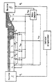
- the embodiment shows a treatment machine A with a further treatment machine B connected downstream in the transport flow.
- the actual intermediate conveyor S which consists of several individual sections S1 to S5 .
- the speed of each of these transport sections is continuously adjustable.
- Sensors 1 to 4 are assigned to these sections.
- the pulses from these sensors 1 to 4 are available both to a central processing point C, for example a computer, and to a decentralized processing point D assigned to a machine B and / or a section S5.
- the speed setting for each individual transport section of the decentralized processing point D can be transmitted from a central processing point C via switching elements E 1 to E 3.
- a microprocessor for example, can be provided as the decentralized processing point D, which controls a vessel separation system without back pressure upstream of the treatment machine.
- the system is shown in a medium operating state.
- Reusable bottles are treated, for example.
- the bottles leave the treatment machine A in an undamaged, loose formation and are transported on the sections S1 to S3 at the maximum achievable speed.
- the speed specification for sections S1 and S2 is made by the central processing point C.
- the bottles connect to the bulk of bottles located in sections S4 and S5.
- the central processing point C sets on section S3 a speed which is dependent on the length of the group on S3. the feed rate is reduced as the pulse length increases. In this way, only the connection pressure required to connect the bottles to the end of the batch builds up on S3.
- the decentralized processing point D assigns the section S4 a conveying speed adapted to the throughput of the treatment machine B, which guarantees pressure-free transport of the conveyed material or the bottles in this area.
- Section S5 is influenced in accordance with S4.
- the information for determining the individual section speeds and switching from the central computer to the decentralized processing point D is obtained from the central computer C on the basis of a bottle tracking influenced by the throughput of the assigned machines A, B.
- the process computer 4 determines and stores the position of each bottle located on the conveyor belts or sections S1 to S5 as well as the position of the respective end of the group and the number of bottles in the group.
- the process computer provides this information for control purposes.
- the bottle tracking is influenced, corrected and, if necessary, adaptively changed and optimized by means of the sensors 1 to 4 arranged on the individual sections S1 to S4.
Description
Die Erfindung bezieht sich auf ein Verfahren zur kontinuierlichen Transportgeschwindigkeitsregelung von Transporteuren gemäß dem Oberbegriff von Anspruch 1 (bekannt von DE-A-2 505 622.The invention relates to a method for the continuous transport speed control of carriers according to the preamble of claim 1 (known from DE-A-2 505 622.
Beispielsweise in der Getränkeindustrie befinden sich zwischen den einzelnen Behandlungsmaschinen Transporteure, deren jeweiliger Befüllungsgrad mittels Staudruckschalter ermittelt wird. Zur Verminderung des auf diesen Transporteuren anstehenden Staudrucks werden die jeweils gefüllten Förderstrecken durch Betätigung dieser Schalter teilweise stillgesetzt und nach Auflösen des Staus wieder angetrieben. In derartigen Fällen wird ![]()
![]()
![]()
![]()
Diese vorgeschilderten Nachteile können auch bei einer stufenweisen Geschwindigkeitssteuerung, beispielsweise bei Einsatz von polumschaltbaren Motoren oder dgl., nicht beseitigt werden.These disadvantages described above cannot be eliminated even with step-by-step speed control, for example when using pole-changing motors or the like.
Entsprechend dem Oberbegriff von Anspruch 1 beschreibt die DE-A-2 505 622 eine Förderbahn mit zwei Stationen zum Behandeln von Gegenständen, bei welcher an derjenigen Stelle, wo die Gegenstände vom Förderer auf die Pufferstrecke gelangen, ein Zählorgan vorgesehen ist. An der Stelle, wo die Gegenstände aus der Schlange auf den Beschickungsförderer überführt werden, ist ein weiteres Zählorgan vorgesehen. Die beiden Zählorgane sind über eine Leitung an eine Registriervorrichtung angeschlossen, welche die Differenz zwischen den von den beiden Zählorganen ermittelten Zahlenwertenregistriert. Die registrierte Differenz dient zur Regelung der Steuergeschwindigkeit des Pufferstreckenförderers, in dem die Registriervorrichtung über eine Leitung mit dem Motor verbunden ist. Dieses bekannte Verfahren beruht im wesentlichen auf der Differenzanzahlbestimmung von Gegenständen auf einem Förderabschnitt. Die in diesem Verfahren enthaltenen Nachteile sind folgendermaßen zu beschreiben :According to the preamble of claim 1, DE-A-2 505 622 describes a conveyor track with two stations for treating objects, in which a counting device is provided at the point where the objects come from the conveyor onto the buffer line. A further counting device is provided at the point where the objects are transferred from the line to the feed conveyor. The two counting organs are connected via a line to a registration device which registers the difference between the numerical values determined by the two counting organs. The registered difference is used to regulate the control speed of the buffer section conveyor in which the registration device is connected to the motor via a line. This known method is based essentially on the difference in the number of objects on a conveyor section. The disadvantages contained in this process can be described as follows:
Eine exakte Geschwindigkeitseinstellung auf Transportstrecken ist nicht möglich, da die Grenzlinie der frei transportierten Gegenstände zu den im Stau befindlichen Gegenständen nicht exakt lokalisiert werden kann. Die einfache Differenzmessung zeigt zwar die z. Zt. aktuelle Anzahl von Gegenständen auf einem solchen Transportband, gibt aber keine Information über die eigentliche Dichte-Verteilung der transportierten Gegenstände an.An exact speed setting on transport routes is not possible because the boundary line of the freely transported objects to the objects in the traffic jam cannot be exactly located. The simple difference measurement shows the z. Current number of objects on such a conveyor belt, but does not provide any information about the actual density distribution of the transported objects.
Dies gilt auch für den aus der US-PS-3 200 932 bekannten Stand der Technik.This also applies to the prior art known from US Pat. No. 3,200,932.
Die Erfindung hat sich nun unter Vermeidung der aufgezeigten Nachteile die Aufgabe gestellt, ständig eine solche Anzahl von Gefäßen, Flaschen, Dosen und dgl. auf den jeweiligen Transportabschnitten staudrucklos bereitzuhalten, wie sie zur lückenlosen Beschickung der nachfolgenden Behandlungsmaschine notwendig ist, wobei unter Berücksichtigung der Durchsatzleistung der miteinander korrespondierenden Maschinen im Bereich einer solchen Strecke eine Aufholtransportgeschwindigkeit und bei ausreichendem bzw. überschüssigem Flaschenmaterial eine Beeinflussung dieser Geschwindigkeit gegeben sein soll. Diese Aufgabe wird gemäß der Erfindung bei einem Verfahren der eingangs genannten Art dadurch gelöst, daß der Befüllungsgrad der einzelnen Förderstrecken und die Trennlinie gestauter Flaschen zu frei transportierten Flaschen aufgrund der Durchsatzleistung vor und hinter diesen Zwischenförderern durch eine Flaschenpositionsverfolgung ermittelt wird und daß die auf diese Weise erhaltene Flaschenzahl und deren flächenmäßige Verteilung auf diesen Zwischenförderern in ein Leitsignal zur kontinuierlichen Regelung der Transportgeschwindigkeit der Förderstrecken und/oder Verteil- bzw. Zusammenführstationen umgesetzt wird. Weitere Merkmale der Erfindung ergeben sich aus den weiteren Ansprüchen.The invention has now, while avoiding the disadvantages shown, the task of constantly having such a number of vessels, bottles, cans and the like available on the respective transport sections without back pressure, as is necessary for the complete loading of the subsequent treatment machine, taking into account the throughput the corresponding machines in the area of such a route should have a catch-up transport speed and, if there is sufficient or excess bottle material, this speed should be influenced. This object is achieved according to the invention in a method of the type mentioned at the outset in that the degree of filling of the individual conveyor lines and the dividing line of jammed bottles to freely transported bottles is determined on the basis of the throughput capacity in front of and behind these intermediate conveyors by means of a bottle position tracking and in that way number of bottles obtained and their area distribution on these intermediate conveyors is converted into a control signal for the continuous regulation of the transport speed of the conveying lines and / or distribution or merging stations. Further features of the invention result from the further claims.
Mit diesem erfindungsgemäßen Verfahren wird ein weitgehendst staudruckfreier Transport des Fördergutes auf vollständig gefüllten Transportabschnitten sichergestellt. Auf teilweise gefüllten Transportabschnitten wird durch Regelung der Transportgeschwindigkeit der minimale Staudruck, der zur Aufrechterhaltung der jeweils notwendigen Packungsdichte erforderlich ist, eingestellt. Dieser minimale bzw. optimierte Druck steht dabei im wesentlichen konstant zur Verfügung, so daß sonst übliche partiell unvermeidbare übermäßige Druckbeanspruchungen des jeweiligen Fördergutes grundsätzlich ausgeschaltet werden. Dieser partielle Staudruck entsteht bei Förderern gemäß dem Stand der Technik vorwiegend im vorderen, der Behandlungsmaschine zugewandten Teil bzw. in den Abschnittsübergängen.This method according to the invention ensures that the material to be conveyed is largely free of dynamic pressure on completely filled transport sections. On partially filled transport sections, the minimum dynamic pressure required to maintain the necessary packing density is set by regulating the transport speed. This minimum or optimized pressure is essentially constantly available, so that otherwise usually unavoidable excessive pressure loads on the material being conveyed are generally eliminated. In the case of conveyors according to the prior art, this partial back pressure is predominantly generated in the front part facing the treatment machine or in the section transitions.
Aufgrund der durch das erfindungsgemäße Verfahren gegebenen Informationen im Hinblick auf die aktuelle Befüllung der jeweiligen Abschnitte können auch gering befüllte Abschnitte mit hohen Geschwindigkeiten gefahren werden, die bei sonst üblichen Transportanlagen aufgrund der Lärmemissionen und der starken Beanspruchung des Fördergutes nicht verwirklicht werden können. Ein weiterer wesentlicher Vorteil der Erfindung besteht darin, daß aufgrund der höheren Arbeits- bzw. Abschnittsgeschwindigkeiten größere effektive Pufferkapazitäten erreicht werden, die bei den bekannten Anlagen nur durch entsprechende Vergrößerung der eigentlichen Transportfläche gegeben sind bzw. zur Verfügung gestellt werden können.On the basis of the information given by the method according to the invention with regard to the current filling of the respective sections, even slightly filled sections can be driven at high speeds, which cannot be achieved in otherwise conventional transport systems due to the noise emissions and the heavy loads on the conveyed goods. Another significant advantage of the invention is that, due to the higher working or section speeds, larger effective buffer capacities are achieved are that are given or can be made available in the known systems only by a corresponding increase in the actual transport area.
Im nachfolgenden wird die Erfindung anhand eines in der Zeichnung dargestellten Ausführungsbeispiels erläutert : Das Ausführungsbeispiel zeigt eine Behandlungsmachine A mit einer im Transportfluß nachgeschalteten weiteren Behandlungsmaschine B. Zwischen beiden Maschinen A, B befindet sich der eigentliche Zwischenförderer S, der aus mehreren Einzelabschnitten S1 bis S5 besteht. Jeder dieser Transportabschnitte ist in seiner Geschwindigkeit kontinuierlich einstellbar. Diesen Abschnitten sind Sensoren 1 bis 4 zugeordnet. Die Impulse dieser Sensoren 1 bis 4 stehen sowohl einer zentralen Verarbeitungsstelle C, beispielsweise einem Rechner, als auch einer dezentralen, einer Maschine B und/oder einem Abschnitt S5 zugeordneten Verarbeitungsstelle D zur Verfügung.The invention is explained below with reference to an embodiment shown in the drawing: The embodiment shows a treatment machine A with a further treatment machine B connected downstream in the transport flow. Between the two machines A, B there is the actual intermediate conveyor S, which consists of several individual sections S1 to S5 . The speed of each of these transport sections is continuously adjustable. Sensors 1 to 4 are assigned to these sections. The pulses from these sensors 1 to 4 are available both to a central processing point C, for example a computer, and to a decentralized processing point D assigned to a machine B and / or a section S5.
Über Umschaltorgane E 1 bis E 3 kann von einer zentralen Verarbeitungsstelle C die Geschwindigkeitsvorgabe für jeden einzelnen Transportabschnitt der dezentralen Verarbeitungsstelle D übertragen werden. Als dezentrale Verarbeitungsstelle D kann beispielsweise ein Mikroprozessor vorgesehen sein, der eine staudrucklose Gefäßvereinzelungsanlage vor der Behandlungsmaschine ansteuert.The speed setting for each individual transport section of the decentralized processing point D can be transmitted from a central processing point C via switching elements E 1 to E 3. A microprocessor, for example, can be provided as the decentralized processing point D, which controls a vessel separation system without back pressure upstream of the treatment machine.
Im Ausführungsbeispiel ist die Anlage in einem mittleren Betriebszustand dargestellt. Es werden beispielsweise Mehrwegflaschen behandelt. Die Flaschen verlassen die Behandlungsmaschine A in ungestauter lockerer Formation und werden auf den Abschnitten S1 bis S3 mit maximal erreichbarer Geschwindigkeit weitertransportiert. Die Geschwindigkeitsvorgabe für die Abschnite S1 und S2 erfolgt von der zentralen Verarbeitungsstelle C. Im Bereich des Abschnittes S3 schließen sich die Flaschen dem sich auf den Abschnitten S4 und S5 befindlichen Flaschenpulk an. Die zentrale Verarbeitungsstelle C stellt auf dem Abschnitt S3 eine von der Länge des Pulks auf S3 abhängige Geschwindigkeit ein. nabei wird mit zunehmender Pulklänge die Zuführgeschwindigkeit vermindert. Auf diese Weise baut sich auf S3 nur der zum Anschließen der Flaschen an das Ende des Pulks notwendige Anschlußdruck auf.In the exemplary embodiment, the system is shown in a medium operating state. Reusable bottles are treated, for example. The bottles leave the treatment machine A in an undamaged, loose formation and are transported on the sections S1 to S3 at the maximum achievable speed. The speed specification for sections S1 and S2 is made by the central processing point C. In the area of section S3, the bottles connect to the bulk of bottles located in sections S4 and S5. The central processing point C sets on section S3 a speed which is dependent on the length of the group on S3. the feed rate is reduced as the pulse length increases. In this way, only the connection pressure required to connect the bottles to the end of the batch builds up on S3.
Demgegenüber weist die dezentrale Verarbeitungsstelle D dem Abschnitt S4 eine der Durchsatzleistung der Behandlungsmaschine B angepaßte Fördergeschwindigkeit zu, die in diesem Bereich einen drucklosen Transport des Fördergutes bzw. der Flaschen garantiert. Der Abschnitt S5 wird entsprechend S4 beeinflußt. Die Information zur Bestimmung der einzelnen Abschnittsgeschwindigkeiten sowie Umschaltung vom zentralen Rechner auf die dezentrale Verarbeitungsstelle D werden vom zentralen Rechner C aufgrund einer von den Durchsatzleistungen der zugeordneten Maschinen A, B beeinflußten Flaschenverfolgung gewonnen. Zu diesem Zwecke ermittelt und speichert der Prozeßrechner 4 die Position jeder auf den Transportbändern bzw. Abschnitten S1 bis S5 befindlichen Flaschen sowie die Position des jeweiligen Pulkendes und die im Pulk befindliche Flaschenzahl.In contrast, the decentralized processing point D assigns the section S4 a conveying speed adapted to the throughput of the treatment machine B, which guarantees pressure-free transport of the conveyed material or the bottles in this area. Section S5 is influenced in accordance with S4. The information for determining the individual section speeds and switching from the central computer to the decentralized processing point D is obtained from the central computer C on the basis of a bottle tracking influenced by the throughput of the assigned machines A, B. For this purpose, the process computer 4 determines and stores the position of each bottle located on the conveyor belts or sections S1 to S5 as well as the position of the respective end of the group and the number of bottles in the group.
Diese Information stellt der Prozeßrechner zur Regelung zur Verfügung. Die Flaschenverfolgung wird mittels der an den einzelnen Abschnitten S1 bis S4 angeordneten Sensoren 1 bis 4 beeinflußt, korrigiert und gegebenenfalls adaptiv verändert und optimiert.The process computer provides this information for control purposes. The bottle tracking is influenced, corrected and, if necessary, adaptively changed and optimized by means of the sensors 1 to 4 arranged on the individual sections S1 to S4.
Claims (7)
Applications Claiming Priority (2)
| Application Number | Priority Date | Filing Date | Title |
|---|---|---|---|
| DE3131352 | 1981-08-07 | ||
| DE19813131352 DE3131352A1 (en) | 1981-08-07 | 1981-08-07 | METHOD FOR CONTINUOUS TRANSPORT SPEED CONTROL OF TRANSPORTERS |
Publications (3)
| Publication Number | Publication Date |
|---|---|
| EP0071955A2 EP0071955A2 (en) | 1983-02-16 |
| EP0071955A3 EP0071955A3 (en) | 1983-04-27 |
| EP0071955B1 true EP0071955B1 (en) | 1986-09-10 |
Family
ID=6138850
Family Applications (1)
| Application Number | Title | Priority Date | Filing Date |
|---|---|---|---|
| EP82106993A Expired EP0071955B1 (en) | 1981-08-07 | 1982-08-03 | System to control the drive of conveyors operating in combination |
Country Status (3)
| Country | Link |
|---|---|
| EP (1) | EP0071955B1 (en) |
| JP (1) | JPS5874413A (en) |
| DE (2) | DE3131352A1 (en) |
Cited By (1)
| Publication number | Priority date | Publication date | Assignee | Title |
|---|---|---|---|---|
| US9254966B2 (en) | 2013-05-21 | 2016-02-09 | Krones Ag | Monitoring and control of a transport device for containers |
Families Citing this family (12)
| Publication number | Priority date | Publication date | Assignee | Title |
|---|---|---|---|---|
| DE3661253D1 (en) * | 1985-08-28 | 1988-12-29 | Sig Schweiz Industrieges | Method and device for conveying flat objects, especially biscuits |
| US4729105A (en) * | 1986-02-20 | 1988-03-01 | Adolph Coors Company | Continuous processing system with accumulator model for product flow control |
| DE3616023A1 (en) * | 1986-05-13 | 1987-11-19 | Seitz Enzinger Noll Masch | BUFFER TRANSPORTER FOR CONVEYOR ACTING AS BUFFER FROM VESSEL TREATMENT PLANTS FOR BOTTLES OR THE LIKE VESSELS |
| JPS6347223A (en) * | 1986-08-11 | 1988-02-29 | Shibuya Kogyo Co Ltd | Operation control unit for container collecting device |
| US4852717A (en) * | 1986-11-12 | 1989-08-01 | Fmc Corporation | Computer controlled light contact feeder |
| DE4002414A1 (en) * | 1990-01-27 | 1991-08-01 | Krause Johann A Maschf | METHOD AND DEVICE FOR TRANSPORTING OBJECTS ALONG A PRODUCTION ROAD |
| US5228558A (en) * | 1991-12-23 | 1993-07-20 | Interroll Holding A.G. | Control system for an accumulating conveyor |
| DE4232413C2 (en) * | 1992-09-28 | 1994-08-04 | Khs Masch & Anlagenbau Ag | Method and device for regulating the conveying capacity of mass transporters |
| DE19518275B4 (en) * | 1995-05-18 | 2004-02-19 | Saurer Gmbh & Co. Kg | Method for operating a transport system of an automatic winding machine and transport system |
| DE19955415A1 (en) * | 1999-11-18 | 2001-05-23 | Schlafhorst & Co W | Conveyor for feeding automatic winder includes device to prevent overfilling using comparison of signals from two sensors spaced along conveyor |
| DE10121833A1 (en) * | 2001-05-04 | 2002-11-14 | Krones Ag | Transport system for general cargo |
| DE10300642C5 (en) * | 2003-01-09 | 2018-02-22 | Krones Aktiengesellschaft | conveyor |
Family Cites Families (5)
| Publication number | Priority date | Publication date | Assignee | Title |
|---|---|---|---|---|
| US3200932A (en) * | 1964-04-14 | 1965-08-17 | Tamar Electronics Ind Inc | Motion control system |
| CH569643A5 (en) * | 1973-08-14 | 1975-11-28 | Sapal Plieuses Automatiques | |
| DK132654C (en) * | 1974-02-13 | 1976-06-14 | Forenede Bryggerier As | TRANSPORT PATH BETWEEN TWO PROCESSING STATIONS, AS BOTTLES |
| DE2830197A1 (en) * | 1978-07-10 | 1980-01-24 | Holstein & Kappert Maschf | Bottle separator for conveyor - has parallel bands of conveyor moved at different speeds at approach to guide walls |
| DE2830196A1 (en) * | 1978-07-10 | 1980-01-24 | Holstein & Kappert Maschf | Group transporter for bottles between conveyors - has wide blocks of equal length spaced to suit bottle dimensions |
-
1981
- 1981-08-07 DE DE19813131352 patent/DE3131352A1/en active Granted
-
1982
- 1982-08-03 EP EP82106993A patent/EP0071955B1/en not_active Expired
- 1982-08-03 DE DE8282106993T patent/DE3273195D1/en not_active Expired
- 1982-08-06 JP JP57136414A patent/JPS5874413A/en active Pending
Cited By (1)
| Publication number | Priority date | Publication date | Assignee | Title |
|---|---|---|---|---|
| US9254966B2 (en) | 2013-05-21 | 2016-02-09 | Krones Ag | Monitoring and control of a transport device for containers |
Also Published As
| Publication number | Publication date |
|---|---|
| DE3273195D1 (en) | 1986-10-16 |
| JPS5874413A (en) | 1983-05-04 |
| DE3131352C2 (en) | 1989-10-19 |
| EP0071955A3 (en) | 1983-04-27 |
| EP0071955A2 (en) | 1983-02-16 |
| DE3131352A1 (en) | 1983-02-17 |
Similar Documents
| Publication | Publication Date | Title |
|---|---|---|
| EP0399264B1 (en) | Method of and apparatus for changing the relative position of packs, especially of parallelepipedic cigarette packs of the flip-top type (hinge-lid pack) | |
| EP1771363B1 (en) | Method and device for dynamic gap optimisation | |
| EP0071955B1 (en) | System to control the drive of conveyors operating in combination | |
| DE102007040367B4 (en) | Material flow control to avoid collisions in a conveyor system | |
| EP0259733B1 (en) | Method and device for conveying piece goods and for changing their position | |
| EP2088099B1 (en) | Supply device for vertical transport of bulk goods | |
| DE202008009166U1 (en) | Transport device for feeding articles to a packaging machine | |
| DE202005013125U1 (en) | Single-lane container e.g. bottle, flow forming apparatus, has conveyors for container flow, intermediate area connected in conveyor, and separating area connecting intermediate area with conveyors | |
| EP2366640B1 (en) | Transport unit for a transport system for items and corresponding transport system | |
| DE2830197C2 (en) | ||
| EP0066119B1 (en) | Method of determining the filling degree of a buffer distance between container treating stations and for continuously controlling the throughput in such treating systems with a plurality of stations arranged in series or parallel to the running direction of the containers or bottles | |
| DE3025951A1 (en) | METHOD AND DEVICE FOR DIVIDING AND SEPARATING MULTIPLE-LEADING ENTRIES IN A SINGLE-LEADED TRACK | |
| DE10257466A1 (en) | Conveyors for goods, in particular containers for luggage and methods for controlling a conveyor for goods | |
| WO2004058604A1 (en) | Device for continuously delivering bags | |
| DE3505253C2 (en) | Bottle distribution station for converting a conveyed single-track bottle flow into a wide bottle flow to be removed | |
| EP0245806A2 (en) | Accumulation conveyor functioning as an accumulator for a conveyor of a treatment device for bottles or similar containers | |
| DE3119990C2 (en) | ||
| DE4221464A1 (en) | Infeed conveyor for loading piece goods onto a receiving conveyor | |
| DE3122608A1 (en) | METHOD FOR PROVIDING BOTTLES OR THE LIKE | |
| DE3637250A1 (en) | Apparatus for transferring articles | |
| DE4133588A1 (en) | ARRANGEMENT FOR FORMING A REQUIRED MULTI-TRACK CONTAINER CURRENT INTO A SINGLE-LINE CONTAINER CURRENT TO BE RECOVERED | |
| CH686363A5 (en) | Transfer conveyor. | |
| EP2243729A2 (en) | Transport device and method for feeding fluid containers into a packaging machine | |
| DE2830196A1 (en) | Group transporter for bottles between conveyors - has wide blocks of equal length spaced to suit bottle dimensions | |
| EP0873951B1 (en) | Apparatus for dividing the flow of a one-line stream of containers |
Legal Events
| Date | Code | Title | Description |
|---|---|---|---|
| PUAI | Public reference made under article 153(3) epc to a published international application that has entered the european phase |
Free format text: ORIGINAL CODE: 0009012 |
|
| AK | Designated contracting states |
Designated state(s): BE DE FR IT NL SE |
|
| PUAL | Search report despatched |
Free format text: ORIGINAL CODE: 0009013 |
|
| AK | Designated contracting states |
Designated state(s): BE DE FR IT NL SE |
|
| 17P | Request for examination filed |
Effective date: 19830222 |
|
| ITF | It: translation for a ep patent filed |
Owner name: ING. ZINI MARANESI & C. S.R.L. |
|
| GRAA | (expected) grant |
Free format text: ORIGINAL CODE: 0009210 |
|
| AK | Designated contracting states |
Kind code of ref document: B1 Designated state(s): BE DE FR IT NL SE |
|
| REF | Corresponds to: |
Ref document number: 3273195 Country of ref document: DE Date of ref document: 19861016 |
|
| ET | Fr: translation filed | ||
| PLBI | Opposition filed |
Free format text: ORIGINAL CODE: 0009260 |
|
| 26 | Opposition filed |
Opponent name: KRONES AG HERMANN KRONSEDER MASCHINENFABRIK Effective date: 19870602 |
|
| NLR1 | Nl: opposition has been filed with the epo |
Opponent name: KRONES AG HERMANN KRONSEDER MASCHINENFABRIK |
|
| PGFP | Annual fee paid to national office [announced via postgrant information from national office to epo] |
Ref country code: NL Payment date: 19870831 Year of fee payment: 6 |
|
| RDAG | Patent revoked |
Free format text: ORIGINAL CODE: 0009271 |
|
| STAA | Information on the status of an ep patent application or granted ep patent |
Free format text: STATUS: PATENT REVOKED |
|
| 27W | Patent revoked |
Effective date: 19881005 |
|
| NLR2 | Nl: decision of opposition | ||
| BERE | Be: lapsed |
Owner name: HOLSTEIN & KAPPERT G.M.B.H. Effective date: 19890831 |
|
| EUG | Se: european patent has lapsed |
Ref document number: 82106993.7 |