EP0070797A2 - Installation using a loop-type reactor and process by which a liquid educt is subjected to a chemical reaction in a circulatory manner - Google Patents
Installation using a loop-type reactor and process by which a liquid educt is subjected to a chemical reaction in a circulatory manner Download PDFInfo
- Publication number
- EP0070797A2 EP0070797A2 EP82810276A EP82810276A EP0070797A2 EP 0070797 A2 EP0070797 A2 EP 0070797A2 EP 82810276 A EP82810276 A EP 82810276A EP 82810276 A EP82810276 A EP 82810276A EP 0070797 A2 EP0070797 A2 EP 0070797A2
- Authority
- EP
- European Patent Office
- Prior art keywords
- circuit
- heat exchanger
- product
- heat
- batch
- Prior art date
- Legal status (The legal status is an assumption and is not a legal conclusion. Google has not performed a legal analysis and makes no representation as to the accuracy of the status listed.)
- Ceased
Links
Images
Classifications
-
- C—CHEMISTRY; METALLURGY
- C07—ORGANIC CHEMISTRY
- C07C—ACYCLIC OR CARBOCYCLIC COMPOUNDS
- C07C209/00—Preparation of compounds containing amino groups bound to a carbon skeleton
- C07C209/44—Preparation of compounds containing amino groups bound to a carbon skeleton by reduction of carboxylic acids or esters thereof in presence of ammonia or amines, or by reduction of nitriles, carboxylic acid amides, imines or imino-ethers
- C07C209/48—Preparation of compounds containing amino groups bound to a carbon skeleton by reduction of carboxylic acids or esters thereof in presence of ammonia or amines, or by reduction of nitriles, carboxylic acid amides, imines or imino-ethers by reduction of nitriles
-
- B—PERFORMING OPERATIONS; TRANSPORTING
- B01—PHYSICAL OR CHEMICAL PROCESSES OR APPARATUS IN GENERAL
- B01J—CHEMICAL OR PHYSICAL PROCESSES, e.g. CATALYSIS OR COLLOID CHEMISTRY; THEIR RELEVANT APPARATUS
- B01J19/00—Chemical, physical or physico-chemical processes in general; Their relevant apparatus
- B01J19/0006—Controlling or regulating processes
- B01J19/0013—Controlling the temperature of the process
-
- B—PERFORMING OPERATIONS; TRANSPORTING
- B01—PHYSICAL OR CHEMICAL PROCESSES OR APPARATUS IN GENERAL
- B01J—CHEMICAL OR PHYSICAL PROCESSES, e.g. CATALYSIS OR COLLOID CHEMISTRY; THEIR RELEVANT APPARATUS
- B01J2219/00—Chemical, physical or physico-chemical processes in general; Their relevant apparatus
- B01J2219/00049—Controlling or regulating processes
- B01J2219/00051—Controlling the temperature
- B01J2219/00074—Controlling the temperature by indirect heating or cooling employing heat exchange fluids
- B01J2219/00087—Controlling the temperature by indirect heating or cooling employing heat exchange fluids with heat exchange elements outside the reactor
- B01J2219/00103—Controlling the temperature by indirect heating or cooling employing heat exchange fluids with heat exchange elements outside the reactor in a heat exchanger separate from the reactor
-
- B—PERFORMING OPERATIONS; TRANSPORTING
- B01—PHYSICAL OR CHEMICAL PROCESSES OR APPARATUS IN GENERAL
- B01J—CHEMICAL OR PHYSICAL PROCESSES, e.g. CATALYSIS OR COLLOID CHEMISTRY; THEIR RELEVANT APPARATUS
- B01J2219/00—Chemical, physical or physico-chemical processes in general; Their relevant apparatus
- B01J2219/00049—Controlling or regulating processes
- B01J2219/00051—Controlling the temperature
- B01J2219/00159—Controlling the temperature controlling multiple zones along the direction of flow, e.g. pre-heating and after-cooling
Definitions
- the invention relates to a device according to the preamble of claim 1.
- Loop reactors are often used for the catalytic hydrogenation of liquid, organic starting materials with hydrogen and also for other chemical reactions in which a liquid starting material and a gaseous starting material are reacted, in particular when larger quantities of products are to be produced.
- Such loop reactors and applications thereof are known, inter alia, from Swiss Patents 370 057 and 405 240, Austrian Patent 287 890 and the publication "Loop Reactor Technology Improves Catalytic Hydrogenations" by RJMalone, Chemical Engineering Progress, June 1980, pages 53 to 59 .
- a loop reactor of the type currently in use has a reaction container into which an injector mixing nozzle projects.
- an outlet In the bottom of the reaction vessel there is an outlet which is connected to the mixing nozzle via a line into which a circulation pump and a heat exchanger are connected.
- the container therefore forms a circuit together with the line mentioned and the organs connected to it.
- a feed line, a gaseous starting material and a catalyst can be fed to the circuit through feed lines.
- the product formed in the reaction can be removed by a branch branched off from the circuit.
- a known loop reactor will now be explained using an example, namely the hydrogenation of a nitrile.
- a batch i.e. a certain predetermined amount of the nitrile is introduced into the container and circulated.
- the heat exchanger connected to the circuit is supplied with heat by a secondary circuit, a heat carrier, for example water vapor or liquid water, being circulated in the secondary circuit.
- the nitrile is warmed up as it passes through the heat exchanger and, if necessary, dried and degassed by means of a suction device connected to the container.
- gaseous hydrogen is now supplied, so that a hydrogen atmosphere is present in the upper part of the container, and the catalyst is also introduced into the circuit.
- the chemical reaction begins.
- the chemical reaction mainly takes place in the area of the mixing nozzle, which is designed like a water jet pump and draws in hydrogen and brings it into close contact with the liquid.
- the heat exchanger switched into the circuit is switched to cooling mode, for which cold water is supplied to the heat exchanger through the secondary circuit.
- the resulting liquid product in the present case, becomes a Amine, circulated and cooled for a period of time.
- the temperature has dropped to a level that enables filtration, the product is drained from the circuit into a filtration intermediate container and then filtered with a filter press and separated from the catalyst.
- a hydrogenation device which has a cascade formed from at least two loop reactors connected in series.
- Each loop reactor has a container and a conduit which forms a circuit together with it Bottom of the container leads via a circulation pump and a heat exchanger to a mixing nozzle which opens into the container again.
- the liquid educt is fed to the first loop reactor via a heat exchanger.
- the reaction liquid is circulated through the entire cascade and heated in the heat exchangers belonging to the individual loop reactors until the reaction temperature is reached.
- the device can then operate continuously, with the reaction liquid passing through the two or more loop reactors in sequence.
- the product formed is fed from the second or last loop reactor via a discharge line and a passage of the heat exchanger via which the starting material is fed to the first loop reactor to a degassing tank. From there it is forwarded to a filter.
- Such a device equipped with at least two loop reactors, can in itself work continuously after the start-up phase mentioned.
- loop reactors In the practical application of loop reactors, however, these are mostly used alternately for the production of different products and are generally only in operation for a few days at a time. Accordingly, there are often business interruptions, with a start-up phase being necessary each time business is resumed.
- each loop reactor must of course be cleaned, so that the cleaning effort is relatively great.
- equipment with a cascade of loop reactors also requires more equipment than equipment with a single, discontinuously operated loop reactor. It should be pointed out here in particular that the pumps switched into the circuits of the reaction loops have to be very powerful and have to withstand heavy loads.
- a device intended for continuous operation with two or more loop reactors is therefore generally more expensive, both in terms of production costs and operating costs, than a device intended for batch operation and having only one loop reactor with the same average production output.
- devices with cascades of loop reactors are therefore used only relatively rarely.
- US Pat. No. 2,232,674 discloses a device for carrying out chemical reactions of liquid starting materials, in particular for the alkylation of isoparaffins with olefins.
- the device has a circuit which forms a circuit and into which a tank with perforated plates is connected. Part of the liquid circulating in the circuit is passed through a temperature control unit, which can be designed as a heater or cooler as required.
- the various educts are fed to the circuit via a common feed line, a heat exchanger, a device used to separate undesired components, such as water, and a mixer.
- the product formed in the circuit is discharged via a discharge line, a separator, the already mentioned heat exchanger and a further separator.
- a reactor for the production of phenol-formaldehyde resin is known from the English patent specification 1 130 330.
- the device has a tank for storing a phenol-formaldehyde mixture, a preheating circuit, a reactor circuit, a cooling circuit and an outlet system.
- the tank, the three circuits and the outlet system are connected in this order and a heat exchanger and a valve are switched on in each circuit.
- There is also a temperature control system which is connected to passages of the heat exchangers of the preheating and reactor circuits.
- the phenol-formaldehyde mixture is circulated in the circuits and forwarded in batches.
- the device known from the English patent specification 1 130 330 is also very complicated and has similar disadvantages as the previously described device known from the publication of Buss AG, which works continuously and has a loop reactor cascade.
- the device according to the English patent specification 1 130 330 is also not equipped to supply a gaseous starting material to the reaction circuit and to react it with a liquid starting material.
- the device has an autoclave which is divided by partition walls into a row of chambers arranged side by side.
- the partitions are provided with overflow openings so that the oil can flow from one chamber to the next when a predetermined level is reached.
- the oil to be hardened is fed into the first chamber via an oil feed line Viewed in the direction of flow, a steam heater, a heat exchanger and another steam heater are switched on in sequence.
- a catalyst feed line opens into the oil feed line between the dryer and the second-mentioned steam heater.
- the oil supplied to the first autoclave chamber flows successively through the entire series of autoclave chambers, circulating in each chamber in a circuit which has a circulation pump, a cooler and a mixer. From the last chamber, the oil is fed to a container equipped with a stirrer via a discharge through the already mentioned heat exchanger. From the latter, the oil is then passed on to filter presses. In the heat exchanger, heat is transferred from the oil discharged from the last chamber to the oil fed into the first chamber.
- the invention is now based on the device according to US Pat. No. 2,232,674, the object of the invention is to provide a device with a loop reactor and a heat exchanger with passages switched into the educt feed line and the product discharge line, the device being intended to enable batch operation.
- the invention further relates to a method according to the preamble of claim 7.
- the method according to the invention is characterized by the features of claim 7.
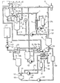
- the single figure of the drawing shows a device with a single-stage loop reactor, ie only a single loop reactor, the loop or primary circuit 1 of which is formed by a reaction vessel 3, namely an autoclave and a loop line 5.
- the latter connects one in the bottom of the container 3 available opening via a liquid pump 7 and a heat transfer element 11, namely a primary circuit heat exchanger, with the one input port 13a of an injector mixing nozzle 13, which opens into the top wall of the container 3 from above.
- a feed source 15 for a gaseous starting material, in particular hydrogen, is connected to an input connection 13b of the injector mixing nozzle 13 through a feed line 17, into which a shut-off and control valve 19 and a gas meter 21 are connected.
- the latter is designed similarly to a water jet pump, so that during operation of the device during the reaction phase it draws gas from line 17 and the gas atmosphere present in the uppermost part of container 3 and brings it into close contact with the liquid flowing through the nozzle.
- a catalyst feeder 23 is connected to the circuit 1 via a line 25.
- the line 25 opens into the section of the line 5 which connects the container 3 to the suction side of the pump 7. Add catalyst.
- the pump 7 is equipped in a known manner with two seals, one of which seals a gap between the two seals against the liquid pumped through the circuit 1 and the other seals the said gap against the environment.
- the space between the two seals is also known switched into a circuit, not shown, of a liquid serving as a barrier and coolant.
- the uppermost part of the interior of the container 3 is connected via a line 27 containing a check valve 29 to a vacuum suction pump 31 which, as indicated in the drawing, can be designed as a jet pump, for example.
- the heat transfer element 11 switched into the primary circuit is formed by a heat exchanger and, apart from its passage switched into the circuit 1, also has a passage, the ends of which are connected to a line forming a secondary circuit 33.
- this secondary circuit 33 which is only shown in simplified form, a pump 35 and a heat control element 37 are switched on.
- the latter has at least one cooler.
- the heat control element 37 may also be equipped with a heater and with valves in order to optionally switch the cooler or the heater into the secondary circuit, in which pressurized water is circulated during use.
- the cooler which in turn is designed as a heat exchanger, can be connected to connections 37a, 37b or connected to these via valves.
- the cooler can be switched into an external heating medium circuit via these connections 37a, 37b, so that the energy generated during the reaction phase and released via the heat transfer element 11 can be supplied to an external heat consumer.
- a condensate collection container is provided, which is designed and connected to the heat transfer element 11 in such a way that it supplies the latter with a liquid for cooling, which then evaporates and is collected again in the collecting container after condensation has taken place.
- the liquid, organic starting material required for carrying out the intended chemical reaction can be introduced into the container 3 from a feed source 41, shown schematically as a container, via a feed line 43, specifically in the upper interior part thereof.
- the intermediate container 57 is arranged above the junction of the feed line 43 into the reaction container 3 and the aforementioned junction is above the liquid level present in the container 3 during operation, so that the educt supplied from the intermediate container 57 in under the action of gravity the reaction container 3 can flow.
- the uppermost interior areas of the containers 51 and 57 are connected to the suction pump 31 via lines 61 and 63, in which a shut-off valve 65 and 67 is switched on.
- a derivation 71 serving to discharge the product formed from the circuit 1 branches off.
- a shut-off valve 73, a preferably heat-insulated intermediate container 75, which is expediently arranged below the circuit 1, a three-way valve 76, a pump 77, a passage 55b of the already mentioned heat exchanger 55, a passage 49b of the likewise already mentioned heat exchanger 49, an intermediate container 79, a three-way valve 81, a filter press pump 83 and a filter press 85 are switched on.
- the filter press 85 is connected via a line 89, a flow tank 91 and a check valve 93 to that section of the discharge line 71 which connects the three-way valve 81 to the pump 83.
- Another connection of the filter press 85 is connected to a line 95 from which the catalyst separated from the product can be removed. The separated catalyst, possibly after additional processing, can be brought back into the catalyst feeder 23 for reuse.
- the intermediate container 75 is connected via a line 97 to a check valve 99 with the suction pump 31.
- a connection of the three-way valve 81 is connected to a flushing agent reservoir 103 by a branch line 101.
- This has an outlet in the region of its base, which is connected to the three-way valve 76 via a line 105 into which a pump 107 and a heating element 109 are connected.
- the inlet of the pump 77 can optionally be connected to the container 75 or the heating element 109 via the valve 76.
- the valve 76 and / or the pumps 77 and 107 are designed such that the inflow to the heat exchanger passage 55b can be completely blocked. Otherwise, the two intermediate containers 57 and 75 are dimensioned in such a way that the container 57 can hold an entire educt batch and the container 75 can accommodate a product quantity formed from an entire educt batch.
- the circuit 1 is first evacuated with the suction pump 31.
- a first batch of nitrile is then introduced from the feed source 41 through the feed line 43 and the organs connected into the reaction container 3, so that the latter is filled to about 70%, for example. This results in a liquid level in the container, which lies below the mouth of the feed line 43.
- the nitrile supplied by the feed source 41 can, for example, have room temperature or possibly a certain storage temperature.
- the nitrile flows through the passages 49a and 55a of the two heat exchangers 49 and 55, among other things, during supply.
- liquid detergent is conveyed through the heating element 109 from the reservoir 103 at the same time.
- the detergent heated in the heating element 109 is then pumped by the pump 77 through the passages 55b and 49b of the heat exchangers 55 and 49 and then returns to the reservoir 103 via the container 79 and the valve 81.
- the flushing agent flowing through the heat exchangers 55 and 49 in countercurrent to the nitrile gives off heat to the nitrile.
- the flow rate and temperature of the flushing agent supplied by the pump 77 are matched to the flow rate and initial temperature of the nitrile in such a way that it reaches the degassing container at a temperature of approximately 110 ° C., where the volatile additives can escape and by means of the suction pump 31 are suctioned off. Thereafter, the nitrile is pumped through the passageway 55a of the heat exchanger 55, heating to a temperature of, for example, about 175 ° C.
- the valve 59 is closed and a second batch of nitrile is preheated with the heated washing-up liquid in the heat exchangers 49, 55, fed to the intermediate container 57 and stored therein.
- the nitrile of the first batch can be circulated by means of the pump 7 in the direction of the arrows in the circuit 1, the catalyst being metered into the nitrile from the catalyst feeder 23.
- hydrogen gas is also introduced into the container 3 from the feed source 15 through the mixing nozzle 13, so that a hydrogen atmosphere is created in the latter above the liquid level.
- the hydrogenation process can begin immediately when the nitrile and the catalyst added to it in the form of a suspension are circulated in the circuit 1.
- the liquid jet which arises during the circulation in the injector mixing nozzle 13 sucks in hydrogen from the hydrogen atmosphere present in the container 3 and brings this hydrogen into close contact with the nitrile, so that the chemical reaction takes place mainly in the mixing nozzle 13.
- the hydrogen consumed in the hydrogenation is subsequently supplied via the valve 19 and the gas meter 21, the supply being regulated in such a way that the intended operating pressure is maintained in the container 1.
- the circulated liquid in the heat transfer element 11 does not initially need to be supplied with heat or heat to be removed.
- the temperature of the circulated liquid increases after the start of the reaction process.
- the heat generated by the reaction is now dissipated in the heat transfer element 11 operating as a cooler by means of pressurized water circulating in the secondary circuit 33.
- the heat dissipation is regulated in such a way that the temperature is kept constant, for example at + 1 °, to a predetermined value which is in a size range around 200 °.
- the heat of reaction removed is given off in the cooler of the heat control member 37, for example to cooling water, or is removed by evaporating condensate.
- the heat can, if necessary, by means of the Steam are delivered to external heat consumers, which are connected to the connections 37a, 37b and together with the cooler belonging to the heat control element 37 form a further circuit.
- the hydrogen and catalyst feed are stopped and the crude product formed is removed from circuit 1 and a new starting material is added. Batch introduced into the cycle.
- the valve 73 is opened so that the liquid present in the circuit 1 can be drained off through the discharge line 71, the outflow being effected by the gas pressure present in the container 3 and partly by the pumps 7, 77 and 83 and partly caused by the action of gravity.
- the liquid product present in the container 3 and practically the entire product 1 is at least substantially completely drained off.
- the liquid is drained apart from any liquid residues adhering to the walls of the components forming the circuit, so that at least 90%, expediently at least 95% and for example at least 99% of the liquid previously circulated in the circuit is derived therefrom.
- the product first arrives in the intermediate container 75, where it is stored and degassed.
- the reaction container 3 is emptied, it is filled with a fresh, namely the second, preheated feed batch from the intermediate container 57.
- the intermediate container 57 is empty, it flows out of the first raw material batch formed, stored in the intermediate container 75, then through the passage 55b of the heat exchanger 55 and then through the passage 49b of the heat exchanger 49 into the intermediate container 79.
- the feed source 41 becomes liquid starting material for the third batch pumped through passages 49a and 55a of heat exchangers 49 and 55.
- the product flows through the two heat exchangers 55, 49 in countercurrent to the educt, with heat being transferred from the crude product to the liquid educt.
- the product enters the heat exchanger 55 at a temperature of approximately 200 ° C., is cooled as it flows through it to approximately 130 ° C., then reaches the heat exchanger 49 at this temperature and is cooled again in it, so that it has a Temperature of about 80 ° reaches the intermediate container 79.
- the reactant as it flows through the first heat exchanger 49 is heated by, for example, room temperature to about 110 ° C, can be degassed in the container 51, is heated in the second heat exchanger 55, for example, 175 0 and then stored in the intermediate container 57th
- the circuit 1, and in particular the reaction container 3, must first be completely emptied and possibly evacuated before the new educt batch is introduced. This is made possible by temporarily storing the liquid educt in the intermediate container 57 and the product or a part thereof in the intermediate container 75 when the batch is changed.
- the new educt batch When the new educt batch reaches the reaction container, it already has the minimum temperature or preferably the optimum temperature required to initiate the hydrogenation, so that a hydrogenation process can be started again immediately and carried out in the manner already described .
- the raw product derived from the circuit 1 is cooled to approximately 80 ° C. when it flows through the heat exchanger 49. This temperature is sufficiently low to be able to feed the raw product to the filter press 85.
- the filter press 85 which has a rotatable spindle, the desired pure product, i.e. the amine, separated from the catalyst.
- the filtration proceeds in a known manner step by step, the initial liquid, which still contains admixture, reaches the preliminary tank 91 and is then filtered again.
- the pure product obtained during filtration, i.e. the amine can then be removed via line 87 and passed on for further use.
- the catalyst obtained in the filtration can be removed via line 95 and reused.
- This filtration of the crude product formed from a nitrile batch can take place during the period in which the new nitrile batch is hydrogenated.
- the second last batch of starting material has been converted into the product and is derived from the container 3, no new starting material per se would have to be fed to the intermediate container 57.
- a cooling liquid can be passed through the heat exchanger passages 49a, 55a into the intermediate container 57 and then derive again through the reaction container 3.
- the starting material which is then no longer reacted in the reaction container, or another liquid which simultaneously serves as a rinsing agent can be used as the cooling liquid. It is generally not necessary to cool this cooling liquid, but if necessary it can be done, for example, by means of the heat transfer element 11.
- the device according to the invention has the advantage over a known device intended for batch operation that the reaction container 3 can be smaller. Accordingly, other components of the device according to the invention can also be made smaller. Furthermore, in the process according to the invention, apart from the energy required to heat the first two batches of starting material, no energy from external sources is required to react the liquid starting material heat temperature. While in the previously known process using cooling water during the course of the reaction, the reaction heat generated has to be removed and the crude product then also has to be cooled to filtration temperature using cooling water, the crude product is cooled to the filtration temperature in the process according to the invention, at least when one of the last two batches is used in a series without the need for cooling water. Accordingly, the cooling water consumption in the method according to the invention is considerably smaller, and the heat released during the reaction phase can also be used in external consumers.
- the main advantage of the method according to the invention is that the total time required for processing a batch is significantly reduced, which then allows a smaller reaction container to be used.
- 10 minutes are required per batch for filling the liquid starting material into the container, 74 minutes for carrying out the reaction, 10 minutes for emptying and any evacuation and possibly a maximum of 15 minutes for any rinsing. This results in a total time of 94 to 109 minutes.
- each of the passages 49a, 49b, 55a, 55b mentioned can of course be formed from a number of parallel partial passages. Since it is also to be expected that catalyst will precipitate out of the crude product in the passages 55b, 49b and will settle, the heat exchangers 49, 55 are advantageously designed such that they can be disassembled for cleaning.
- the heat exchangers 49, 55 can, for example, have a housing which can be dismantled, in which a number of plates delimiting the passages are detachably held. It should also be noted in this connection that the risk of a catalyst precipitate forming in the heat transfer element 11 is significantly less than in the heat exchangers 49, 55 because the flow rate in the heat transfer element 11 is greater than in the heat exchangers 49 and 55.
- the device according to the invention can of course not only be used for the described hydrogenation of a nitrile, but also for a large number of other chemical reactions in which a liquid, organic starting material and a gaseous starting material are reacted.
- a large number of hydrogenations and ethoxylations, nitrations with N0 2 and carbonylations should be mentioned here.
- the liquid temperatures resulting from the heat transfer in the heat exchangers 49 and 55 can, of course, be different for different chemical reactions, or can be defined.
- the liquid educt supplied from the feed source 41 is heated in the first heat exchanger to a temperature of at least 80 ° C. and at most 130 ° C.
- the starting material supplied is then to be heated at least to the temperature which is advantageous for triggering the intended reaction.
- the product derived from the cycle when changing batches should, essentially with the exception of the last two batches in a batch series, exclusively through the heat exchange with the liquid educt cooled from the temperature at the end of the reaction phase to a temperature that allows filtration in the filter press.
- the product is therefore cooled after the heat exchange to a temperature which is at most 110 ° C, and preferably at most 90 ° C.
- the passage or conveyance of the liquid starting material and the liquid product through the two heat exchangers 49, 55 which preferably takes place at least partly at the same time as a reaction in the circuit 1, is to be determined and / or controlled in such a way that the starting material and the product are approximately the same need the same amount of time to pass through the two heat exchangers. It can thereby be achieved that at least 90%, preferably 95% and, for example, 100% of a product batch, passes at least one of the two heat exchangers 49, 55 simultaneously with the educt and can give off heat to it. Conversely, it can also be achieved that at least 90%, preferably at least 95% and, for example, 100% of a feed batch can take heat from the product in at least one of the two heat exchangers.
- the device is preferably provided with a control device which automatically controls the work sequences described and in particular opens and closes the valves 45, 59, 73, 76, 81 and possibly regulates them and includes the pumps 7, 47, 53, 77, 83, 107 and switches off and possibly regulates.
- a control device which automatically controls the work sequences described and in particular opens and closes the valves 45, 59, 73, 76, 81 and possibly regulates them and includes the pumps 7, 47, 53, 77, 83, 107 and switches off and possibly regulates.
- the facility is primarily intended for the batchwise implementation of exothermic reactions. However, it is also possible per se to carry out endothermic reactions, in which case the cycle 1 circulating liquid must be supplied during the reaction phase by means of the heat transfer element 11.
- the first and the second feed batch can be heated with a flushing and heating agent passed through them in countercurrent when they flow through the two heat exchangers 49, 55.
- the first two batches of educt could also be introduced cold into the container 3 and circulated during and after the introduction in the initially still evacuated, hydrogen-free circuit 1 and thereby heat them with the heat transfer element 11.
- hydrogen can be introduced and the reaction can thereby be triggered, in which case the heat transfer element 11 is used for cooling. Since the heat transfer element 11 in this variant is only used first for heating in the first two batches and is then used exclusively for cooling, "runaway" of the reactor can also be reliably prevented in this variant.
- the three-way valve 76 could possibly be replaced by a branch-free shut-off or control valve and the line 105 could possibly be omitted.
- a pump could also be switched on in the supply line section connecting the intermediate container 57 to the reaction container 3. If a pump, if any, arranged there, in the idle state, tightly shuts off the supply line and / or if the supply line section between the pump and the container 3 projects upward above the liquid levels in the containers 3 and 57 Arch, a so-called gooseneck, could possibly eliminate the valve 59.
- the feed source 41 and the containers 51, 57, 75, one or the other of the pumps 47, 53 and 77 can possibly be dispensed with, the function of this pump then being controlled by the Gravity would be replaced.
- the intermediate container 75 were arranged above the circuit 1, a pump could, if necessary, be switched on in the discharge section between the circuit 1 and the intermediate container 75, the valve 73 possibly being omitted for this purpose.
- the heat exchanger 55 were arranged above the intermediate container 75, a valve for locking and releasing the discharge section connecting the container 75 to the heat exchanger 55 could possibly be dispensed with.
- the intermediate container 57 could possibly remove either the intermediate container 57 or the intermediate container 75 to let. If, for example, the intermediate container 57 were not present, a product batch present in the circuit 1 could first be derived in the intermediate container 75 when the batch is changed. After the circuit 1 has been emptied, the product batch could be passed from the intermediate container 75 through the heat exchangers 49, 55 and at the same time the new starting material batch could be introduced directly into the circuit 1 through the heat exchanger.
- the feed line for the liquid educt and the product discharge line can of course be connected to the loop reactor circuit at other points than was shown in the drawing and previously described.
- the supply line and the discharge line could then be routed via at least one heat exchanger, an intermediate container and further means, such as valves and / or pumps, being able to be connected in the supply line and / or the discharge line in order to ensure heat exchange between the batches to enable the supplied liquid educt and the derived product.
- reaction vessel of the last loop reactor in terms of fluid fluid during batch changes as an intermediate container for the temporary product in the derivation of the upstream loop reactor.
- the reaction vessel of the fluidically first loop reactor could also be used during the batch changes as an intermediate vessel connected to the feed line to the subsequent loop reactor for the temporary storage of the starting material. If, in this way, certain reaction tanks are temporarily used as intermediate tanks during batch changes, the intermediate tanks connected between the heat exchanger and the first and last circuit in the supply or discharge can be used exclusively for temporary storage possibly smaller or possibly even omit at least one of these intermediate containers.
Landscapes
- Chemical & Material Sciences (AREA)
- Organic Chemistry (AREA)
- Chemical Kinetics & Catalysis (AREA)
- Physical Or Chemical Processes And Apparatus (AREA)
- Organic Low-Molecular-Weight Compounds And Preparation Thereof (AREA)
- Saccharide Compounds (AREA)
Abstract
Description
Die Erfindung betrifft eine Einrichtung gemäss dem Oberbegriff des Anspruchs 1.The invention relates to a device according to the preamble of claim 1.
Für die katalytische Hydrierung von flüssigen, organischen Edukten mit Wasserstoff und auch für andere chemische Reaktionen, bei denen ein flüssiges Edukt und ein gasförmiges Edukt zur Reaktion gebracht werden, verwendet man, insbesondere wenn grössere Produktemengen herzustellen sind, häufig Schleifenreaktoren. Derartige Schleifenreaktoren und Anwendungen davon sind unter anderem aus den schweizerischen Patentschriften 370 057 und 405 240, der österreichischen Patentschrift 287 890 sowie der Publikation "Loop Reactor Technology Improves Catalytic Hydrogenations" von R.J.Malone, Chemical Engineering Progress, Juni 1980, Seiten 53 bis 59 bekannt.Loop reactors are often used for the catalytic hydrogenation of liquid, organic starting materials with hydrogen and also for other chemical reactions in which a liquid starting material and a gaseous starting material are reacted, in particular when larger quantities of products are to be produced. Such loop reactors and applications thereof are known, inter alia, from Swiss Patents 370 057 and 405 240, Austrian Patent 287 890 and the publication "Loop Reactor Technology Improves Catalytic Hydrogenations" by RJMalone, Chemical Engineering Progress, June 1980,
Ein Schleifenreaktor der zurzeit gebräuchlichen Art weist einen Reaktions-Behälter auf, in den oben eine Injektor-Mischdüse hineinragt. Im Boden des Reaktions-Behälters ist ein Auslass vorhanden, der über eine Leitung, in die eine Umwälzpumpe und ein Wärmeaustauscher eingeschaltet ist, mit der Mischdüse verbunden ist. Der Behälter bildet also zusammen mit der erwähnten Leitung und den in diese eingeschalteten Organen einen Kreislauf. Durch in den Kreislauf mündende Zuleitungen kann diesem ein flüssiges Edukt, ein gasförmiges Edukt und ein Katalysator zugeführt werden.A loop reactor of the type currently in use has a reaction container into which an injector mixing nozzle projects. In the bottom of the reaction vessel there is an outlet which is connected to the mixing nozzle via a line into which a circulation pump and a heat exchanger are connected. The container therefore forms a circuit together with the line mentioned and the organs connected to it. A feed line, a gaseous starting material and a catalyst can be fed to the circuit through feed lines.
Das bei der Reaktion gebildete Produkt kann durch eine vom Kreislauf abgezweigte Ableitung entnommen werden.The product formed in the reaction can be removed by a branch branched off from the circuit.
Nun soll anhand eines Beispiels, nämlich der Hydrierung eines Nitrils, die Arbeitsweise eines bekannten Schleifenreaktors erläutert werden. Zunächst wird der Behälter gespült und danach eine Charge, d.h. eine bestimmte vorgegebene Menge des Nitrils in den Behälter eingebracht und im Kreislauf zirkuliert. Dem in den Kreislauf eingeschalteten Wärmeaustauscher wird dabei durch einen sekundären Kreislauf Wärme zugeführt, wobei im Sekundär-Kreislauf ein Wärmeträger, zum Beispiel Wasserdampf bzw. flüssiges Wasser zirkuliert wird. Das Nitril wird beim Passieren des Wärmeaustauschers aufgewärmt und nötigenfalls getrocknet und mittels einer mit dem Behälter verbundenen Saugvorrichtung entgast. Ferner wird nun gasförmiger Wasserstoff zugeführt, so dass im oberen Teil des Behälters eine Wasserstoffatmosphäre vorhanden ist, und auch der Katalysator in den Kreislauf eingebracht. Wenn die zirkulierende Flüssigkeit auf eine gewisse, im Bereich von 150 bis 170 C liegende Temperatur aufgeheizt ist, setzt die chemische Reaktion ein. Die chemische Reaktion läuft dabei vor allem im Bereich der Mischdüse ab, die ähnlich wie eine Wasserstrahlpumpe ausgebildet ist und Wasserstoff ansaugt sowie in engen Kontakt mit der Flüssigkeit bringt.The operation of a known loop reactor will now be explained using an example, namely the hydrogenation of a nitrile. First the container is rinsed and then a batch, i.e. a certain predetermined amount of the nitrile is introduced into the container and circulated. The heat exchanger connected to the circuit is supplied with heat by a secondary circuit, a heat carrier, for example water vapor or liquid water, being circulated in the secondary circuit. The nitrile is warmed up as it passes through the heat exchanger and, if necessary, dried and degassed by means of a suction device connected to the container. Furthermore, gaseous hydrogen is now supplied, so that a hydrogen atmosphere is present in the upper part of the container, and the catalyst is also introduced into the circuit. When the circulating liquid is heated to a certain temperature in the range of 150 to 170 C, the chemical reaction begins. The chemical reaction mainly takes place in the area of the mixing nozzle, which is designed like a water jet pump and draws in hydrogen and brings it into close contact with the liquid.
Da die Reaktion exotherm ist, wird es bald nach dem Einsetzen der Reaktion notwendig, den Kreislauf zu kühlen. Zu diesem Zweck wird der in den Kreislauf eingeschaltete Wärmeaustauscher auf Kühlbetrieb umgeschaltet, wozu dem Wärmeaustauscher durch den Sekundär- Kreislauf kaltes Wasser zugeführt wird.Since the reaction is exothermic, it becomes necessary to cool the circuit soon after the onset of the reaction. For this purpose, the heat exchanger switched into the circuit is switched to cooling mode, for which cold water is supplied to the heat exchanger through the secondary circuit.
Wenn die ganze Nitril-Charge hydriert ist, wird das entstandene, flüssige Produkt, im vorliegenden Fall ein Amin, noch während einer gewissen Zeit im Kreislauf zirkuliert und abgekühlt. Wenn die Temperatur auf eine die Filtration ermöglichenden Wert abgesunken ist, wird das Produkt durch die Ableitung aus dem Kreislauf in einen Filtrations-Zwischenbehälter abgeleitet und danach mit einer Filterpresse filtriert und vom Katalysator getrennt.When the entire batch of nitrile is hydrogenated, the resulting liquid product, in the present case, becomes a Amine, circulated and cooled for a period of time. When the temperature has dropped to a level that enables filtration, the product is drained from the circuit into a filtration intermediate container and then filtered with a filter press and separated from the catalyst.
In der vorgängig zitierten Publikation von R.J. Malone ist als Anwendungsbeispiel eines Schleifenreaktors die Bildung von 2-Chloranisidin durch Hydrieren erwähnt. Bei einem für eine Jahresproduktion von 1800 Tonnen konzipierten Schleifenreaktor dauert ein für die Verarbeitung einer Charge erforderlicher Zyklus insgesamt 164 Minuten. Dabei erfordert das Evakuieren und Spülen des Behälters 15 Minuten, das Einfüllen des flüssigen Edukts 10 Minuten, die Zugabe des Katalysators 5 Minuten, das Aufheizen 20 Minuten, die Durchführung der Reaktion 74 Minuten, das Abkühlen 30 Minuten und das Ableiten des gebildeten Produktes 10 Minuten. Beim Betrieb des aus der genannten Publikation bekannten Schleifenreaktors beträgt also die für die Verarbeitung einer Charge insgesamt benötigte Zeit mehr als das Doppelte der eigentlichen Reaktionszeit. Ein so grosses Verhältnis der gesamten Verarbeitungszeit zur eigentlichen Reaktionszeit ist natürlich unerwünscht und macht bei einer vorgegebenen Jahresproduktionsrate die Verwendung eines relativ grossen Behälters notwendig. Bei der Herstellung vieler anderer Produkte aus einem flüssigen und einem gasförmigen Edukt ergeben sich ähnliche Verhältnisse.In the previously cited publication by R.J. Malone mentions the formation of 2-chloroanisidine by hydrogenation as an application example of a loop reactor. With a loop reactor designed for an annual production of 1800 tons, a cycle required for processing one batch takes a total of 164 minutes. The evacuation and rinsing of the container takes 15 minutes, the filling in of the liquid starting material 10 minutes, the addition of the
Ein anderer Nachteil des vorbekannten Schleifenreaktors besteht auch noch darin, dass zum Aufheizen des flüssigen Eduktes auf die zum Auslösen der Reaktion erforderliche Temperatur eine beträchtliche Energiemenge erfoderlich ist. Diese wird von einer äusseren Energiequelle aufgebracht und kann grosse Kosten verursachen.Another disadvantage of the previously known loop reactor is that a considerable amount of energy is required to heat the liquid starting material to the temperature required to initiate the reaction is required. This is generated by an external energy source and can cause great costs.
Da viele der in Schleifenreaktoren durchgeführten Reaktionen, wie die erwähnten Hydrierungen, exotherm verlaufen, muss die im Kreislauf zirkulierende Flüssigkeit, wie bereits dargelegt, im Wärmeaustauscher bis zum Einsetzen der Reaktion erwärmt und danach gekühlt werden. Bei gewissen Reaktionen setzt die Wärmeabgabe ziemlich schlagartig und heftig ein, so dass der Wärmeaustauscher entsprechend schnell vom Heizbetrieb auf den Kühlbetrieb umgeschaltet werden sollte. Diese Umschaltung vom Heiz- auf den Kühlbetrieb wird jedoch dadurch verzögert, dass der Wärmeaustauscher und Teile des damit verbundenen SekundärKKreislaufes eine gewisse Wärmekapazität aufweisen und zuerst selbst abgekühlt werden müssen. Wenn also der in den Kreislauf eingeschaltete Wärmeaustauscher zuerst Wärme zuführen und danach Wärme abführen muss, bringt dies die Gefahr mit sich, dass die Temperatur beim Einsetzen der Reaktion unerwünscht hoch ansteigt. Dieses wiederum kann zur Folge haben, dass die Reaktionsgeschwindigkeit zu gross wird und die Kontrolle über den Reaktionsablauf verloren geht, so dass der Reaktionsvorgang gewissermassen "durchgeht", wobei die Gefahr besteht, dass unerwünschte Nebenprodukte entstehen, die sehr toxisch sein und/oder zur Explosion neigen können.Since many of the reactions carried out in loop reactors, such as the hydrogenations mentioned, are exothermic, the liquid circulating in the circuit, as already explained, must be heated in the heat exchanger until the reaction begins and then cooled. With certain reactions, the heat is emitted quite suddenly and violently, so that the heat exchanger should be switched from heating to cooling mode accordingly quickly. However, this switchover from heating to cooling operation is delayed by the fact that the heat exchanger and parts of the associated secondary circuit have a certain heat capacity and must first be cooled themselves. So if the heat exchanger that is switched on in the circuit first has to supply heat and then remove heat, this entails the risk that the temperature will rise undesirably high when the reaction starts. This, in turn, can result in the reaction speed becoming too high and control over the course of the reaction being lost, so that the reaction process "passes through" to a certain extent, with the risk that undesirable by-products are formed which are very toxic and / or explode can tend.
Aus der Publikation "Funktionseinheiten zur katalytischen Hydrierung und Reduktion" vom Mai 1972 der Buss AG, Basel ist eine Hydrierungs-Einrichtung bekannt, die eine aus mindestens zwei hintereinander geschalteten Schleifenreaktoren gebildete Kaskade aufweist. Jeder Schleifenreaktor weist einen Behälter und eine mit diesem zusammen einen Kreislauf bildende Leitung auf, die vom Boden des Behälters über eine Umwälzpumpe und einen Wärmeaustauscher zu einer wieder in den Behälter mündenden Mischdüse führt. Das flüssige Edukt wird dem ersten Schleifenreaktor über einen Wärmeaustauscher zugeführt. In der Anlaufphase wird die Reaktionsflüssigkeit im Kreislauf durch die ganze Kaskade zirkuliert und in den zu den einzelnen Schleifenreaktoren gehörenden Wärmeaustauschern erhitzt, bis die Reaktionstemperatur erreicht ist. Danach kann die Einrichtung kontinuierlich arbeiten, wobei die Reaktionsflüssigkeit der Reihe nach die zwei oder mehr Schleifenreaktoren durchläuft. Das gebildete Produkt wird vom zweiten bzw. letzten Schleifenreaktor über eine Ableitung und einen Durchgang des Wärmeaustauschers, über den das Edukt dem ersten Schleifenreaktor zugeführt wird, einem Entgasungsbehälter zugeführt. Von diesem wird es dann zu einem Filter weitergeleitet.From the publication "Functional Units for Catalytic Hydrogenation and Reduction" from May 1972 by Buss AG, Basel, a hydrogenation device is known which has a cascade formed from at least two loop reactors connected in series. Each loop reactor has a container and a conduit which forms a circuit together with it Bottom of the container leads via a circulation pump and a heat exchanger to a mixing nozzle which opens into the container again. The liquid educt is fed to the first loop reactor via a heat exchanger. In the start-up phase, the reaction liquid is circulated through the entire cascade and heated in the heat exchangers belonging to the individual loop reactors until the reaction temperature is reached. The device can then operate continuously, with the reaction liquid passing through the two or more loop reactors in sequence. The product formed is fed from the second or last loop reactor via a discharge line and a passage of the heat exchanger via which the starting material is fed to the first loop reactor to a degassing tank. From there it is forwarded to a filter.
Eine derartige, mit mindestens zwei Schleifenreaktoren ausgerüstete Einrichtung kann an sich nach der erwähnten Anlaufphase kontinuierlich arbeiten. Bei der praktischen Anwendung von Schleifenreaktoren werden diese jedoch meistens abwechselnd für die Herstellung verschiedener Produkte verwendet und sind im allgemeinen höchstens einige wenige Tage ununterbrochen in Betrieb. Dementsprechend ergeben sich häufig Betriebsunterbrüche, wobei dann bei jeder Wiederaufnahme des Betriebes zuerst eine Anlaufphase notwendig wird.Such a device, equipped with at least two loop reactors, can in itself work continuously after the start-up phase mentioned. In the practical application of loop reactors, however, these are mostly used alternately for the production of different products and are generally only in operation for a few days at a time. Accordingly, there are often business interruptions, with a start-up phase being necessary each time business is resumed.
Bei einem Produktewechsel müssen die mit dem Produkt in Berührung gelangenden Teile sauber gereinigt werden. Bei Einrichtungen mit zwei oder mehr Schleifenreaktoren muss natürlich jeder Schleifenreaktor gereinigt werden, so dass der Aufwand für die Reinigung verhältnismässig gross wird.When changing products, the parts that come into contact with the product must be cleaned properly. In the case of devices with two or more loop reactors, each loop reactor must of course be cleaned, so that the cleaning effort is relatively great.
Des weitern ist bei Einrichtungen mit einer Kaskade von Schleifenreaktoren auch der apparative Aufwand grösser als bei einer Einrichtung mit einem einzelnen, diskontinuierlich betriebenen Schleifenreaktor. Hier ist insbesondere darauf hinzuweisen, dass die in die Kreisläufe der Reaktions-Schleifen eingeschaltenen Pumpen sehr leistungsfähig sein und starken Beanspruchungen widerstehen müssen.Furthermore, equipment with a cascade of loop reactors also requires more equipment than equipment with a single, discontinuously operated loop reactor. It should be pointed out here in particular that the pumps switched into the circuits of the reaction loops have to be very powerful and have to withstand heavy loads.
Eine für den kontinuierlichen Betrieb vorgesehene Einrichtung mit zwei oder mehr Schleifenreaktoren ist daher sowohl was die Herstellungskosten als auch was die Betriebskosten anbelangt, im allgemeinen teurer als eine für den Chargen-Betrieb vorgesehene, nur einen SchleifenReaktor aufweisende Einrichtung mit gleicher mittlerer Produktionsleistung. In der Praxis werden daher nur verhältnismässig selten Einrichtungen mit Kaskaden von Schleifenreaktoren eingesetzt.A device intended for continuous operation with two or more loop reactors is therefore generally more expensive, both in terms of production costs and operating costs, than a device intended for batch operation and having only one loop reactor with the same average production output. In practice, devices with cascades of loop reactors are therefore used only relatively rarely.
In der US-Patentschrift 2 232 674 ist eine Einrichtung für die Durchführung chemischer Reaktionen von flüssigen Edukten, insbesondere für die Alkylierung von Isoparaffinen mit Olefinen, geoffenbart. Die Einrichtung weist eine einen Kreislauf bildende Leitung auf, in die ein Tank mit perforierten Platten eingeschaltet ist. Ein Teil der im Kreislauf zirkulierenden Flüssigkeit wird durch eine Temperatur-Regeleinheit hindurch geführt, die je nach Bedarf als Heizer oder Kühler ausgebildet sein kann. Die verschiedenen Edukte werden über eine gemeinsame Zuleitung, einen Wärmeaustauscher, eine zur Abscheidung unerwünschter Komponenten, wie Wasser, dienenden Vorrichtung und einen Mischer dem Kreislauf zugeführt. Das im Kreislauf gebildete Produkt wird über eine Ableitung, einen Separator, den bereits erwähnten Wärmeaustauscher und einen weitern Separator abgeleitet.US Pat. No. 2,232,674 discloses a device for carrying out chemical reactions of liquid starting materials, in particular for the alkylation of isoparaffins with olefins. The device has a circuit which forms a circuit and into which a tank with perforated plates is connected. Part of the liquid circulating in the circuit is passed through a temperature control unit, which can be designed as a heater or cooler as required. The various educts are fed to the circuit via a common feed line, a heat exchanger, a device used to separate undesired components, such as water, and a mixer. The product formed in the circuit is discharged via a discharge line, a separator, the already mentioned heat exchanger and a further separator.
Gemäss der US-Patentschrift 2 232 674 wird diese bekannte Einrichtung offensichtlich kontinuierlich betrieben. Die Einrichtung wäre jedoch auch gar nicht für einen chargenweisen Betrieb geeignet, weil es nämlich nicht möglich wäre, im Wärmeaustauscher einen Wärmeaustausch zwischen dem abgeleiteten Produkt und den zugeführten Edukten vorzunehmen, wenn das Produkt aus dem Kreislauf abgeleitet würde, bevor die Edukte zugeführt werden.According to US Pat. No. 2,232,674, this known device is obviously operated continuously. However, the device would not be suitable for batch operation at all, because it would not be possible to carry out a heat exchange in the heat exchanger between the derived product and the educts supplied if the product were derived from the circuit before the educts are supplied.
Die kontinuierliche Arbeitsweise der Einrichtung gemäss der US-Patentschrift 2 232 674 bringt ferner den Nachteil mit sich, dass das aus dem Kreislauf abgeleitete Produkt noch einen Anteil Edukte enthält, die in den erwähnten Separatoren abgetrennt und wieder dem Kreislauf zugeführt werden müssen. Im übrigen ist die Einrichtung weder ausgerüstet noch geeignet, um ein gasförmiges Edukt in den Kreislauf einzuführen und in diesem mit einem flüssigen Edukt zur Reaktion zu bringen.The continuous operation of the device according to US Pat. No. 2,232,674 also has the disadvantage that the product derived from the circuit still contains a proportion of starting materials which have to be separated off in the separators mentioned and fed back into the circuit. In addition, the device is neither equipped nor suitable for introducing a gaseous educt into the circuit and for reacting it in the circuit with a liquid educt.
Aus der englischen Patentschrift 1 130 330 ist ein Reaktor für die Phenol-Formaldehyd-Harz-Herstellung bekannt. Die Einrichtung weist einen Tank für die Speicherung einer Phenol-Formaldehyd-Mischung, einen Vorheiz-Kreislauf, einen Reaktor-Kreislauf, einen Kühl-Kreislauf und ein Auslass-System auf. Der Tank, die drei Kreisläufe und das Auslass-System sind in dieser Reihenfolge miteinander verbunden und in jeden Kreislauf ist ein Wärmeaustauscher und ein Ventil eingeschaltet. Ferner ist ein Temperatur-Regelsystem vorhanden, das mit Durchgängen der Wärmeaustauscher des Vorheiz- und des Reaktor-Kreislaufs verbunden ist. Beim Betrieb wird das Phenol-Formaldehyd-Gemisch in den Kreisläufen zirkuliert und chargenweise weitergeleitet.A reactor for the production of phenol-formaldehyde resin is known from the English patent specification 1 130 330. The device has a tank for storing a phenol-formaldehyde mixture, a preheating circuit, a reactor circuit, a cooling circuit and an outlet system. The tank, the three circuits and the outlet system are connected in this order and a heat exchanger and a valve are switched on in each circuit. There is also a temperature control system which is connected to passages of the heat exchangers of the preheating and reactor circuits. During operation, the phenol-formaldehyde mixture is circulated in the circuits and forwarded in batches.
Bei dieser bekannten Einrichtung ist kein sowohl von einem zugeführten Edukt als auch von einem abgeleiteten Produkt durchströmter Wärmeaustauscher vorhanden. Insbesondere wird das Produkt nach der Reaktion offensichtlich im erwähnten Kühlkreislauf gekühlt, von dem Wärme nach aussen abgeführt und nicht auf das Edukt übertragen wird. Es wäre also allerhöchstens möglich, dass mit dem erwähnten Temperatur-Regelsystem Wärme von dem in den Reaktor-Kreislauf eingeschalteten Wärmeaustauscher zu dem in den Vorheiz-Kreislauf eingeschalteten Wärmeübertrager und damit von den im Reaktor-Kreislauf zirkulierenden Substanzen auf das Edukt-Gemisch übertragen wird.In this known device, there is no heat exchanger through which both a feed material and a derived product flow. In particular, the product is obviously cooled in the cooling circuit mentioned after the reaction, from which heat is dissipated to the outside and is not transferred to the starting material. It would therefore at most be possible for the temperature control system mentioned to transfer heat from the heat exchanger connected into the reactor circuit to the heat exchanger connected into the preheating circuit and thus from the substances circulating in the reactor circuit to the educt mixture.
Die aus der englischen Patentschrift 1 130 330 bekannte Einrichtung ist zudem sehr kompliziert und hat ähnliche Nachteile wie die vorgängig schon beschriebene, aus der Publikation der Buss AG bekannte, kontinuierlich arbeitende, eine Schleifenreaktor-Kaskade aufweisende Einrichtung. Im übrigen ist die Einrichtung gemäss der englischen Patentschrift 1 130 330 auch nicht ausgerüstet, um dem Reaktions-Kreislauf ein gasförmiges Edukt zuzuführen und dieses mit einem flüssigen Edukt zur Reaktion zu bringen.The device known from the English patent specification 1 130 330 is also very complicated and has similar disadvantages as the previously described device known from the publication of Buss AG, which works continuously and has a loop reactor cascade. In addition, the device according to the English patent specification 1 130 330 is also not equipped to supply a gaseous starting material to the reaction circuit and to react it with a liquid starting material.
Es sei auch noch auf die Schweizer-Patentschrift 359 819 verwiesen. Aus dieser ist eine Einrichtung für die selektive Härtung von ungesättigten Ölen und Fetten bekannt. Die Einrichtung weist einen Autoklav auf, der durch Zwischenwände in eine Reihe nebeneinander angeordneter Kammern unterteilt ist. Die Zwischenwände sind mit Überlauf-Öffnungen versehen, so dass das Öl beim Erreichen eines vorgegebenen Niveaus von einer Kammer in die nächste überströmen kann. Das zu härtende Öl wird der ersten Kammer über eine Öl-Zuleitung zugeführt, in die in der Strömungsrichtung gesehen der Reihe nach ein Dampferhitzer, ein Wärmeaustauscher und nochmals ein Dampferhitzer eingeschaltet sind. Zwischen dem Trockner und dem zweitgenannten Dampferhitzer mündet eine Katalysator-Speiseleitung in die Öl-Zuleitung.Reference is also made to the Swiss patent specification 359 819. From this a device for the selective hardening of unsaturated oils and fats is known. The device has an autoclave which is divided by partition walls into a row of chambers arranged side by side. The partitions are provided with overflow openings so that the oil can flow from one chamber to the next when a predetermined level is reached. The oil to be hardened is fed into the first chamber via an oil feed line Viewed in the direction of flow, a steam heater, a heat exchanger and another steam heater are switched on in sequence. A catalyst feed line opens into the oil feed line between the dryer and the second-mentioned steam heater.
Das der ersten Autoklav-Kammer zugeführte Öl strömt sukzessive durch die ganze Reihe der Autoklav-Kammern, wobei es in jeder Kammer in einem Kreislauf zirkuliert, der eine Umwälzpumpe, einen Kühler und einen Mischer aufweist. Von der letzten Kammer wird das Öl über eine Ableitung durch den bereits erwähnten Wärmeaustauscher einem mit einem Rührer ausgerüsteten Behälter zugeführt. Vom letzteren wird das Öl dann zu Filterpressen weitergeleitet. Im Wärmeaustauscher findet eine Wärmeübertragung von dem aus der letzten Kammer abgeleitete Öl auf das in die erste Kammer eingeleitete Öl statt.The oil supplied to the first autoclave chamber flows successively through the entire series of autoclave chambers, circulating in each chamber in a circuit which has a circulation pump, a cooler and a mixer. From the last chamber, the oil is fed to a container equipped with a stirrer via a discharge through the already mentioned heat exchanger. From the latter, the oil is then passed on to filter presses. In the heat exchanger, heat is transferred from the oil discharged from the last chamber to the oil fed into the first chamber.
Die aus der Schweizerpatentschrift 359 819 bekannte Einrichtung arbeitet also kontinuierlich. Da der Autoklav jedoch in eine relativ grosse Anzahl Kammern unterteilt ist, nämlich gemäss der Zeichnung in sechs Kammern, und da für jede dieser Kammern ein Kreislauf vorhanden sein muss, ist der apparative Aufwand für eine derartige Einrichtung sehr gross. Des weitern ist die Reinigung dieser Einrichtung, und insbesondere des in Kammern unterteilten Autoklavs, sehr schwierig und zeitraubend. Obschon ferner ein Teil der durch die chemischen Reaktionen erzeugten Wärme im erwähnten Wärmeaustauscher vom abgeleiteten Öl auf das zugeleitete Öl übertragen werden kann, muss das zugeleitete Öl zusätzlich noch in zwei Dampferhitzern erwärmt werden. Die Durchführung des Verfahrens erfordert also auch sehr viel von äusseren Energiequellen zugeführte Energie.The facility known from the Swiss patent 359 819 works continuously. However, since the autoclave is divided into a relatively large number of chambers, namely according to the drawing in six chambers, and since a circuit must be available for each of these chambers, the outlay on equipment for such a device is very great. Furthermore, cleaning this device, and especially the autoclave divided into chambers, is very difficult and time consuming. Furthermore, although part of the heat generated by the chemical reactions in the heat exchanger mentioned can be transferred from the derived oil to the supplied oil, the supplied oil must additionally be heated in two steam heaters. The implementation of the method therefore also requires a great deal of energy supplied by external energy sources.
Der Erfindung liegt nun ausgehend von der Einrichtung gemäss der US-Patentschrift 2 232 674 die Aufgabe zugrunde, eine Einrichtung mit einem Schleifenreaktor und einem Wärmeaustauscher mit in die Edukt-Zuleitung und die Produkt-Ableitung eingeschalteten Durchgängen zu schaffen, wobei die Einrichtung einen chargenweisen Betrieb ermöglichen soll.The invention is now based on the device according to US Pat. No. 2,232,674, the object of the invention is to provide a device with a loop reactor and a heat exchanger with passages switched into the educt feed line and the product discharge line, the device being intended to enable batch operation.
Diese Aufgabe wird durch eine Einrichtung der einleitend genannten Art gelöst, wobei die Einrichtung gemäss der Erfindung durch die Merkmale des Anspruchs 1 gekennzeichnet ist.This object is achieved by a device of the type mentioned in the introduction, the device according to the invention being characterized by the features of claim 1.
Zweckmässige Ausgestaltungen der Einrichtung ergeben sich aus den Ansprüchen 2 bis 6.Appropriate configurations of the device result from claims 2 to 6.
Die Erfindung betrifft ferner ein Verfahren gemäss dem Oberbegriff des Anspruchs 7. Das Verfahren ist erfindungsgemäss durch die Merkmale des Anspruchs 7 gekennzeichnet.The invention further relates to a method according to the preamble of claim 7. The method according to the invention is characterized by the features of claim 7.
Besonders zweckmässige Ausgestaltungen des Verfahrens gehen aus den Ansprüchen 8 bis 10 hervor.Particularly expedient refinements of the method emerge from claims 8 to 10.
Der Erfindungsgegenstand soll nun anhand eines in der Zeichnung dargestellten Ausführungsbeispiels erläutert werden. Die einzige Figur der Zeichnung zeigt ein Schema einer Einrichtung mit einem Schleifenreaktor.The object of the invention will now be explained with reference to an embodiment shown in the drawing. The only figure in the drawing shows a diagram of a device with a loop reactor.
In der einzigen Figur der Zeichnung ist eine Einrichtung mit einem einstufigen Schleifenreaktor, d.h. nur einem einzigen Schleifenreaktor ersichtlich, dessen Schleife bzw. Primär-Kreislauf 1 durch einen Reaktions-Behälter 3, nämlich einen Autoklav und eine Schleifen-Leitung 5 gebildet wird. Die letztere verbindet eine im Boden des Behälters 3 vorhandene Öffnung über eine Flüssigkeits-Pumpe 7 und ein Wärmeübertragungsorgan 11, nämlich einen Primär-Kreislauf-Wärmeaustauscher, mit dem einen Eingang-Anschluss 13a einer Injektor-Mischdüse 13, die bei der Deckwand des Behälters 3 von oben her in diesen einmündet.The single figure of the drawing shows a device with a single-stage loop reactor, ie only a single loop reactor, the loop or primary circuit 1 of which is formed by a
Eine Speisequelle 15 für ein gasförmiges Edukt, insbesondere Wasserstoff, ist durch eine Zuleitung 17, in die ein Sperr- und Regelventil 19 sowie Gaszähler 21 eingeschaltet ist, mit einem Eingangsanschluss 13b der Injektor-Mischdüse 13 verbunden. Die letztere ist ähnlich wie eine Wasserstrahlpumpe ausgebildet, so dass sie beim Betrieb der Einrichtung während der Reaktionsphase aus der Leitung 17 und der im obersten Teil des Behälters 3 vorhandenen Gas-Atmosphäre Gas ansaugt und in engen Kontakt mit der die Düse durchströmenden Flüssigkeit bringt.A feed source 15 for a gaseous starting material, in particular hydrogen, is connected to an
Ein Katalysator-Speiseorgan 23 ist über eine Leitung 25 mit dem Kreislauf 1 verbunden. Dabei mündet die Leitung 25 in den den Behälter 3 mit der Saugseite der Pumpe 7 verbindenden Abschnitt der Leitung 5. Das Sperr- und Dosiermittel, wie Ventile, aufweisende Katalysator-Speiseorgan 23 ermöglicht, der beim Betrieb im Kreislauf 1 zirkulierenden Flüssigkeit einen suspendierten Feststoff-Katalysator beizufügen.A
Die Pumpe 7 ist in bekannter Weise mit zwei Dichtungen ausgerüstet, von denen die eine einen zwischen den beiden Dichtungen vorhandenen Zwischenraum gegen die durch den Kreislauf 1 gepumpte Flüssigkeit und die andere den genannten Zwischenraum gegen die Umgebung abdichtet. Der zwischen den beiden Dichtungen vorhandene Zwischenraum ist in ebenfalls bekannter Weise in einen nicht dargestellten Kreislauf einer als Sperr- und Kühlmittel dienenden Flüssigkeit eingeschaltet.The pump 7 is equipped in a known manner with two seals, one of which seals a gap between the two seals against the liquid pumped through the circuit 1 and the other seals the said gap against the environment. The space between the two seals is also known switched into a circuit, not shown, of a liquid serving as a barrier and coolant.
Der oberste Teil des Innenraumes des Behälters 3 ist über eine ein Sperrventil 29 enthaltende Leitung 27 mit einer Vakuum-Saugpumpe 31 verbunden, die beispielsweise, wie in der Zeichnung angedeutet, als Strahlpumpe ausgebildet sein kann.The uppermost part of the interior of the
Das in den Primär-Kreislauf eingeschaltete Wärmeübertragungsorgan 11 ist, wie bereits erwähnt, durch einen Wärmeaustauscher gebildet und weist abgesehen von seinen in den Kreislauf 1 eingeschalteten Durchgang noch einen Durchgang auf, dessen Enden mit einer einen Sekundär- Kreislauf 33 bildende Leitung verbunden sind. In diesen nur vereinfacht dargestellten Sekundär-Kreislauf 33 ist eine Pumpe 35 und ein Wärmeregelorgan 37 eingeschaltet. Das letztere weist mindestens einen Kühler auf. Eventuell ist das Wärmeregelorgan 37 zusätzlich zum Kühler noch mit einem Erhitzer und mit Ventilen ausgestattet, um wahlweise den Kühler oder den Erhitzer in den Sekundär-Kreislauf einzuschalten, in dem bei der Benutzung Druckwasser zirkuliert wird. Der Kühler, der seinerseits wieder als Wärmeaustauscher ausgebildet ist, kann mit Anschlüssen 37a, 37b verbunden sein oder über Ventile mit diesen verbunden werden. Der Kühler kann über diese Anschlüsse 37a, 37b in einen externen Wärmemittel-Kreislauf eingeschaltet werden, so dass die während der Reaktionsphase anfallende und über das Wärmeübertragungsorgan 11 abgegebene Energie einem externen Wärmeverbraucher zugeführt werden kann.As already mentioned, the
Es sei jedoch bemerkt, dass anstelle des beschriebenen Sekundär-Kreislaufes ein Kondensatsammelbehälter vorhanden sein könnte, der derart ausgebildet und mit dem Wärmeübertragungsorgan 11 verbunden ist, dass er dem letzteren zum Kühlen eine Flüssigkeit zuführt, die dann verdampft und nach erfolgter Kondensation im Sammelbehälter wieder gesammelt wird.However, it should be noted that instead of the secondary circuit described, a condensate collection container is provided could be present, which is designed and connected to the
Das für die Durchführung der vorgesehenen chemischen Reaktion benötigte, flüssige, organische Edukt kann von einer schematisch als Behälter dargestellten Speisequelle 41 über eine Zuleitung 43 in den Behälter 3 eingeführt werden, und zwar in dessen oberen Innenraum-Teil. In die Zuleitung 43 ist, beginnend bei der Speisequelle 41, ein Ventil 45, eine Pumpe 47, ein Durchgang 49a eines ersten Wärmeaustauschers 49, ein Entgasungs- Behälter 51, eine Pumpe 53, ein Durchgang 55a eines zweiten Wärmeaustauschers 55, ein wärmeisolierter Zwischen-Behälter 57 und ein Ventil 59 eingeschaltet. Der Zwischen-Behälter 57 ist dabei oberhalb der Einmündung der Zuleitung 43 in den Reaktions-Behälter 3 angeordnet und die genannte Einmündung befindet sich oberhalb des beim Betrieb im Behälter 3 vorhandenen Flüssigkeitsniveaus, so dass das zugeführte Edukt unter der Einwirkung der Schwerkraft vom Zwischenbehälter 57 in den Reaktions-Behälter 3 strömen kann.The liquid, organic starting material required for carrying out the intended chemical reaction can be introduced into the
Die obersten Innenraum-Bereiche der Behälter 51 und 57 sind über Leitungen 61 bzw 63, in die ein Sperrventil 65 bzw. 67 eingeschaltet ist, mit der Saugpumpe 31 verbunden.The uppermost interior areas of the
Vom Kreislauf 1, nämlich von dem den Ausgang der Pumpe 7 mit dem Wärmeübertragungsorgan 11 und dem Behälter 3 verbindenden Abschnitt der Leitung 5, zweigt eine zum Ableiten des gebildeten Produks aus dem Kreislauf 1 dienende Ableitung 71 ab. In diese sind, beginnend von der Abzweigung aus dem Kreislauf 1 her, ein Sperrventil 73, ein vorzugsweise wärmeisolierter, sowie zweckmässigerweise unterhalb des Kreislaufs 1 angeordneter Zwischen-Behälter 75, ein Dreiwegventil 76, eine Pumpe 77, ein Durchgang 55b des bereits erwähnten Wärmeaustauschers 55, ein Durchgang 49b des ebenfalls bereits erwähnten Wärmeaustauschers 49, ein Zwischen-Behälter 79, ein Dreiwegventil 81, eine Filterpress-Pumpe 83 und eine Filterpresse 85 eingeschaltet. Durch die an einen Anschluss der letzteren angeschlossene Leitung 87 kann beim Betrieb das filtrierte, reine Produkt entnommen werden. Ein anderer Anschluss der Filterpresse 85 ist über eine Leitung 89, einen Vorlauf-Behälter 91 und ein Sperrventil 93 mit demjenigen Abschnitt der Ableitung 71 verbunden, der das Dreiwegventil 81 mit der Pumpe 83 verbindet. Ein anderer Anschluss der Filterpresse 85 ist mit einer Leitung 95 verbunden, aus der der aus dem Produkt abgeschiedene Katalysator entnommen werden kann. Der abgeschiedene Katalysator kann, eventuell nach einer zusätzlichen Aufbereitung, für die Wiederverwendung wieder in das Katalysator-Speiseorgan 23 gebracht werden. Der Zwischen-Behälter 75 ist über eine Leitung 97 mit einem Sperrventil 99 mit der Saugpumpe 31 verbunden.From the circuit 1, namely from the section of the
Ein Anschluss des Dreiwegventils 81 ist durch eine Zweigleitung 101 mit einem Spühlmittel-Reservoir 103 verbunden. Dieses weist im Bereich seines Bodens einen Auslass auf, der über eine Leitung 105, in die eine Pumpe 107 und ein Heizorgan 109 eingeschaltet sind, mit dem Dreiwegventil 76 verbunden ist. Der Einlass der Pumpe 77 kann über das Ventil 76 wahlweise mit dem Behälter 75 oder dem Heizorgan 109 verbunden werden. Dabei sind das Ventil 76 und/oder die Pumpen 77 und 107 derart ausgebildet, dass der Zufluss zum Wärmeaustauscher-Durchgang 55b vollständig gesperrt werden kann. Im übrigen sind die beiden Zwischen-Behälter 57 und 75 derart bemessen, dass der Behälter 57 eine ganze Edukt-Charge und der Behälter 75 eine aus einer ganzen Edukt-Charge gebildete Produktmenge aufnehmen können.A connection of the three-
Im folgenden soll die Arbeitsweise der Einrichtung erläutert werden. Dabei wird als Beispiel der Fall betrachtet, dass als gasförmiges Edukt Wasserstoff und als flüssiges Edukt aliphatisches Nitril zugeführt werden. Als Katalysator wird Nickel aufgeschlämmt. Das Nitril wird im Schleifenreaktor hydriert, so dass ein Amin entsteht.The operation of the facility will be explained below. The case is considered as an example where hydrogen is added as the gaseous starting material and aliphatic nitrile is added as the liquid starting material. Nickel is slurried as a catalyst. The nitrile is hydrogenated in the loop reactor so that an amine is formed.
Nun wird angenommen, der Reaktions-Behälter 3 sei wegen eines Betriebsunterbruches oder wegen eines Wechsels des herzustellenden Produktes vorgängig entleert worden, so dass also der Schleifenreaktor neu in Betrieb gesetzt werden muss. Dazu wird der Kreislauf 1 zunächst mit der Saugpumpe 31 evakuiert. Danach wird eine erste Charge Nitril aus der Speisequelle 41 durch die Zuleitung 43 und die in diese eingeschalteten Organe in den Reaktions-Behälter 3 eingeleitet, so dass dieser zu beispielsweise ungefähr 70 % gefüllt wird. Dabei ergibt sich im Behälter ein Flüssigkeits-Niveau, das unterhalb der Einmündung der Zuleitung 43 liegt. Das von der Speisequelle 41 gelieferte Nitril kann beispielsweise Raumtemperatur oder eventuell eine bestimmte Lagerungstemperatur aufweisen. Das Nitril strömt beim Zuführen unter anderem durch die Durchgänge 49a und 55a der beiden Wärmeaustauscher 49 bzw. 55.It is now assumed that the
Ferner wird gleichzeitig aus dem Reservoir 103 flüssiges Spülmittel durch das Heizorgan 109 hindurch gefördert. Das im Heizorgan 109 erhitzte Spülmittel wird dann durch die Pumpe 77 durch die Durchgänge 55b und 49b der Wärmeaustauscher 55 bzw. 49 hindurch gepumpt und gelangt danach über den Behälter 79 und das Ventil 81 in das Reservoir 103 zurück. Das die Wärmeaustauscher 55 und 49 im Gegenstrom zum Nitril durchströmende Spülmittel gibt Wärme an das Nitril ab. Die Durchflussmenge und Temperatur des durch die Pumpe 77 zugeführten Spülmittels sind dabei derart auf die Durchflussmenge und Anfangstemperatur des Nitrils abgestimmt, dass dieses mit einer Temperatur von ungefähr 110° C in den Entgasungs-Behälter gelangt, wo die leichtflüchtigen Beimengungen entweichen können und mittels der Saugpumpe 31 abgesaugt werden. Danach wird das Nitril durch den Durchgang 55a des Wärmeaustauschers 55 gepumpt, wobei es auf eine Temperatur von beispielsweise ungefähr 175° C erhitzt wird.Furthermore, liquid detergent is conveyed through the
Sobald die erste Nitril-Charge vollständig in den Reaktions-Behälter 3 eingebracht ist, wird das Ventil 59 geschlossen und eine zweite Nitril-Charge mit dem erhitzten Spülmittel in den Wärmeaustauschern 49, 55 vorgewärmt, dem Zwischenbehälter 57 zugeführt und in diesem gespeichert. Gleichzeitig kann das Nitril der ersten Charge mittels der Pumpe 7 in der Richtung der Pfeile im Kreislauf 1 zirkuliert werden, wobei dem Nitril aus dem Katalysator-Speiseorgan 23 dosiert Katalysator zugeführt wird. Nachdem nach der Evakuierung des Behälters 3 das Ventil 29 wieder geschlossen wurde, wird aus der Speisequelle 15 ferner durch die Mischdüse 13 hindurch Wasserstoffgas in den Behälter 3 eingeleitet, so dass im letzteren oberhalb des Flüssigkeitsniveaus eine Wasserstoff-Atmosphäre entsteht.As soon as the first batch of nitrile has been completely introduced into the
Da das Nitril in den Wärmeaustauschern 49, 55 auf eine zum Auslösen der Hydrierung ausreichend hohe Temperatur erhitzt wurde, kann der Hydrierungsvorgang sogleich beginnen, wenn das Nitril und der diesem in Form einer Suspension beigefügten Katalysator im Kreislauf 1 zirkuliert werden. Der bei der Zirkulation in der Injektor-Mischdüse 13 entstehende Flüssigkeitstrahl saugt dabei Wasserstoff aus der im Behälter 3 vorhandenen Wasserstoff-Atmosphäre an und bringt diesen Wasserstoff in engen Kontakt mit dem Nitril, so dass die chemische Reaktion hauptsächlich in der Mischdüse 13 stattfindet. Der bei der Hydrierung verbrauchte Wasserstoff wird dabei über das Ventil 19 und den Gaszähler 21 nachgeliefert, wobei die Zufuhr derart geregelt wird, dass im Behälter 1 der vorgesehene Betriebsdruck aufrechterhalten bleibt.Since the nitrile in the
Wenn der chemische Reaktionsvorgang gestartet wird, braucht der zirkulierten Flüssigkeit im Wärmeübertragungsorgan 11 zunächst weder Wärme zugeführt noch Wärme entnommen zu werden. Da die Hydrierung jedoch stark exotherm abläuft, erhöht sich nach dem Start des Reaktionvorganges die Temperatur der zirkulierten Flüssigkeit. Die durch die Reaktion erzeugte Wärme wird nun in dem als Kühler arbeitenden Wärmeübertragungsorgan 11 durch im Sekundärkreislauf 33 zirkulierendes Druckwasser abgeführt. Die Wärmeabfuhr wird dabei derart geregelt, dass die Temperatur auf beispielsweise + 1° genau auf einen vorgegebenen Wert konstant gehalten wird, der in einem um 200° liegenden Grössenbereich liegt. Die abgeführte Reaktionswärme wird im Kühler des Wärmeregelorgans 37 beispielsweise an Kühlwasser abgegeben, oder durch Verdampfen von Kondensat abgeführt. Die Wärme kann im Bedarfsfall mittels des Dampfes an externe Wärmeverbraucher abgegeben werden, die an die Anschlüsse 37a, 37b angeschlossen sind und zusammen mit dem zum Wärmeregelorgan 37 gehörenden Kühler einen weitern Kreislauf bilden.When the chemical reaction process is started, the circulated liquid in the
Sobald der Reaktionsvorgang abgeschlossen ist, d.h. wenn die ganze zuerst zugeführte Charge des flüssigen Eduktes in das gewünschte Produkt, nämlich in Amin umgewandelt wurde, werden die Wasserstoff- und Katalysatorzufuhr gestoppt und das gebildete Roh-Produkt aus dem Kreislauf 1 entnommen sowie eine neue Edukt-Charge in den Kreislauf eingebracht. Zur Entnahme des flüssigen, noch Katalysator-Beimengungen enthaltenden Roh-Produktes wird das Ventil 73 geöffnet, so dass die im Kreislauf 1 vorhandene Flüssigkeit durch die Ableitung 71 abgeleitet werden kann, wobei die Abströmung durch den im Behälter 3 vorhandenen Gasdruck und teils durch die Pumpen 7, 77 und 83 und teils durch die Einwirkung der Schwerkraft bewirkt wird. Dabei wird das im Behälter 3 und praktisch das im ganzen Kreislauf 1 vorhandene, flüssige Produkt mindestens im wesentlichen vollständig abgeleitet. Das heisst, die Flüssigkeit wird bis auf allenfalls an Wandungen der den Kreislauf bildenden Bauteile haftende Flüssigkeitsreste abgeleitet, so dass also mindestens 90 %, zweckmässigerweise mindestens 95 % und beispielsweise mindestens 99 % der vorher im Kreislauf zirkulierten Flüssigkeit aus diesem abgeleitet wird. Das Produkt gelangt beim Abströmen aus dem Kreislauf 1 zunächst in den Zwischen-Behälter 75, wo es gespeichert und entgast wird. Sobald der Reaktions-Behälter 3 entleert ist, wird er mit einer frischen, nämlich der zweiten vorgewärmten Edukt-Charge aus dem Zwischen-Behälter 57 gefüllt. Wenn der Zwischen-Behälter 57 leer ist, strömt das aus der ersten Edukt-Charge gebildete, im Zwischen-Behälter 75 gespeicherte Roh-Produkt dann durch den Durchgang 55b des Wärmeaustauschers 55 sowie danach durch den Durchgang 49b des Wärmeaustauschers 49 hindurch in den Zwischen-Behälter 79. Gleichzeitig wird aus der Speisequelle 41 flüssiges Edukt für die dritte Charge durch die Durchgänge 49a und 55a der Wärmeaustauscher 49 und 55 hindurchgepumpt.As soon as the reaction process is complete, ie when the entire batch of liquid starting material supplied first has been converted into the desired product, namely into amine, the hydrogen and catalyst feed are stopped and the crude product formed is removed from circuit 1 and a new starting material is added. Batch introduced into the cycle. To remove the liquid crude product which still contains admixtures of catalyst, the
Dabei durchströmt das Produkt die beiden Wärmeaustauscher 55, 49 im Gegenstrom zum Edukt, wobei Wärme vom Roh-Produkt auf das flüssige Edukt übertragen wird. Das Produkt tritt beispielsweise mit einer Temperatur von ungefähr 200° C in den Wärmeaustauscher 55 ein, wird beim Durchströmen von diesem auf ungefähr 130° C abgekühlt, gelangt dann mit dieser Temperatur in den Wärmeaustauscher 49 und wird darin nochmals abgekühlt, so dass es mit einer Temperatur von ungefähr 80° in den Zwischen-Behälter 79 gelangt. Umgekehrt wird das Edukt beim Durchströmen des ersten Wärmeaustauschers 49 von beispielsweise Raumtemperatur auf ungefähr 110° C erwärmt, kann im Behälter 51 entgast werden, wird im zweiten Wärmeaustauscher 55 auf beispielsweise 1750 erwärmt und danach im Zwischen-Behälter 57 gespeichert.The product flows through the two
Der Kreislauf 1, und insbesondere der Reaktions-Behälter 3, muss zuerst vollständig entleert und eventuell evakuiert werden, bevor die neue Edukt-Charge eingebracht wird. Dies wird dadurch ermöglicht, dass man beim Chargen-Wechsel das flüssige Edukt im Zwischenbehälter 57 und das Produkt oder einen Teil davon im Zwischen- Behälter 75 vorübergehend speichert.The circuit 1, and in particular the
Die folgenden Chargen-Wechsel werden in analoger Weise durchgeführt, wobei jeweils das aus der n-ten Edukt-Charge gebildete Produkt aus dem Kreislauf 1 in den Zwischen-Behälter 75 abgeleitet und danach die n+l-te Edukt-Charge aus dem Zwischen-Behälter 57 in den Reaktions-Behälter 3 eingefüllt wird. Während danach die n+l-te Edukt-Charge im Reaktions-Kreislauf 1 umgewandelt wird, erwärmt das aus der n-ten Edukt-Charge gebildete Produkt in den Wärmeaustauschern 49, 55 die n+2-te Edukt-Charge.The following batch changes are carried out in an analogous manner, the product formed from the n-th educt batch being derived from the circuit 1 into the
Wenn also die neue Edukt-Charge in den Reaktions-Behälter gelangt, so weist sie bereits die zum Auslösen der Hydrierung erforderliche Minimal-Temperatur oder vorzugsweise die optimale Temperatur auf, so dass sogleich wieder ein Hydrierungsvorgang gestartet und in der bereits beschriebenen Weise durchgeführt werden kann.When the new educt batch reaches the reaction container, it already has the minimum temperature or preferably the optimum temperature required to initiate the hydrogenation, so that a hydrogenation process can be started again immediately and carried out in the manner already described .
Das aus dem Kreislauf 1 abgeleitete Roh-Produkt wird, wie bereits erwähnt, beim Durchströmen des Wärmeaustauschers 49 auf ungefähr 80° C abgekühlt. Diese Temperatur ist ausreichend tief, um das Roh-Produkt der Filterpresse 85 zuführen zu können. In der eine drehbare Spindel aufweisenden Filterpresse 85 wird das gewünschte Rein-Produkt, d.h. das Amin, vom Katalysator getrennt. Die Filtration läuft dabei in bekannter Weise stufenweise ab, wobei die zuerst anfallende, noch Beimengung enthaltende Vorlauf-Flüssigkeit in den Vorlauf-Behälter 91 gelangt und danach nochmals filtriert wird. Das bei der Filtration gewonnene Rein-Produkt, d.h. das Amin, kann dann über die Leitung 87 entnommen und dem weitern Verwendungszweck zugeführt werden. Der bei der Filtration anfallende Katalysator kann über die Leitung 95 entnommen und wieder verwendet werden.As already mentioned, the raw product derived from the circuit 1 is cooled to approximately 80 ° C. when it flows through the
Diese Filtration des aus einer Nitril-Charge gebildeten Roh-Produktes kann während des Zeitraumes erfolgen, in welchem die neue Nitril-Charge hydriert wird.This filtration of the crude product formed from a nitrile batch can take place during the period in which the new nitrile batch is hydrogenated.
Wenn von einer Folge im wesentlichen unterbruchslos nacheinander verarbeiteten Chargen die zweitletzte Edukt-Charge in das Produkt umgewandelt worden ist und aus dem Behälter 3 abgeleitet wird, müsste an sich kein neues Edukt mehr zum Zwischen-Behälter 57 zugeführt werden. Da jedoch das aus der zweitletzten Edukt-Charge und danach auch das aus der letzten Charge gebildete Produkt ebenfalls noch gekühlt werden müssen, kann man zu diesem Zweck eine Kühlflüssigkeit durch die Wärmeaustauscher-Durchgänge 49a, 55a hindurch in den Zwischen-Behälter 57 leiten und danach wieder durch den Reaktions-Behälter 3 hindurch ableiten. Als Kühlflüssigkeit kann beispielsweise das Edukt, das dann im Reaktions-Behälter nicht mehr zur Reaktion gebracht wird, oder eine andere gleichzeitig als Spülmittel dienende Flüssigkeit verwendet werden. Eine Abkühlung dieser Kühlflüssigkeit dürfte im allgemeinen nicht erforderlich sein, kann aber nötigenfalls beispielsweise mittels des Wärmeübertragungsorganes 11 erfolgen.If from a sequence of batches processed one after the other essentially without interruption, the second last batch of starting material has been converted into the product and is derived from the
Im folgenden sollen anhand beispielsweiser Zahlenangaben einige charakteristische Grössen des erfindungsgemässen Verfahrens erörtert und mit den entsprechenden Grössen eines nicht erfindungsgemässen Verfahrens verglichen werden, das mit einem vorbekannten, nicht-erfindungsgemässen Schleifenreaktor durchgeführt werden kann, wie er beispielsweise in der bereits zitierten Publikation "Loop Reactor Technology Improves Catalytic Hydrogenations" von R.J. Malone beschrieben ist.In the following, some characteristic quantities of the method according to the invention are to be discussed on the basis of exemplary numerical data and compared with the corresponding quantities of a method not according to the invention, which can be carried out with a previously known loop reactor not according to the invention, as described, for example, in the publication "Loop Reactor Technology" already cited Improves Catalytic Hydrogenations "by RJ Malone is described.
Als Beispiel wird der Fall betrachtet, dass pro Tag eine Produktmenge von 100 Tonnen hergestellt wird. In der nachfolgenden Tabelle sind nun einige Grössen für die vorbekannte Einrichtung bzw. das erfindungsgemässe Verfahren angegeben. Dabei sind die Dampf- bzw. Kühlwassermengen angegeben, die bei ununterbrochenem Chargen-Betrieb für eine Tagesproduktion erforderlich sind, wobei die Sonderverhältnisse bei den zwei ersten und den zwei letzten Chargen nicht berücksichtigt werden. Im weitern gilt der angegebene Kühlwasserverbrauch unter der Annahme, dass entweder im Kühler des Wärmeregelorgans 37 oder direkt im Wärmeübertragungsorgan 11 Kühlwasser von ungefähr Raumtemperatur auf Siedetemperatur aufgewärmt und verdampft wird.

Wie aus der Tabelle ersehen werden kann, hat also die erfindungsgemässe Einrichtung gegenüber einer vorbekannten, für den chargenweisen Betrieb vorgesehene Einrichtung den Vorteil, dass der Reaktions-Behälter 3 kleiner sein kann. Dementsprechend können auch andere Bauteile der erfindungsgemässen Einrichtung kleiner bemessen werden. Ferner wird beim erfindungsgemässen Verfahren, wenn man von der zum Aufheizen der beiden ersten Edukt-Chargen erforderlichen Energie absieht, keine Energie von externen Quellen benötigt, um das flüssige Edukt auf Reaktionstemperatur aufzuheizen. Während beim vorbekannten Verfahren mittels Kühlwasser während des Reaktiorsablaufes die anfallende Reaktionswärme abgeführt und das Roh-Produkt danach ebenfalls mittels Kühlwasser noch auf Filtrationstemperatur abgekühlt werden muss, erfolgt das Abkühlen des Roh-Produktes auf Filtrationstemperatur beim erfindungsgemässen Verfahren, mindestens wenn man von den zwei letzten Chargen einer Serie absieht, ohne dass hierfür Kühlwasser benötigt wird. Dementsprechend ist der Kühlwasserverbrauch beim erfindungsgemässen Verfahren wesentlich kleiner, wobei die während der Reaktionsphase freigesetzte Wärme zudem noch in externen Verbrauchern verwendet werden kann.As can be seen from the table, the device according to the invention has the advantage over a known device intended for batch operation that the
Abgesehen von der möglichen Verkleinerung verschiedener Bauteile und der Verbesserung der Energiebilanz besteht jedoch der Hauptvorteil des erfindungsgemässen Verfahrens darin, dass die für die Verarbeitung einer Charge erforderliche Gesamtzeit wesentlich verkürzt wird, was dann eben erlaubt mit einem kleineren Reaktions-Behälter auszukommen. Beim erfindungsgemässen Verfahren werden pro Charge 10 Minuten für das Einfüllen des flüssigen Eduktes in den Behälter 3, 74 Minuten für das Durchführen der Reaktion, 10 Minuten für die Entleerung und allfällige Evakuation und eventuell noch im Maximum 15 Minuten für eine allfällige Spülung benötigt. Dies ergibt eine Gesamtzeit von 94 bis 109 Minuten. Beim vorbekannten Verfahren beträgt der Zeitaufwand pro Charge demgegenüber für die in der Einleitung erwähnte Cloranisidin-Herstellung, die was den eigentlichen Reaktionsablauf anbelangt, mit der Amin-Herstellung vergleichbar ist und wegen der kleineren, nur 900 C betragenden Reaktionstemperatur sogar nur eine geringere Edukt-Erwärmung und Produkt-Abkühlung erfordert, 164 Minuten.Apart from the possible downsizing of various components and the improvement of the energy balance, the main advantage of the method according to the invention is that the total time required for processing a batch is significantly reduced, which then allows a smaller reaction container to be used. In the method according to the invention, 10 minutes are required per batch for filling the liquid starting material into the container, 74 minutes for carrying out the reaction, 10 minutes for emptying and any evacuation and possibly a maximum of 15 minutes for any rinsing. This results in a total time of 94 to 109 minutes. When prior art methods, the time required per batch is in contrast to the mentioned in the introduction Cloranisidin-making, as far as the actual reaction sequence is similar to the amine production and because of the smaller, only 90 0 C amount ongoing reaction temperature even only a smaller reactant Warming and product cooling required 164 minutes.
Da es beim erfindungsgemässen Verfahren im Gegensatz zum vorbekannten Verfahren (gemäss R.J. Malone) nicht notwendig ist, das Wärmeübertragungsorgan 11 zu benutzen, um das flüssige Edukt auf Reaktionstemperatur aufzuheizen, kann der Kühlvorgang nach dem Einsetzen der chemischen Reaktion im Bedarfsfall sehr schnell eingeleitet werden. Dies gibt auch bei Reaktionen, bei denen beim Beginn der Reaktionsphase schlagartig viel Energie freigesetzt wird, eine hohe Sicherheit gegen das "Durchgehen" des Reaktionsablaufs, d.h. gegen eine zu starke Erhöhung der Temperatur der im Kreislauf 1 zirkulierenden Flüssigkeit.Since in the process according to the invention, in contrast to the previously known process (according to R.J. Malone), it is not necessary to use the
Nun sollen noch einige Bemerkungen zur Ausbildung der Wärmeaustauscher 49, 55 gemacht werden. Erstens sei festgestellt, dass natürlich jeder der erwähnten Durchgänge 49a, 49b, 55a, 55b aus einer Anzahl parallel verlaufender Teil-Durchgänge gebildet sein kann. Da ferner damit zu rechnen ist, dass in den Durchgängen 55b, 49b Katalysator aus dem Roh-Produkt ausfällt und sich festsetzt, sind die Wärmeaustauscher 49, 55 vorteilhafterweise derart ausgebildet, dass sie für die Reinigung zerlegt werden können. Die Wärmeaustauscher 49, 55 können beispielsweise ein zerlegbares Gehäuse aufweisen, in dem eine Anzahl die Durchgänge begrenzender Platten lösbar gehalten sind. Es sei in diesem Zusammenhang noch bemerkt, dass die Gefahr der Bildung eines Katalysator-Niederschlages im Wärmeübertragungsorgan 11 wesentlich kleiner ist als bei den Wärmeaustauscher 49, 55 weil die Strömungsgeschwindigkeit im Wärmeübertragungsorgan 11 grösser ist als in den Wärmeaustauschern 49 und 55.Now some remarks should be made regarding the design of the
Die erfindungsgemässe Einrichtung kann natürlich nicht nur für die beschriebene Hydrierung eines Nitrils, sondern auch für eine Vielzahl anderer chemischer Reaktionen verwendet werden, bei denen ein flüssiges, organisches Edukt und ein gasförmiges Edukt zur Reaktion gebracht werden. Hierbei wären eine Vielzahl von Hydrierungen sowie Äthoxylierungen, Nitrierungen mit N02 und Carbonylierungen zu erwähnen. Im übrigen sei auch auf die Beispielsangaben in der in der Einleitung zitierten Literatur verwiesen.The device according to the invention can of course not only be used for the described hydrogenation of a nitrile, but also for a large number of other chemical reactions in which a liquid, organic starting material and a gaseous starting material are reacted. A large number of hydrogenations and ethoxylations, nitrations with N0 2 and carbonylations should be mentioned here. For the rest, reference is also made to the examples given in the literature cited in the introduction.
Die sich bei der Wärmeübertragung in den Wärmeaustauschern 49 und 55 ergebenden Flüssigkeitstemperaturen können natürlich für verschiedene chemische Reaktionen verschieden sein, bzw. festgelegt werden. Für einen grossen Teil der vorgesehenen Anwendungen dürfte es jedoch zweckmässig sein, wenn das von der Speisequelle 41 her zugeführte, flüssige Edukt im ersten Wärmeaustauscher auf eine mindestens 80° C und höchstens 130° C betragende Temperatur aufgeheizt wird. Im zweiten Wärmeaustauscher soll das zugeführte Edukt danach mindestens auf die zum Auslösen der vorgesehenen Reaktion vorteilhafte Temperatur erhitzt werden. Im allgemeinen dürfte es zweckmässig sein, das zugeführte Edukt im zweiten Wärmeaustauscher auf mindestens 150° C, vorzugweise mindestens 170°, und höchstens 200° C zu erhitzen. Nach dem Anlaufen der Reaktion, kann diese dann bei einer im Bereich von etwa 160 bis 230° C liegenden, konstant gehaltenen Temperatur weitergeführt werden.The liquid temperatures resulting from the heat transfer in the
Das beim Chargenwechsel aus dem Kreislauf abgeleitete Produkt soll, allenfalls mit Ausnahme der beiden letzten Chargen einer Chargen-Serie, im wesentlichen ausschliesslich durch den Wärmeaustausch mit dem flüssigen Edukt von der Temperatur, die das Produkt am Ende der Reaktionsphase aufweist, auf eine Temperatur abgekühlt werden, die die Filtration in der Filterpresse erlaubt. Das Produkt wird daher nach dem Wärmeaustausch auf eine Temperatur abgekühlt, die höchstens 110° C, und vorzugsweise höchstens 90° C beträgt.The product derived from the cycle when changing batches should, essentially with the exception of the last two batches in a batch series, exclusively through the heat exchange with the liquid educt cooled from the temperature at the end of the reaction phase to a temperature that allows filtration in the filter press. The product is therefore cooled after the heat exchange to a temperature which is at most 110 ° C, and preferably at most 90 ° C.
Die vorzugsweise mindestens zum Teil gleichzeitig mit dem Ablauf einer Reaktion im Kreislauf 1 erfolgende Hindurchleitung oder -förderung des flüssigen Edukts und des flüssigen Produkts durch die beiden Wärmeaustauscher 49, 55 soll derart festgelegt und/oder gesteuert werden, dass das Edukt und das Produkt ungefähr die gleiche Zeitdauer zum Passieren der beiden Wärmeaustauscher benötigen. Dadurch kann erreicht werden, dass mindestens 90 %, vorzugsweise 95 % und beispielsweise 100 % einer Produkt-Charge mindestens einen der beiden Wärmeaustauscher 49, 55 gleichzeitig mit dem Edukt passiert und Wärme an dieses abgeben kann. Umgekehrt kann auch erreicht werden, dass mindestens 90 %, vorzugsweise mindestens 95 % und beispielsweise 100 % einer Edukt-Charge mindestens in einem der beiden Wärmeaustauscher Wärme vom Produkt übernehmen kann.The passage or conveyance of the liquid starting material and the liquid product through the two
Die Einrichtung ist vorzugsweise mit einer Steuervorrichtung versehen, die die beschriebenen Arbeitsabläufe automatisch steuert und insbesondere die Ventile 45, 59, 73, 76, 81 öffnet und schliesst sowie eventuell regelt und die Pumpen 7, 47, 53, 77, 83, 107 ein- und ausschaltet und eventuell regelt.The device is preferably provided with a control device which automatically controls the work sequences described and in particular opens and closes the
Die Einrichtung ist vorwiegend für die chargenweise Durchführung exotherm ablaufender Reaktionen vorgesehen. Es ist jedoch an sich auch möglich endotherm ablaufende Reaktionen durchzuführen, wobei dann der im Kreislauf 1 zirkulierenden Flüssigkeit während der Reaktionsphase mittels des Wärmeübertragungsorgans 11 Wärme zugeführt werden muss.The facility is primarily intended for the batchwise implementation of exothermic reactions. However, it is also possible per se to carry out endothermic reactions, in which case the cycle 1 circulating liquid must be supplied during the reaction phase by means of the
Wie vorgängig beschrieben, können die erste und die zweite Edukt-Charge beim Durchströmen der beiden Wärmeaustauscher 49, 55 mit einem im Gegenstrom durch diese hindurchgeleiteten Spül- und Heizmittel erwärmt werden. Man könnte die beiden ersten Edukt-Chargen jedoch auch kalt in den Behälter 3 einleiten und sie jeweils während und nach dem Einleiten im zunächst noch evakuierten, wasserstofffreien Kreislauf 1 zirkulieren und sie dabei mit dem Wärmeübertragungsorgan 11 erwärmen. Wenn die Reaktionstemperatur erreicht ist, kann Wasserstoff eingeleitet und dadurch die Reaktion ausgelöst werden, wobei dann das Wärmeübertragungsorgan 11 zum Kühlen benutzt wird. Da das Wärmeübertragungsorgan 11 bei dieser Variante nur gerade bei den zwei ersten Chargen zuerst zum Aufheizen benutzt wird und danach ausschliesslich zum Kühlen dient, kann auch bei dieser Variante ein "Durchgehen" des Reaktors noch sicher verhindert werden. Das Dreiwegventil 76 könnte für diese Betriebsweise eventuell durch ein abzweigungsfreies Sperr- oder Regelventil ersetzt werden und die Leitung 105 könnte eventuell weggelassen werden.As described above, the first and the second feed batch can be heated with a flushing and heating agent passed through them in countercurrent when they flow through the two
Des weitern könnte nötigenfalls zusätzlich zum Ventil 59 in den den Zwischen-Behälter 57 mit dem Reaktions-Behälter 3 verbindenden Zuleitungs-Abschnitt noch eine Pumpe eingeschaltet werden. Falls eine allenfalls dort angeordnete Pumpe im Ruhezustand die Zuleitung dicht absperrt und/oder wen der Zuleitungs-Abschnitt zwischen der Pumpe und dem Behälter 3 einen über die Flüssigkeitsniveaus in den Behältern 3 und 57 nach oben ragenden Bogen, einen sogenannten Schwanenhals bildet, könnte dafür eventuell das Ventil 59 wegfallen.Furthermore, if necessary, in addition to the
Je nach der Anordnung und Höhe über Boden der Wärmeaustauscher 49, 55, der Speisequelle 41 und der Behälter 51, 57, 75 kann eventuell auf die eine oder andere der Pumpen 47, 53 und 77 verzichtet werden, wobei die Funktion dieser Pumpe dann durch die Einwirkung der Schwerkraft ersetzt würde. Falls hingegen der Zwischen-Behälter 75 oberhalb des Kreislaufs 1 angeordnet würde, könnte nötigenfalls in den Ableitungs-Abschnitt zwischen dem Kreislauf 1 und dem Zwischen-Behälter 75 noch eine Pumpe eingeschaltet werden, wobei dafür eventuell das Ventil 73 wegfallen könnte. Wenn etwa der Wärmeaustauscher 55 oberhalb des Zwischen-Behälters 75 angeordnet würde, könnte eventuell auf ein Ventil zum Sperren und Freigeben des dem Behälter 75 mit dem Wärmeaustauscher 55 verbindenden Ableitungs-Abschnittes verzichtet werden. Es bestehen also verschiedene Möglichkeiten, den Zwischen-Behältern 57 und 75 in der Strömungsrichtung gesehen Mittel vor und/oder nachzuschalten, um in der Zuleitung für das flüssige Edukt und in der Ableitung für das flüssige Produkt nach Bedarf wahlweise Fluidströmungen zu bewirken und/oder zu verhindern, so dass Edukt- und Produkt-Chargen in der vorgängig beschriebenen Art gewechselt werden können und dabei einen Wärmeaustausch zwischen Produkt und Edukt erwirkt werden kann.Depending on the arrangement and height above the floor of the
Des weitern bestände die Möglichkeit den Zwischen-Behälter 57 und/oder den Zwischen-Behälter 75 durch zwei oder mehr miteinander verbundene Behälter zu ersetzen.Furthermore, there is the possibility of replacing the
Ferner könnte man eventuell entweder den Zwischen-Behälter 57 oder den Zwischen-Behälter 75 weglassen. Wenn etwa der Zwischen-Behälter 57 nicht vorhanden wäre, könnte eine im Kreislauf 1 vorhandene Produkt-Charge beim Chargen-Wechsel zuerst in dem Zwischen-Behälter 75 abgeleitet werden. Nach der Entleerung des Kreislaufs 1 könnte die Produkt-Charge aus den Zwischen-Behälter 75 durch die Wärmeaustauscher 49, 55 hindurchgeleitet und gleichzeitig die neue Edukt-Charge durch die Wärmeaustauscher hindurch direkt in den Kreislauf 1 eingeleitet werden.Furthermore, one could possibly remove either the
Im übrigen können natürlich die Zuleitung für das flüssige Edukt und die Produkt-Ableitung bei andern Stellen mit dem Kreislauf des Schleifenreaktors verbunden werden, als es in der Zeichnung dargestellt und vorgängig beschrieben wurde.In addition, the feed line for the liquid educt and the product discharge line can of course be connected to the loop reactor circuit at other points than was shown in the drawing and previously described.
Des weitern könnte man auch zwei oder noch mehr je einen Reaktions-Kreislauf mit je einem Reaktions-Behälter aufweisende Schleifenreaktoren zur Bildung einer Kaskade fluidmässig hintereinanderschalten und eine in den ersten Kreislauf mündende Zuleitung zum Zuführen eines flüssigen Edukts und eine aus dem letzten Kreilauf abzweigende Ableitung zum Ableiten des gebildeten Produktes vorsehen. Die Zuleitung und die Ableitung könnten dann über mindestens einen Wärmeaustauscher geführt werden, wobei in die Zuleitung und/oder in die Ableitung ein Zwischen-Behälter und weitere Mittel, wie Ventile und/oder Pumpen eingeschaltet sein können, um bei einem chargenweisen Betrieb einen Wärmeaustausch zwischen dem zugeführten flüssigen Edukt und dem abgeleiteten Produkt zu ermöglichen.Furthermore, one could also connect two or more loop reactors, each with a reaction circuit, each with a reaction container, to form a cascade, and a feed line leading into the first circuit for supplying a liquid starting material and a discharge branching off from the last circuit Provide derivation of the product formed. The supply line and the discharge line could then be routed via at least one heat exchanger, an intermediate container and further means, such as valves and / or pumps, being able to be connected in the supply line and / or the discharge line in order to ensure heat exchange between the batches to enable the supplied liquid educt and the derived product.
Wenn bei einer Einrichtung mit einer Schleifenreaktor-Kaskade Mittel vorgesehen werden, um zwei hintereinandergeschaltete Schleifenreaktoren wahlweise fluidmässig zu verbinden oder zu trennen, kann man eventuell diese Kreisläufe beim Chargen-Wechsel fluidmässig voneinander trennen und beispielsweise den Reaktions-Behälter des fluidmässig letzten Schleifenreaktors bei den Chargen-Wechseln als in die Ableitung des vorgeschalteten Schleifenreaktors eingeschalteten Zwischen-Behälter für die vorübergehende Produkt-Speicherung verwenden. Stattdessen oder zusätzlich könnte auch der Reaktions-Behälter des fluidmässig ersten Schleifenreaktors bei den Chargen-Wechseln als in die Zuleitung zum nachfolgenden Schleifenreaktor eingeschalteter Zwischen-Behälter für die vorübergehende Edukt-Speicherung benutzt werden. Wenn auf diese Weise gewisse Reaktions-Behälter zusätzlich bei den Chargen-Wechseln vorübergehend als Zwischen-Behälter benutzt werden, kann man die zwischen dem Wärmeaustauscher und dem ersten und letzten Kreislauf in die Zuleitung bzw. Ableitung eingeschalteten, ausschliesslich zur vorübergehenden Speicherung dienenden Zwischen-Behälter eventuell kleiner bemessen oder eventuell sogar mindestens einen dieser Zwischen-Behälter ganz weglassen.If, in a device with a loop reactor cascade, means are provided to select two loop reactors connected in series fluidly connecting or disconnecting, one can possibly fluidically separate these circuits when changing batches and, for example, the reaction vessel of the last loop reactor in terms of fluid fluid during batch changes as an intermediate container for the temporary product in the derivation of the upstream loop reactor. Use storage. Instead of or in addition, the reaction vessel of the fluidically first loop reactor could also be used during the batch changes as an intermediate vessel connected to the feed line to the subsequent loop reactor for the temporary storage of the starting material. If, in this way, certain reaction tanks are temporarily used as intermediate tanks during batch changes, the intermediate tanks connected between the heat exchanger and the first and last circuit in the supply or discharge can be used exclusively for temporary storage possibly smaller or possibly even omit at least one of these intermediate containers.
Claims (10)
Applications Claiming Priority (2)
| Application Number | Priority Date | Filing Date | Title |
|---|---|---|---|
| CH4659/81 | 1981-07-16 | ||
| CH465981 | 1981-07-16 |
Publications (2)
| Publication Number | Publication Date |
|---|---|
| EP0070797A2 true EP0070797A2 (en) | 1983-01-26 |
| EP0070797A3 EP0070797A3 (en) | 1984-02-22 |
Family
ID=4280229
Family Applications (1)
| Application Number | Title | Priority Date | Filing Date |
|---|---|---|---|
| EP82810276A Ceased EP0070797A3 (en) | 1981-07-16 | 1982-06-28 | Installation using a loop-type reactor and process by which a liquid educt is subjected to a chemical reaction in a circulatory manner |
Country Status (2)
| Country | Link |
|---|---|
| EP (1) | EP0070797A3 (en) |
| DE (1) | DE3130986C2 (en) |
Cited By (6)
| Publication number | Priority date | Publication date | Assignee | Title |
|---|---|---|---|---|
| US5147628A (en) * | 1990-04-25 | 1992-09-15 | Peroxid-Chemie Gmbh | Process for producing alkyltetrahydroanthrahydroquinones and working solutions containing them for producing hydrogen peroxide by the anthraquinone process |
| US5219982A (en) * | 1991-05-29 | 1993-06-15 | Shell Oil Company | Process for copolymerizing co/olefin |
| FR2771091A1 (en) * | 1997-11-20 | 1999-05-21 | Rhone Poulenc Fibres | A new continuous process for the partial hydrogenation of aliphatic dinitriles |
| DE102007003500A1 (en) | 2007-01-24 | 2008-07-31 | Cognis Ip Management Gmbh | Process and apparatus for the production of alkylene oxide addition products |
| DE102011005003A1 (en) | 2011-03-03 | 2012-09-06 | Evonik Röhm Gmbh | Plant for the conversion of alkylene oxides |
| CN114984886A (en) * | 2022-03-24 | 2022-09-02 | 青岛科技大学 | A kind of chromatographic packing preparation method and its processing equipment |
Families Citing this family (6)
| Publication number | Priority date | Publication date | Assignee | Title |
|---|---|---|---|---|
| DE3411732A1 (en) * | 1984-03-30 | 1985-10-10 | Metallgesellschaft Ag, 6000 Frankfurt | METHOD FOR PERIODICALLY HEATING THE PRODUCT SEPARATOR OF A PLANT FOR PRODUCING PHTHALIC ACID ANHYDRIDE OR MALEIC ACID ANHYDRIDE |
| EP0342357A3 (en) * | 1988-04-22 | 1990-03-28 | Henkel Kommanditgesellschaft auf Aktien | Apparatus, application and discontinuous process for carrying out an equilibrium reaction |
| DE3826320A1 (en) * | 1988-08-03 | 1990-02-08 | Henkel Kgaa | Method for guiding a reaction proceeding at elevated temperature and apparatus for producing thermally sensitive products at elevated temperatures |
| GB9822043D0 (en) * | 1998-10-10 | 1998-12-02 | Bp Chem Int Ltd | Process for preparing polyketones |
| GB9822988D0 (en) * | 1998-10-22 | 1998-12-16 | Bp Chem Int Ltd | Process for preparing polyketones |
| WO2008147129A1 (en) * | 2007-05-29 | 2008-12-04 | Lg Chem, Ltd. | Method for the hydroformylation of olefins and apparatus using the same |
Family Cites Families (8)
| Publication number | Priority date | Publication date | Assignee | Title |
|---|---|---|---|---|
| US2196229A (en) * | 1937-03-03 | 1940-04-09 | Houdry Process Corp | Heat exchange system |
| US2232674A (en) * | 1939-05-27 | 1941-02-18 | Shell Dev | Method for carrying out chemical reactions |
| US2371381A (en) * | 1943-02-16 | 1945-03-13 | Standard Oil Dev Co | Heat exchange in chemical processes |
| CH370057A (en) * | 1959-05-21 | 1963-06-30 | Buss Ag | Method for bringing a gas into contact with a liquid and device for carrying out the method |
| CH405240A (en) * | 1962-08-20 | 1966-01-15 | Buss Ag | Process for the treatment of liquids with gaseous media and device for carrying out the process |
| GB1130330A (en) * | 1965-01-04 | 1968-10-16 | Raymond Galloway Booty | Closed circuit reaction system |
| AT287890B (en) * | 1968-03-25 | 1971-02-10 | Buss Ag | Process and device for the continuous and selective catalytic partial hydrogenation of organic compounds |
| GB1322701A (en) * | 1969-04-01 | 1973-07-11 | Waddleton N | Apparatus for converting liquid fatty nitriles to amines |
-
1981
- 1981-08-05 DE DE19813130986 patent/DE3130986C2/en not_active Expired
-
1982
- 1982-06-28 EP EP82810276A patent/EP0070797A3/en not_active Ceased
Cited By (10)
| Publication number | Priority date | Publication date | Assignee | Title |
|---|---|---|---|---|
| US5147628A (en) * | 1990-04-25 | 1992-09-15 | Peroxid-Chemie Gmbh | Process for producing alkyltetrahydroanthrahydroquinones and working solutions containing them for producing hydrogen peroxide by the anthraquinone process |
| US5219982A (en) * | 1991-05-29 | 1993-06-15 | Shell Oil Company | Process for copolymerizing co/olefin |
| FR2771091A1 (en) * | 1997-11-20 | 1999-05-21 | Rhone Poulenc Fibres | A new continuous process for the partial hydrogenation of aliphatic dinitriles |
| WO1999026917A1 (en) * | 1997-11-20 | 1999-06-03 | Rhodia Fiber And Resin Intermediates | Method for hydrogenating dinitriles |
| US6232488B1 (en) | 1997-11-20 | 2001-05-15 | Rhodia Fiber And Resin Intermediates | Method for hydrogenating dinitriles |
| DE102007003500A1 (en) | 2007-01-24 | 2008-07-31 | Cognis Ip Management Gmbh | Process and apparatus for the production of alkylene oxide addition products |
| US8273925B2 (en) | 2007-01-24 | 2012-09-25 | Cognis Ip Management Gmbh | Method and device for the production of alkylene oxide addition products |
| DE102011005003A1 (en) | 2011-03-03 | 2012-09-06 | Evonik Röhm Gmbh | Plant for the conversion of alkylene oxides |
| WO2012116870A1 (en) | 2011-03-03 | 2012-09-07 | Evonik Röhm Gmbh | Facility for reacting alkylene oxides |
| CN114984886A (en) * | 2022-03-24 | 2022-09-02 | 青岛科技大学 | A kind of chromatographic packing preparation method and its processing equipment |
Also Published As
| Publication number | Publication date |
|---|---|
| DE3130986A1 (en) | 1982-04-01 |
| EP0070797A3 (en) | 1984-02-22 |
| DE3130986C2 (en) | 1986-03-06 |
Similar Documents
| Publication | Publication Date | Title |
|---|---|---|
| EP0070797A2 (en) | Installation using a loop-type reactor and process by which a liquid educt is subjected to a chemical reaction in a circulatory manner | |
| DE3031913A1 (en) | SYSTEM AND METHOD FOR TRANSMITTING HEAT IN OPEN CIRCUIT | |
| EP3535378B1 (en) | Apparatus and process for extraction of aroma chemicals from vegetable aroma carriers in a brewing liquid | |
| DE3639958A1 (en) | MULTI-STAGE COUNTERFLOW ARRANGEMENT AND RELATED PROCEDURES | |
| DE1941969C3 (en) | Process for withdrawing a finely divided catalyst from a high pressure reactor | |
| DE10297192T5 (en) | System and device for processing supercritical and subcritical fluid | |
| DE3120732A1 (en) | "METHOD AND DEVICE FOR CONTINUOUS EVAPORATION CRYSTALIZATION" | |
| DE3512463A1 (en) | METHOD FOR REDUCING HEAT CONSUMPTION ON BOTTLE CLEANING MACHINES | |
| DE2723088C2 (en) | Device for cyclical heating and cooling of a tool and method for operating this device | |
| DE3225403C2 (en) | Process for the step-by-step heating of an item in a treatment device and subsequent cooling | |
| DE2747601C2 (en) | Method for cooling a fuel assembly transport cask | |
| DE102023105429B3 (en) | Brewing system with a hot water storage device | |
| DE69705505T2 (en) | METHOD FOR CONTINUOUSLY MANAGING LIQUIDS DURING COOKING OF A PULP IN A COOKER | |
| DE3037184A1 (en) | METHOD FOR SYNTHESIS OF UREA | |
| EP2256406A2 (en) | Method of using the waste heat of a chemical reaction | |
| EP0400123A1 (en) | Process and device for admixing free-flowing additives to polyol | |
| EP3269460B1 (en) | Bottle cleaning device and method for a process water circuit using the bottle cleaning device | |
| CH636829A5 (en) | DEVICES AND METHOD FOR THE OPERATION OF DEVICES FOR THE REGENERATION OF ION EXCHANGE AND ADSORPTION MEASURES, IN PARTICULAR IN WATER TREATMENT PLANTS. | |
| DE102007035260A1 (en) | Reactor used for producing chemical substance, has high-pressure pump, raw material tank, microreactor, product tank having desired pressure, heating tank, and injection pump having injection hole with which infusion is injected | |
| DE216634C (en) | ||
| EP0161289B1 (en) | Process for the thermal treatment of liquids, respectively mixtures of liquids and solid materials for the concentration of liquid components and plant for implementing such process | |
| DE2558936C2 (en) | Sterilization device with at least one sterilization chamber | |
| DE3710927A1 (en) | Method and apparatus for the treatment of shower water, in particular in swimming pools | |
| DE3307281C2 (en) | Method and device for evaporative drying of a colloidal organic solid-water mixture | |
| DE102012101992A1 (en) | Device useful for reducing water content of starch paste, comprises concentration tank comprising stirrer, inlet and outlet for starch paste and vacuum port for generating vacuum, and heat exchanger having heating element |
Legal Events
| Date | Code | Title | Description |
|---|---|---|---|
| PUAI | Public reference made under article 153(3) epc to a published international application that has entered the european phase |
Free format text: ORIGINAL CODE: 0009012 |
|
| AK | Designated contracting states |
Designated state(s): BE DE FR GB IT NL SE |
|
| PUAL | Search report despatched |
Free format text: ORIGINAL CODE: 0009013 |
|
| AK | Designated contracting states |
Designated state(s): BE DE FR GB IT NL SE |
|
| 17P | Request for examination filed |
Effective date: 19840203 |
|
| STAA | Information on the status of an ep patent application or granted ep patent |
Free format text: STATUS: THE APPLICATION HAS BEEN REFUSED |
|
| 18R | Application refused |
Effective date: 19871224 |
|
| APAF | Appeal reference modified |
Free format text: ORIGINAL CODE: EPIDOSCREFNE |
|
| RIN1 | Information on inventor provided before grant (corrected) |
Inventor name: SUESSTRUNK, HANS-ULRICH |