EP0070783B1 - Cale de bobinage - Google Patents
Cale de bobinage Download PDFInfo
- Publication number
- EP0070783B1 EP0070783B1 EP82401349A EP82401349A EP0070783B1 EP 0070783 B1 EP0070783 B1 EP 0070783B1 EP 82401349 A EP82401349 A EP 82401349A EP 82401349 A EP82401349 A EP 82401349A EP 0070783 B1 EP0070783 B1 EP 0070783B1
- Authority
- EP
- European Patent Office
- Prior art keywords
- winding
- packing member
- recesses
- retaining elements
- member according
- Prior art date
- Legal status (The legal status is an assumption and is not a legal conclusion. Google has not performed a legal analysis and makes no representation as to the accuracy of the status listed.)
- Expired
Links
Images

Classifications
-
- H—ELECTRICITY
- H01—ELECTRIC ELEMENTS
- H01F—MAGNETS; INDUCTANCES; TRANSFORMERS; SELECTION OF MATERIALS FOR THEIR MAGNETIC PROPERTIES
- H01F27/00—Details of transformers or inductances, in general
- H01F27/28—Coils; Windings; Conductive connections
- H01F27/30—Fastening or clamping coils, windings, or parts thereof together; Fastening or mounting coils or windings on core, casing, or other support
- H01F27/306—Fastening or mounting coils or windings on core, casing or other support
-
- H—ELECTRICITY
- H01—ELECTRIC ELEMENTS
- H01F—MAGNETS; INDUCTANCES; TRANSFORMERS; SELECTION OF MATERIALS FOR THEIR MAGNETIC PROPERTIES
- H01F27/00—Details of transformers or inductances, in general
- H01F27/28—Coils; Windings; Conductive connections
- H01F27/32—Insulating of coils, windings, or parts thereof
- H01F27/322—Insulating of coils, windings, or parts thereof the insulation forming channels for circulation of the fluid
Definitions
- the present invention relates to a winding block for winding a winding wire on a magnetic core.
- Such shims are generally of the type comprising an elongated body adapted to be placed in a corner on each angle of a core to allow direct winding of a wire on the latter.
- These known wedges have the disadvantage of being heavy and expensive.
- a first object of the present invention is to provide a shim, free from these drawbacks.
- a second object of the present invention is to provide a shim allowing the separation of various winding layers or of various windings on the same core.
- the various windings of a transformer or an inductor are generally wound on each other on a coil body.
- a winding cage composed of a frame which can be fitted onto a magnetic core of suitable dimensions and around which a first winding can be wound.
- the cage has, at various points on its edges, slides projecting outwards, into which corner rods can be slid. These rods, arranged between each layer, thus allow a ventilation channel to be left between them.
- This technique is not applicable for direct winding on a magnetic core, because in this case, we are just trying to do without a body or a winding cage.
- the use of this technique involves the production of a cage for each type of core, which consequently makes it relatively expensive.
- the invention proposes a wedge of the kind considered, characterized by the combination of at least two retaining elements projecting radially with recesses adapted to fit onto the retaining elements of an underlying wedge.
- a shim 10 is formed of an elongated body having recesses 11 delimited by blanks 17, 17 'and closed at the ends by two end walls 12,12'.
- a median veil 14 is disposed between the walls 12, 12 ′ inside the body, so that said body is divided, lengthwise, into two symmetrical parts, the recesses 11 extending from side to side. other of said median veil.
- the veil 14 is indented at 15 in its thickness, and the indentation 15 is in the form of an isosceles right triangle.
- the recesses 11 are delimited by a plurality of transverse partitions 16, 16 'arranged inside the body between the web 14 and each of the blanks 17, 17', at regular intervals.
- the lower edges 24, 24 'of the partitions 16, 16' cooperate with the notch 15 so that the edges 24, 24 'and the notch 15 form an isosceles right triangle whose base is between the edges 25, 25' blanks 17, 17 '.
- the body is thus adapted to be placed in a corner on an edge, while being partially hollowed out.
- each end of the body is provided with a retaining element 20, 20 ′, projecting radially, in the form of cheeks, these cheeks being indented in their middle at 21, 21 ′.
- the shim is remarkable for the combination of the retaining protruding elements 20, 20 ', with the recesses 11, adjacent to the walls 12, 12', which are adapted to fit onto the retaining elements 20 , 20 ′ of an underlying wedge, the retaining protruding elements 20, 20 ′ having the shape of a cheek with a profile complementary to that of the recesses 11, with a notch 21,21 ′ of engagement on the median veil 14 of the underlying shim (see for example the fitting of the shim 33a on the shim 31 a).
- a shim is arranged in a corner on each edge of a magnetic core. We then directly coil the bobi wire swims around the nucleus with wedges.
- the cheek-retained retainers 20,20 'prevent the winding wire from slipping, this avoiding having to attach the last turns of each layer, which saves winding time compared to techniques of prior art.
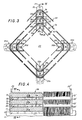
- FIGS. 3 and 4 A second mode of use is illustrated in FIGS. 3 and 4.
- Four wedges 31a, 31b, 31c, 31 are arranged in a corner on the edges 30a, 30b, 30c, 30d of a magnetic core 29.
- we will also do the same for the winding of a layer 36 thanks to the embedding of the shims 35a, 35b, 35c, 35d on the shims 33a, 33b, 33c, 33d.
- the shims 31 a to 31 d, 33a to 33d, 35a to 35d are immobilized radially by the winding tension of the layers 32, 34, 36.
- the various winding layers obtained are separated by ventilation channels 40, 41 and 42, thus making it possible to raise the current density in the winding wire compared to that possible in a conventional winding. where the various layers are glued to each other.
- the shims cooperate with each other in such a way that they cannot slide over each other, thus fixing, once and for all, the winding layers in the desired position, without risk. to see, subsequently, these layers accidentally slide relative to each other, thus destroying the winding.
- the wedge described in support of FIGS. 1 to 4, has been shown with a notch 15 in the shape of a right isosceles triangle thus allowing the adaptation of the wedge wedge on a core with rectangular section.
- the shape of the notch 15 can be modified to allow the adaptation of the shim on the edges of cores whose planes form an angle other than 90 °.
- the blanks 17, 17 'of the body cooperate with a median web 14 and partitions 16, 16', thus making it possible to produce a partially hollowed-out body.
- the invention cannot be limited to the arrangement shown, a partially hollowed-out body which can be obtained by other means known to those skilled in the art.
- the shape of the retainers 20, 20 ′, indented at 21, 21 ′ has of course been determined as a function of the arrangement of the median web 14 and the blanks 17, 17 ′. If this arrangement was modified, the shape of the retentions 20, 20 ' would consequently be so as to allow the cooperation described in support of FIGS. 3 and 4.
Landscapes
- Engineering & Computer Science (AREA)
- Power Engineering (AREA)
- Insulating Of Coils (AREA)
- Magnetically Actuated Valves (AREA)
- Control Of Motors That Do Not Use Commutators (AREA)
- Packaging Of Annular Or Rod-Shaped Articles, Wearing Apparel, Cassettes, Or The Like (AREA)
- Insulation, Fastening Of Motor, Generator Windings (AREA)
- Golf Clubs (AREA)
- Magnetic Resonance Imaging Apparatus (AREA)
- Coils Or Transformers For Communication (AREA)
Description
- La présente invention concerne une cale de bobinage pour bobinage d'un fil de bobinage sur un noyau magnétique.
- De telles cales sont généralement du genre comportant un corps allongé adapté à être placé en coin sur chaque angle d'un noyau pour permettre le bobinage direct d'un fil sur ce dernier. Ces cales connues ont le désavantage d'être lourdes et onéreuses.
- Aussi, un premier objet de la présente invention est de proposer une cale, exempte de ces inconvénients.
- Un second objet de la présente invention est de proposer une cale permettant la séparation de diverses couches de bobinage ou de divers enroulements sur un même noyau.
- En effet, selon les techniques usuelles, les divers enroulements d'un transformateur ou d'une inductance sont en général bobinés les uns sur les autres sur un corps de bobine.
- L'emploi de ces techniques de bobinage limite la densité de courant admissible dans les enroulements à cause de la mauvaise qualité de dissipation thermique propre à ce type de bobinage.
- Dans le but d'améliorer la dissipation, il a été proposé de séparer les couches de bobinage ou les enroulements et de laisser un canal de ventilation entre ceux-ci.
- Il existe déjà des dispositifs permettant une telle séparation. En général, ils comportent une cage de bobinage composée d'une armature pouvant être emboîtée sur un noyau magnétique de dimensions appropriées et autour de laquelle un premier enroulement peut être bobiné.
- La cage comporte en divers points de ses arêtes, des glissières en saillie vers l'extérieur, dans lesquelles peuvent être glissées des baguettes de coin. Ces baguettes, disposées entre chaque couche, permettent ainsi de laisser un canal de ventilation entre celles-ci.
- Cette technique n'est pas applicable pour un bobinage direct sur un noyau magnétique, car dans ce cas, on cherche justement à se passer d'un corps ou d'une cage de bobinage. De plus, l'emploi de cette technique implique la réalisation d'une cage pour chaque type de noyau, ce qui la rend en conséquence relativement onéreuse.
- L'invention propose dans ces perspectives, une cale du genre considéré, caractérisée par la combinaison d'au moins deux éléments de retenue en saillie radiale avec des évidements adaptés à s'emboîter sur les éléments de retenue d'une cale sous-jacente.
- Tout en allégeant le corps de la cale, cette disposition permet un bobinage direct sur un noyau magnétique, plusieurs canaux de ventilation pouvant être ménagés entre les diverses couches du bobinage, sans corps de bobines ni cages de bobinage.
- Les caractéristiques et avantages de la présente invention ressortiront d'ailleurs de la description qui va suivre, en référence aux dessins annexés sur lesquels:
- - la fig. 1 est une vue de côté et en coupe suivant la ligne I-I de la fig. 2 d'une cale selon la présente invention;
- - la fig. 2 est une vue en élévation et en coupe partielle de la cale suivant la ligne II-II de la fig. 1;
- - les fig. 3 et 4 sont des vues en coupe partielle, transversale et longitudinale illustrant l'utilisation de cales selon la présente invention.
- Suivant la forme de réalisation choisie et représentée aux fig. 1 à 4, une cale 10 est formée d'un corps allongé présentant des évidements 11 délimités par des flans 17, 17' et fermé aux extrémités par deux parois terminales 12,12'.
- Un voile médian 14 est disposé entre les parois 12, 12' à l'intérieur du corps, en sorte que ledit corps est divisé, dans le sens de la longueur, en deux parties symétriques, les évidements 11 s'étendant de part et d'autre dudit voile médian. Le voile 14 est échancré en 15 dans son épaisseur, et l'échancrure 15 est en forme de triangle isocèle rectangle.
- Les évidements 11 sont délimités par une pluralité de cloisons transversales 16, 16' disposées à l'intérieur du corps entre le voile 14 et chacun des flans 17,17', à intervalles réguliers.
- Les bords 24, 24' inférieurs des cloisons 16, 16' coopèrent avec l'échancrure 15 en sorte que les bords 24, 24' et l'échancrure 15 forment un triangle isocèle rectangle dont la base est comprise entre les arêtes 25, 25' des flans 17, 17'. Le corps est ainsi adapté à être placé en coin sur une arête, tout en étant en partie évidé.
- Suivant la forme de réalisation représentée, chaque extrémité du corps est munie d'un élément de retenue 20, 20', en saillie radiale, en forme de joues, ces joues étant échancrées en leur milieu en 21, 21'. Les échancrures 21, 21' sont rectangulaires. Les retenues 20, 20' sont décalées par rapport aux extrémités du corps, en sorte que les faces externes 22, 22' des retenues 20, 20' se trouvent sensiblement à l'aplomb des faces internes 13,13' des parois 12,12'.
- Sur les fig. 3 et 4, il apparaît que la cale est remarquable par la combinaison des éléments saillants de retenue 20, 20', avec les évidements 11, adjacents aux parois 12, 12', qui sont adaptés à s'emboîter sur les éléments de retenue 20, 20' d'une cale sous-jacente, les éléments saillants de retenue 20, 20' présentant la forme de joue d'un profil complémentaire à celui des évidements 11, avec une échancrure 21,21 ' d'emboîtement sur le voile médian 14 de la cale sous-jacente (voir par exemple l'encastrement de la cale 33a sur la cale 31 a).
- Suivant un premier mode d'utilisation de la cale décrite et représentée, une cale est disposée en coin sur chaque arête d'un noyau magnétique. On bobine alors directement le fil de bobinage autour du noyau muni des cales.
- Les retenues 20,20', en forme de joues, empêchent le fil de bobinage de glisser, ceci évitant d'avoir à attacher les dernières spires de chaque couche, ce qui permet de gagner du temps de bobinage par rapport aux techniques de l'art antérieur.
- Un second mode d'utilisation est illustré aux fig. 3 et 4. Quatre cales 31a, 31b, 31c, 31 sont disposées en coin sur les arêtes 30a, 30b, 30c, 30d d'un noyau magnétique 29. On procède alors au bobinage d'une première couche 32. On encastre ensuite les cales 33a, 33b, 33c, 33d respectivement sur les cales 31 a, 31 b, 31 c, 31 d. On procède alors au bobinage d'une deuxième couche 34. Suivant l'exemple choisi et représenté, on va également procéder de même pour le bobinage d'une couche 36 grâce à l'encastrement des cales 35a, 35b, 35c, 35d sur les cales 33a, 33b, 33c, 33d.
- Les cales 31 a à 31 d, 33a à 33d, 35a à 35d sont immobilisées radialement par la tension de bobinage des couches 32, 34, 36.
- En fig. 3, on peut voir que le voile médian 14 des diverses cales 22 et 35 coopère avec les échancrures 21 des retenues 20 respectivement des cales 31 et 33, assurant leur immobilisation relative en rotation.
- En fig. 4, on peut voir également que les retenues 20 et 20' des cales 31 et 33 coopèrent avec les parois 12, 12' des cales 33 et 35, en sorte que les cales se trouvent immobilisées les unes par rapport aux autres en sens longitudinal.
- Ainsi, suivant l'invention, les diverses couches de bobinage obtenues sont séparées par des canaux d'aération 40, 41 et 42, permettant ainsi d'élever la densité de courant dans le fil de bobinage par rapport à celle possible dans un bobinage classique où les diverses couches sont collées les unes aux autres.
- De plus, suivant l'invention, les cales coopèrent les unes avec les autres de façon telle qu'elles ne peuvent glisser les unes sur les autres, fixant ainsi, une fois pour toutes, les couches de bobinage dans la position voulue, sans risque de voir, par la suite, ces couches glisser accidentellement les unes par rapport aux autres, détruisant ainsi le bobinage.
- Bien entendu, l'invention ne se limite pas aux formes de réalisation décrites et représentées, mais englobe toutes variantes d'exécution, sans sortir pour autant du cadre de la présente invention.
- En particulier, la cale, décrite à l'appui des fig. 1 à 4, a été représentée avec une échancrure 15 en forme de triangle isocèle rectangle permettant ainsi l'adaptation de la cale en coin sur un noyau à section rectangulaire.
- Il est bien évident que la forme de l'échancrure 15 peut être modifiée pour permettre l'adaptation de la cale sur des arêtes de noyaux dont les plans forment un angle autre que 90°.
- De plus, suivant la forme de réalisation représentée, les flans 17, 17' du corps coopèrent avec un voile médian 14 et des cloisons 16, 16', permettant ainsi de réalisier un corps partiellement évidé.
- L'invention ne saurait se limiter à la disposition représentée, un corps partiellement évidé pouvant être obtenu par d'autres moyens connus de l'homme de l'art.
- De même, la forme des retenues 20, 20', échancrées en 21, 21', a bien entendu été déterminée en fonction de l'agencement du voile médian 14 et des flans 17, 17'. Si cet agencement était modifié, la forme des retenues 20, 20' le serait par voie de conséquence, de façon à permettre la coopération décrite à l'appui des fig. 3 et 4.
Claims (5)
Priority Applications (1)
| Application Number | Priority Date | Filing Date | Title |
|---|---|---|---|
| AT82401349T ATE12851T1 (de) | 1981-07-20 | 1982-07-20 | Wickelstuetzleiste. |
Applications Claiming Priority (2)
| Application Number | Priority Date | Filing Date | Title |
|---|---|---|---|
| FR8114071 | 1981-07-20 | ||
| FR8114071A FR2509904B1 (fr) | 1981-07-20 | 1981-07-20 | Cale de bobinage |
Publications (2)
| Publication Number | Publication Date |
|---|---|
| EP0070783A1 EP0070783A1 (fr) | 1983-01-26 |
| EP0070783B1 true EP0070783B1 (fr) | 1985-04-17 |
Family
ID=9260663
Family Applications (1)
| Application Number | Title | Priority Date | Filing Date |
|---|---|---|---|
| EP82401349A Expired EP0070783B1 (fr) | 1981-07-20 | 1982-07-20 | Cale de bobinage |
Country Status (4)
| Country | Link |
|---|---|
| EP (1) | EP0070783B1 (fr) |
| AT (1) | ATE12851T1 (fr) |
| DE (1) | DE3263128D1 (fr) |
| FR (1) | FR2509904B1 (fr) |
Families Citing this family (5)
| Publication number | Priority date | Publication date | Assignee | Title |
|---|---|---|---|---|
| GB8309558D0 (en) * | 1983-04-08 | 1983-05-11 | Gen Electric Co Plc | Electrical windings |
| DE3701686A1 (de) * | 1987-01-22 | 1988-08-04 | Vacuumschmelze Gmbh | Ringkerntransformator mit mindestens zwei wicklungen |
| FR2633440B1 (fr) * | 1988-06-24 | 1990-10-12 | Optelec Applic Optique Electro | Dispositif a enroulement electrique torique isole |
| EP0563124B1 (fr) * | 1990-12-20 | 1995-03-29 | Eastman Chemical Company | Procede en continu pour la preparation d'anhydride acetique ou de melanges d'anhydride acetique et d'acide acetique |
| EP2711943B1 (fr) * | 2012-09-22 | 2014-11-26 | ABB Technology AG | Listel d'angle à canal pour transformateurs ou bobines |
Family Cites Families (6)
| Publication number | Priority date | Publication date | Assignee | Title |
|---|---|---|---|---|
| US1853148A (en) * | 1931-08-21 | 1932-04-12 | Rigante Giuseppe | Coil structure |
| DE938496C (de) * | 1949-04-23 | 1956-02-02 | Brown | Spulendistanzierung fuer die Wicklungen von Transformatoren, elektrischen Maschinen und Apparaten |
| GB776692A (en) * | 1954-03-29 | 1957-06-12 | Smit & Willem & Co Nv | Improvements in and relating to transformer windings |
| US3289031A (en) * | 1963-01-28 | 1966-11-29 | Varian Associates | High frequency electron discharge devices and slow wave structures therefor |
| GB1213365A (en) * | 1968-11-08 | 1970-11-25 | B S & W Whiteley Ltd | Transformer insulation construction |
| DD101053A1 (de) * | 1972-12-21 | 1973-10-12 | Joachim Schmidt | Anordnung zur distanzierung der radialen kuehlkanaele bei roehrenwicklungen aus scheibenspulen |
-
1981
- 1981-07-20 FR FR8114071A patent/FR2509904B1/fr not_active Expired
-
1982
- 1982-07-20 EP EP82401349A patent/EP0070783B1/fr not_active Expired
- 1982-07-20 AT AT82401349T patent/ATE12851T1/de not_active IP Right Cessation
- 1982-07-20 DE DE8282401349T patent/DE3263128D1/de not_active Expired
Also Published As
| Publication number | Publication date |
|---|---|
| FR2509904A1 (fr) | 1983-01-21 |
| EP0070783A1 (fr) | 1983-01-26 |
| DE3263128D1 (de) | 1985-05-23 |
| ATE12851T1 (de) | 1985-05-15 |
| FR2509904B1 (fr) | 1985-12-27 |
Similar Documents
| Publication | Publication Date | Title |
|---|---|---|
| FR2617341A1 (fr) | Chemin de cables en treillis soude | |
| EP0070783A1 (fr) | Cale de bobinage | |
| CH363085A (fr) | Rotor à cage d'écureuil pour moteur à induction à entrefer annulaire plat | |
| FR3055696B1 (fr) | Platine support avec filtrage de vibrations d'un ventilateur, echangeur de chaleur, condenseur sur un element structurel du corps d'un appareil ou vehicule a moteur | |
| EP0860928A1 (fr) | Arbre de rotor d'une machine électrique | |
| CH643680A5 (fr) | Electro-aimant pour frein. | |
| BE864470A (fr) | Ensemble-support pour jeu de barres de transport d'energie electrique | |
| FR2775766A1 (fr) | Echangeur de chaleur a ailettes protegees, notamment pour vehicule automobile | |
| EP0479668B1 (fr) | Réglette de repères, notamment pour matériel électrique. | |
| BE1005840A3 (fr) | Electro-aimant a aimant permanent tenu par cage. | |
| EP0043744B1 (fr) | Bobine d'allumage pour moteur à combustion interne | |
| FR2742586A1 (fr) | Repartiteur | |
| EP0231135B1 (fr) | Perfectionnements aux caisses palettes | |
| FR3081984A1 (fr) | Boite collectrice et echangeur thermique correspondant | |
| FR2476374A1 (fr) | Lamelles de noyaux magnetiques, en particulier pour transformateurs | |
| EP0068925B1 (fr) | Borne de connexion, notamment pour transformateur | |
| FR2585462A1 (fr) | Echangeur de chaleur, et notamment radiateur ventile pour moteurs a combustion interne | |
| EP3899406B1 (fr) | Échangeur de chaleur avec joue d'extrémité brasée | |
| FR3154885A1 (fr) | Appareil à courant de Foucault | |
| FR2607332A1 (fr) | Moteur lineaire pour vehicules, en particulier ferroviaires, avec un induit en gouttiere etendue suivant le trajet du vehicule | |
| EP0269486B1 (fr) | Elément de structure suspendue comportant des cellules ouvertes situées dans un plan distinct | |
| FR2497598A2 (fr) | Procede et dispositif pour l'assemblage par collage d'un circuit magnetique et appareillage electrique comportant un tel circuit, en particulier transformateur | |
| CH160863A (fr) | Inducteur pour machine magnéto-électrique. | |
| BE710421A (fr) | ||
| BE1001586A6 (fr) | Element pour la fixation d'un rail sur une traverse de chemin de fer en beton. |
Legal Events
| Date | Code | Title | Description |
|---|---|---|---|
| PUAI | Public reference made under article 153(3) epc to a published international application that has entered the european phase |
Free format text: ORIGINAL CODE: 0009012 |
|
| AK | Designated contracting states |
Designated state(s): AT BE CH DE GB IT LI LU NL SE |
|
| 17P | Request for examination filed |
Effective date: 19830428 |
|
| RAP1 | Party data changed (applicant data changed or rights of an application transferred) |
Owner name: LEGRAND |
|
| ITF | It: translation for a ep patent filed | ||
| GRAA | (expected) grant |
Free format text: ORIGINAL CODE: 0009210 |
|
| AK | Designated contracting states |
Designated state(s): AT BE CH DE GB IT LI LU NL SE |
|
| REF | Corresponds to: |
Ref document number: 12851 Country of ref document: AT Date of ref document: 19850515 Kind code of ref document: T |
|
| REF | Corresponds to: |
Ref document number: 3263128 Country of ref document: DE Date of ref document: 19850523 |
|
| PG25 | Lapsed in a contracting state [announced via postgrant information from national office to epo] |
Ref country code: LU Free format text: LAPSE BECAUSE OF NON-PAYMENT OF DUE FEES Effective date: 19850731 |
|
| PLBE | No opposition filed within time limit |
Free format text: ORIGINAL CODE: 0009261 |
|
| STAA | Information on the status of an ep patent application or granted ep patent |
Free format text: STATUS: NO OPPOSITION FILED WITHIN TIME LIMIT |
|
| 26N | No opposition filed | ||
| PGFP | Annual fee paid to national office [announced via postgrant information from national office to epo] |
Ref country code: AT Payment date: 19900620 Year of fee payment: 9 |
|
| PGFP | Annual fee paid to national office [announced via postgrant information from national office to epo] |
Ref country code: LU Payment date: 19900711 Year of fee payment: 9 |
|
| PGFP | Annual fee paid to national office [announced via postgrant information from national office to epo] |
Ref country code: GB Payment date: 19900716 Year of fee payment: 9 |
|
| PGFP | Annual fee paid to national office [announced via postgrant information from national office to epo] |
Ref country code: CH Payment date: 19900723 Year of fee payment: 9 |
|
| PGFP | Annual fee paid to national office [announced via postgrant information from national office to epo] |
Ref country code: SE Payment date: 19900727 Year of fee payment: 9 Ref country code: DE Payment date: 19900727 Year of fee payment: 9 |
|
| ITTA | It: last paid annual fee | ||
| PGFP | Annual fee paid to national office [announced via postgrant information from national office to epo] |
Ref country code: NL Payment date: 19900731 Year of fee payment: 9 |
|
| PGFP | Annual fee paid to national office [announced via postgrant information from national office to epo] |
Ref country code: BE Payment date: 19900809 Year of fee payment: 9 |
|
| PG25 | Lapsed in a contracting state [announced via postgrant information from national office to epo] |
Ref country code: GB Effective date: 19910720 Ref country code: AT Effective date: 19910720 |
|
| PG25 | Lapsed in a contracting state [announced via postgrant information from national office to epo] |
Ref country code: SE Effective date: 19910721 |
|
| PG25 | Lapsed in a contracting state [announced via postgrant information from national office to epo] |
Ref country code: LI Effective date: 19910731 Ref country code: CH Effective date: 19910731 Ref country code: BE Effective date: 19910731 |
|
| BERE | Be: lapsed |
Owner name: LEGRAND Effective date: 19910731 |
|
| PG25 | Lapsed in a contracting state [announced via postgrant information from national office to epo] |
Ref country code: NL Effective date: 19920201 |
|
| NLV4 | Nl: lapsed or anulled due to non-payment of the annual fee | ||
| GBPC | Gb: european patent ceased through non-payment of renewal fee | ||
| REG | Reference to a national code |
Ref country code: CH Ref legal event code: PL |
|
| PG25 | Lapsed in a contracting state [announced via postgrant information from national office to epo] |
Ref country code: DE Effective date: 19920401 |
|
| EUG | Se: european patent has lapsed |
Ref document number: 82401349.4 Effective date: 19920210 |