EP0070759B1 - Procédé d'implantation de picots sur un mandrin et machine pour la mise en oeuvre de ce procédé - Google Patents
Procédé d'implantation de picots sur un mandrin et machine pour la mise en oeuvre de ce procédé Download PDFInfo
- Publication number
- EP0070759B1 EP0070759B1 EP82401269A EP82401269A EP0070759B1 EP 0070759 B1 EP0070759 B1 EP 0070759B1 EP 82401269 A EP82401269 A EP 82401269A EP 82401269 A EP82401269 A EP 82401269A EP 0070759 B1 EP0070759 B1 EP 0070759B1
- Authority
- EP
- European Patent Office
- Prior art keywords
- pins
- cylinder
- pin
- mandrel
- working head
- Prior art date
- Legal status (The legal status is an assumption and is not a legal conclusion. Google has not performed a legal analysis and makes no representation as to the accuracy of the status listed.)
- Expired
Links
- 238000000034 method Methods 0.000 title claims description 20
- 239000007943 implant Substances 0.000 title description 9
- 238000002513 implantation Methods 0.000 claims description 37
- 239000000463 material Substances 0.000 claims description 14
- 238000006073 displacement reaction Methods 0.000 claims description 9
- 239000006260 foam Substances 0.000 description 12
- 238000004519 manufacturing process Methods 0.000 description 9
- 238000004804 winding Methods 0.000 description 6
- KWGRBVOPPLSCSI-WPRPVWTQSA-N (-)-ephedrine Chemical compound CN[C@@H](C)[C@H](O)C1=CC=CC=C1 KWGRBVOPPLSCSI-WPRPVWTQSA-N 0.000 description 4
- 238000003780 insertion Methods 0.000 description 3
- 230000037431 insertion Effects 0.000 description 3
- 239000002184 metal Substances 0.000 description 3
- 238000005553 drilling Methods 0.000 description 2
- 238000012216 screening Methods 0.000 description 2
- 229920005830 Polyurethane Foam Polymers 0.000 description 1
- 206010000496 acne Diseases 0.000 description 1
- 238000013459 approach Methods 0.000 description 1
- 230000001609 comparable effect Effects 0.000 description 1
- 230000007547 defect Effects 0.000 description 1
- 230000001419 dependent effect Effects 0.000 description 1
- 238000013461 design Methods 0.000 description 1
- 230000000694 effects Effects 0.000 description 1
- 238000009434 installation Methods 0.000 description 1
- 238000012423 maintenance Methods 0.000 description 1
- 238000005457 optimization Methods 0.000 description 1
- 239000002245 particle Substances 0.000 description 1
- ISWSIDIOOBJBQZ-UHFFFAOYSA-N phenol group Chemical group C1(=CC=CC=C1)O ISWSIDIOOBJBQZ-UHFFFAOYSA-N 0.000 description 1
- 239000011496 polyurethane foam Substances 0.000 description 1
- 238000004080 punching Methods 0.000 description 1
- 239000011347 resin Substances 0.000 description 1
- 229920005989 resin Polymers 0.000 description 1
- 238000010079 rubber tapping Methods 0.000 description 1
- 230000035939 shock Effects 0.000 description 1
- 239000007787 solid Substances 0.000 description 1
- 229920001187 thermosetting polymer Polymers 0.000 description 1
- 238000013519 translation Methods 0.000 description 1
- 238000009941 weaving Methods 0.000 description 1
Images


Classifications
-
- D—TEXTILES; PAPER
- D04—BRAIDING; LACE-MAKING; KNITTING; TRIMMINGS; NON-WOVEN FABRICS
- D04H—MAKING TEXTILE FABRICS, e.g. FROM FIBRES OR FILAMENTARY MATERIAL; FABRICS MADE BY SUCH PROCESSES OR APPARATUS, e.g. FELTS, NON-WOVEN FABRICS; COTTON-WOOL; WADDING ; NON-WOVEN FABRICS FROM STAPLE FIBRES, FILAMENTS OR YARNS, BONDED WITH AT LEAST ONE WEB-LIKE MATERIAL DURING THEIR CONSOLIDATION
- D04H3/00—Non-woven fabrics formed wholly or mainly of yarns or like filamentary material of substantial length
- D04H3/02—Non-woven fabrics formed wholly or mainly of yarns or like filamentary material of substantial length characterised by the method of forming fleeces or layers, e.g. reorientation of yarns or filaments
- D04H3/07—Non-woven fabrics formed wholly or mainly of yarns or like filamentary material of substantial length characterised by the method of forming fleeces or layers, e.g. reorientation of yarns or filaments otherwise than in a plane, e.g. in a tubular way
- D04H3/073—Hollow cylinder shaped
-
- A—HUMAN NECESSITIES
- A46—BRUSHWARE
- A46D—MANUFACTURE OF BRUSHES
- A46D3/00—Preparing, i.e. Manufacturing brush bodies
- A46D3/06—Machines for both drilling bodies and inserting bristles
-
- B—PERFORMING OPERATIONS; TRANSPORTING
- B29—WORKING OF PLASTICS; WORKING OF SUBSTANCES IN A PLASTIC STATE IN GENERAL
- B29C—SHAPING OR JOINING OF PLASTICS; SHAPING OF MATERIAL IN A PLASTIC STATE, NOT OTHERWISE PROVIDED FOR; AFTER-TREATMENT OF THE SHAPED PRODUCTS, e.g. REPAIRING
- B29C33/00—Moulds or cores; Details thereof or accessories therefor
- B29C33/56—Coatings, e.g. enameled or galvanised; Releasing, lubricating or separating agents
-
- B—PERFORMING OPERATIONS; TRANSPORTING
- B29—WORKING OF PLASTICS; WORKING OF SUBSTANCES IN A PLASTIC STATE IN GENERAL
- B29C—SHAPING OR JOINING OF PLASTICS; SHAPING OF MATERIAL IN A PLASTIC STATE, NOT OTHERWISE PROVIDED FOR; AFTER-TREATMENT OF THE SHAPED PRODUCTS, e.g. REPAIRING
- B29C33/00—Moulds or cores; Details thereof or accessories therefor
- B29C33/76—Cores
-
- B—PERFORMING OPERATIONS; TRANSPORTING
- B29—WORKING OF PLASTICS; WORKING OF SUBSTANCES IN A PLASTIC STATE IN GENERAL
- B29C—SHAPING OR JOINING OF PLASTICS; SHAPING OF MATERIAL IN A PLASTIC STATE, NOT OTHERWISE PROVIDED FOR; AFTER-TREATMENT OF THE SHAPED PRODUCTS, e.g. REPAIRING
- B29C70/00—Shaping composites, i.e. plastics material comprising reinforcements, fillers or preformed parts, e.g. inserts
- B29C70/04—Shaping composites, i.e. plastics material comprising reinforcements, fillers or preformed parts, e.g. inserts comprising reinforcements only, e.g. self-reinforcing plastics
- B29C70/06—Fibrous reinforcements only
- B29C70/10—Fibrous reinforcements only characterised by the structure of fibrous reinforcements, e.g. hollow fibres
- B29C70/16—Fibrous reinforcements only characterised by the structure of fibrous reinforcements, e.g. hollow fibres using fibres of substantial or continuous length
- B29C70/24—Fibrous reinforcements only characterised by the structure of fibrous reinforcements, e.g. hollow fibres using fibres of substantial or continuous length oriented in at least three directions forming a three dimensional structure
-
- B—PERFORMING OPERATIONS; TRANSPORTING
- B29—WORKING OF PLASTICS; WORKING OF SUBSTANCES IN A PLASTIC STATE IN GENERAL
- B29K—INDEXING SCHEME ASSOCIATED WITH SUBCLASSES B29B, B29C OR B29D, RELATING TO MOULDING MATERIALS OR TO MATERIALS FOR MOULDS, REINFORCEMENTS, FILLERS OR PREFORMED PARTS, e.g. INSERTS
- B29K2861/00—Use of condensation polymers of aldehydes or ketones or derivatives thereof, as mould material
- B29K2861/04—Phenoplasts
-
- B—PERFORMING OPERATIONS; TRANSPORTING
- B29—WORKING OF PLASTICS; WORKING OF SUBSTANCES IN A PLASTIC STATE IN GENERAL
- B29K—INDEXING SCHEME ASSOCIATED WITH SUBCLASSES B29B, B29C OR B29D, RELATING TO MOULDING MATERIALS OR TO MATERIALS FOR MOULDS, REINFORCEMENTS, FILLERS OR PREFORMED PARTS, e.g. INSERTS
- B29K2875/00—Use of PU, i.e. polyureas or polyurethanes or derivatives thereof, as mould material
-
- Y—GENERAL TAGGING OF NEW TECHNOLOGICAL DEVELOPMENTS; GENERAL TAGGING OF CROSS-SECTIONAL TECHNOLOGIES SPANNING OVER SEVERAL SECTIONS OF THE IPC; TECHNICAL SUBJECTS COVERED BY FORMER USPC CROSS-REFERENCE ART COLLECTIONS [XRACs] AND DIGESTS
- Y10—TECHNICAL SUBJECTS COVERED BY FORMER USPC
- Y10T—TECHNICAL SUBJECTS COVERED BY FORMER US CLASSIFICATION
- Y10T29/00—Metal working
- Y10T29/49—Method of mechanical manufacture
- Y10T29/49826—Assembling or joining
- Y10T29/49828—Progressively advancing of work assembly station or assembled portion of work
-
- Y—GENERAL TAGGING OF NEW TECHNOLOGICAL DEVELOPMENTS; GENERAL TAGGING OF CROSS-SECTIONAL TECHNOLOGIES SPANNING OVER SEVERAL SECTIONS OF THE IPC; TECHNICAL SUBJECTS COVERED BY FORMER USPC CROSS-REFERENCE ART COLLECTIONS [XRACs] AND DIGESTS
- Y10—TECHNICAL SUBJECTS COVERED BY FORMER USPC
- Y10T—TECHNICAL SUBJECTS COVERED BY FORMER US CLASSIFICATION
- Y10T29/00—Metal working
- Y10T29/49—Method of mechanical manufacture
- Y10T29/49826—Assembling or joining
- Y10T29/49885—Assembling or joining with coating before or during assembling
-
- Y—GENERAL TAGGING OF NEW TECHNOLOGICAL DEVELOPMENTS; GENERAL TAGGING OF CROSS-SECTIONAL TECHNOLOGIES SPANNING OVER SEVERAL SECTIONS OF THE IPC; TECHNICAL SUBJECTS COVERED BY FORMER USPC CROSS-REFERENCE ART COLLECTIONS [XRACs] AND DIGESTS
- Y10—TECHNICAL SUBJECTS COVERED BY FORMER USPC
- Y10T—TECHNICAL SUBJECTS COVERED BY FORMER US CLASSIFICATION
- Y10T29/00—Metal working
- Y10T29/51—Plural diverse manufacturing apparatus including means for metal shaping or assembling
- Y10T29/5191—Assembly
-
- Y—GENERAL TAGGING OF NEW TECHNOLOGICAL DEVELOPMENTS; GENERAL TAGGING OF CROSS-SECTIONAL TECHNOLOGIES SPANNING OVER SEVERAL SECTIONS OF THE IPC; TECHNICAL SUBJECTS COVERED BY FORMER USPC CROSS-REFERENCE ART COLLECTIONS [XRACs] AND DIGESTS
- Y10—TECHNICAL SUBJECTS COVERED BY FORMER USPC
- Y10T—TECHNICAL SUBJECTS COVERED BY FORMER US CLASSIFICATION
- Y10T29/00—Metal working
- Y10T29/53—Means to assemble or disassemble
- Y10T29/53313—Means to interrelatedly feed plural work parts from plural sources without manual intervention
- Y10T29/53383—Means to interrelatedly feed plural work parts from plural sources without manual intervention and means to fasten work parts together
- Y10T29/53396—Means to interrelatedly feed plural work parts from plural sources without manual intervention and means to fasten work parts together by friction fit
-
- Y—GENERAL TAGGING OF NEW TECHNOLOGICAL DEVELOPMENTS; GENERAL TAGGING OF CROSS-SECTIONAL TECHNOLOGIES SPANNING OVER SEVERAL SECTIONS OF THE IPC; TECHNICAL SUBJECTS COVERED BY FORMER USPC CROSS-REFERENCE ART COLLECTIONS [XRACs] AND DIGESTS
- Y10—TECHNICAL SUBJECTS COVERED BY FORMER USPC
- Y10T—TECHNICAL SUBJECTS COVERED BY FORMER US CLASSIFICATION
- Y10T29/00—Metal working
- Y10T29/53—Means to assemble or disassemble
- Y10T29/53478—Means to assemble or disassemble with magazine supply
-
- Y—GENERAL TAGGING OF NEW TECHNOLOGICAL DEVELOPMENTS; GENERAL TAGGING OF CROSS-SECTIONAL TECHNOLOGIES SPANNING OVER SEVERAL SECTIONS OF THE IPC; TECHNICAL SUBJECTS COVERED BY FORMER USPC CROSS-REFERENCE ART COLLECTIONS [XRACs] AND DIGESTS
- Y10—TECHNICAL SUBJECTS COVERED BY FORMER USPC
- Y10T—TECHNICAL SUBJECTS COVERED BY FORMER US CLASSIFICATION
- Y10T29/00—Metal working
- Y10T29/53—Means to assemble or disassemble
- Y10T29/53657—Means to assemble or disassemble to apply or remove a resilient article [e.g., tube, sleeve, etc.]
Definitions
- the present invention relates to a method of implanting pins on a support mandrel made of a material capable of receiving the pins by direct implantation by pressure, to form rows of pins aligned along generatrices of the mandrel, as well as a machine for the implementation of this process.
- the straightness quality of the spike must be all the more perfect the greater the distance between the surface of the foam and the guide members.
- the pins generally obtained from prepolymerized fibrous elements, exhibit a slight annoying arrow as soon as we approach lengths of 50 mm and more.
- the implantation with such pins present at the level of the mannequin makes in the foam of strong irregularities. To overcome this defect, it is necessary to guide the pin in a very complete manner and to design sufficiently developed guide means so as not to hinder the rest of the manufacturing cycle.
- the present invention specifically relates to a method of implanting pins on a support mandrel making it possible to implant pins of great length (greater than 50 mm) with sufficient precision so as not to prevent the subsequent establishment of layers of wires superimposed in the corridors defined between the pins.
- the invention also relates to a machine for implementing this method.
- this compact support having to withstand high winding pressures as well as certain thermal shocks later on, it has been studied and implemented in two phases.
- a preferably two-layer mandrel consisting of a metal ring is made in which, for example, foam has been expanded.
- at least a pre-hole is made in the metal layer.
- the perforations are preferably made to a depth at least equal to the length of the portion of the pins to be implanted in the mandrel, the diameter of the perforations being substantially equal to that of the pimples.
- the invention also relates to a machine for implanting pins on a support mandrel made of a material capable of receiving the pins by direct implantation by pressure, to form rows of pins aligned along generatrices of the mandrel, this machine comprising means for supporting the mandrel in a rotary manner, means for rotating the mandrel step by step about its axis, a working head carrying means for implanting the pins in the mandrel and means for effecting a given relative displacement, parallel to the generator of the nearest mandrel, between the working head and the mandrel, and being characterized in that the working head also carries a punch arranged in the same row as the stud to be implanted and offset by at least once the pitch defined by two successive pins of the same row and towards the front relative to this pin, in the direction of movement of the working head, the means for implanting the pins acting simultaneously on the punch to make a preliminary perforation of the mandrel.
- the guide head comprises a guide piece which is flush with the external surface of the mandrel and comprising a first guide hole in which the punch is received and a second guide hole in which is received the pin to be implanted, the wall of the second guide hole being formed on a movable door at the rear of the guide head in the direction of rotation of the mandrel, suitable control means opening said door after implantation of a pin, to allow rotation of the latter with the mandrel, and closing said door after this rotation.
- the means for implanting the pins comprise a first movable part in a direction parallel to the guide holes formed in the guide part and placed above the latter, the first part coming to bear on the during its movement on a second part supporting the punch, and carrying an implantation rod coming to bear on the pin to be implanted.
- a spike holder barrel provided with regularly spaced housings capable of receiving the spikes, can then be placed between the first movable part and the guide piece, this barrel being supplied with spikes by a vertical feed tube integral with the first piece and means being provided for rotating the barrel by a given angle corresponding to the space separating two housings each time a pin has been implanted in the mandrel.
- the machine according to the invention comprises a table 10, substantially horizontal, above which is likely to move a plate 12, also horizontal. More specifically, the plate 12 is guided by two parallel posts 14 carried by the table 10. In addition, the plate 12 can move along these posts as a result of the cooperation of an endless screw 16, also horizontal and parallel to the balusters 14, with an appropriate tapping formed in a nut 18 secured to the plate 12.
- the worm 16 is rotated through a reduction gear 20 by a stepping motor 22 fixed on the table 10.
- the plate 12 carries at each of its ends an arm 24 which projects upwards and rotatably supports a horizontal shaft 26, the axis of which is also parallel to those of the balusters 14 and of the worm 16.
- the shaft 26 is integral with a pinion 28 which meshes with an endless screw 30 whose rotation is controlled by a stepping motor 32 through a reduction gear 34.
- the motor 32 is fixed to the plate 12.
- the shaft 26 also supports, between the arms 24, a support mandrel 36 on which, according to the invention, it is necessary to implant rigid pins.
- a support mandrel 36 on which, according to the invention, it is necessary to implant rigid pins.
- the external shape of the mandrel 36 defines the internal envelope of the body of revolution to be produced.
- this mandrel is cylindrical and therefore makes it possible to manufacture a body of revolution having a cylindrical recess.
- the mandrel 36 is produced by means of a material which is sufficiently rigid to be able to support the pins and sufficiently flexible to allow the implantation of the latter without requiring too great a force.
- the mandrel is produced by means of a rigid foam of the kind known in the art under the terms of phenolic foam or polyurethane foam.
- the mandrel can be made of foam in its entirety or be constituted by an outer layer of a hard material, in particular metallic, which is filled with foam. In the latter case, which makes it possible to give the mandrel good mechanical strength, it is necessary to make preliminary perforations passing through at least the outer layer.
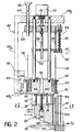
- the implantation of the pins and, in accordance with the invention, the production of preliminary perforations 112 are carried out by means of a working head 40 mounted on the vertical branch of a bracket 50 by means of adjustment screws 46
- the horizontal branch of the bracket 50 is itself mounted on a vertical support 42 by means of adjustment screws 44.
- the support 42 is fixed to the table 10.
- the working head 40 can thus be positioned vertically above the mandrel 36 as illustrated in FIG. 1 by acting on screws 44 and 46.
- the working head 40 comprises a U-shaped support piece 48, the intermediate branch 48a is vertical and fixed by the screws 46 to the square 50 and the upper horizontal end branches 48b and lower 48c support between them vertical guide columns 52.
- the lower branch 48c forms at its upper part a vertical shaft around which is received a rotating barrel 54 equipped as illustrated in particular in FIG. 4 of a number of vertical holes or housings 56, distributed regularly over its circumference.
- the rotation step by step of the barrel 54 is controlled by a jack 58 fixed to the support 48 and alternately moving from top to bottom and from bottom to top a part 60 provided with appropriate cam surfaces which cooperate with radial rods 62 carried by the barrel 54, so as to rotate the latter by a value corresponding to the pitch separating two adjacent holes 56 during the operation of the motor 58.
- the holes 56 receive the pins 38 by a vertical supply tube 64 which ends at its upper end by a funnel 66 into which the pins are introduced by any known means.
- the supply tube 64 is fixed to a part constituted by a horizontal plate 68 able to move along the columns 52. More specifically, the plate 68 is fixed to the lower end of the rod 70 of a pneumatic cylinder 72 supported by the upper branch 48b of the part 48. In the extension of the rod 70, the plate 68 carries a vertical finger 74 which projects downwards over a length sufficient to pass through a hole 76 formed in the lower branch 48c when the plate 68 is in the lower position, as will be seen later.
- the plate 68 also carries a vertical implantation punch or rod 78, which also projects downwards and which is arranged opposite one of the pins 38 carried by the barrel 54.
- the rod 78 is arranged in face of a pin 38 which is itself disposed in front of a hole 80 in the lower branch 48c of the part 48.
- the rod 78 is guided, the diameter of which is practically equal to that of the pins, by means of an intermediate horizontal plate 82 fixed on a vertical screw 84 passing through the plate 68 and urged downwards away from the latter by a spring 86.
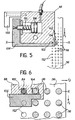
- a guide piece 88 which preferably comes flush with the external surface of the mandrel 36, as shown in FIG. 2.
- the part 88 has below the lower branch 48c a recess 90 in which is received a movable part constituted by a horizontal plate 92 supporting a punch 94.
- the guiding of the plate 92 is carried out by means of vertical columns 96 fixed between room 88 and branch 48c.
- a screw 98 projects downwards from the plate 92 through the part 88.
- a spring 100 mounted on the screw 98 between the part 88 and the plate 92 biases the latter upwards in the position shown in fig. 2.
- the punch 94 is fixed to the plate 92 and passes through a first vertical guide hole 102 formed in the guide piece 88. More precisely, when the plate 92 is in the high position, the end of the punch 94 is flush with the lower end of the part 88.
- the latter also has a second vertical guide hole 104 aligned with the hole 80 for supplying pins 38, so as to ensure effective guidance of the latter during their implantation.
- the working head 40 is arranged so that the axes of the guide holes 102 and 104 are placed in the vertical plane passing through the axis XX of the mandrel 36.
- the axes of the holes 102 and 104 are offset one relative to the other by a distance corresponding to an integer number of times the distance or the pitch separating two successive pins of the same longitudinal row on the mandrel, the guide hole 102 of the punch 94 being placed in front relative to the guide hole 104 of the pins relative to the direction of implantation of the latter. In the embodiment shown, this distance is equal to once the pitch defined by the pins 38 of the same longitudinal row.
- the guide of the pin which has just been implanted according to the guide 104 must be interrupted momentarily when the rotation of the mandrel occurs.
- the guide hole 104 of the pins to be implanted is formed at the rear end of the guide piece 88 relative to the direction of rotation of the mandrel shown diagrammatically by the arrow F 1 in the figures.
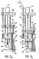
- the rear edge of the hole 104 is formed on a sliding door 106 which opens just before the rotation of the mandrel in the direction of the arrow F l . As shown in particular in fig.
- the door 106 moves parallel to the axis of the mandrel under the action of a pneumatic cylinder 108 carried by the guide piece 88, a spring 110 acting normally between the piece 88 and the door 106 to maintain the latter in closed position.
- the stroke of the door 106 is limited by a stop 150 fixed to the part 88.
- the entire surface of the mandrel 36 passes under the working head 40 by the step-by-step movements combined in rotation and in translation which are transmitted to the mandrel by the motors 32 and 22. Between each of these movements, the working head 40 is used to carry out two operations simultaneously in accordance with the present invention.
- the first of these operations consists of a prior perforation of the mandrel by means of the punch 94, while the second operation consists of implanting a pin 38 in the perforation carried out in the preceding round by the punch when the distance separating the holes 102 and 104 is equal at the distance separating two consecutive pins of the same row.
- the implementation of the working head 40 results first of all in the descent of the plate 68 under the action of the jack 72. Firstly and as illustrated in FIG. 3a, this descent allows the rod 78 carried by the plate 68 to push the pin 38 opposite in the hole 80 formed in the branch 48c, then in the guide hole 104 of the part 88. During this first phase of the movement, the end of the rod 78 acting on the pin is guided by the plate 82. When the latter abuts against the barrel 54, the latter itself guides the rod 78 and the spring 86 is compressed as illustrated in FIG. 3b. When this spring is fully compressed, the corresponding pin is pressed into the opposite perforation 112 previously made in the mandrel. It should be noted that, during this implantation, the pin is perfectly guided and positioned by the hole 104 formed in the guide part 88.
- the rod 74 passes through the hole 76 and bears by its lower end against the plate 92. It thus biases the latter down against the spring 100.
- This displacement of the plate 92 has the effect of projecting the punch 94 of the part 88 and to push it into the mandrel 36.
- a perforation 112 is thus produced in the mandrel.
- the diameter of this perforation is substantially equal to the diameter of the pin to be implanted and its depth is slightly greater than the length of the part of the pins which must be implanted in the mandrel.
- this prior perforation subsequently ensures a very precise positioning and guidance of the pins 38.
- the simultaneous production of the preliminary perforations 112 and the actual implantation of the pins 38 in these perforations by means of a single working head 40 makes it possible to carry out the preliminary perforations exactly where the pins are to be installed later. It is thus possible to implant pins of great length without the subsequent operations of winding and screening of the mandrel being made impractical.
- the descent of the plate 68 brings the lower end of the tube 64 close to the barrel, which makes it possible to easily introduce a pin 38 into the corresponding hole 66 by causing a pin to drop by the tube 64 at this time as schematically illustrated in fig. 3b.
- the timing of the supply of pins can be obtained by any known means controlled by an automation.
- the jack 72 rises all the members of the working head 40 to the standby position shown in FIG. 2.
- the rotation of the mandrel 36 in the direction of the arrow F 1 under the action of the motor 32 and, if necessary, its advance in the direction of the arrow F 2 (fig. 1, 2, 5 and 6) under the action of the motor 22 can then be controlled to bring the working head 40 to its next working position.
- these movements must be preceded by an opening of the door 106 under the action of the jack 108 so that the pin 38 which has just been implanted can be released from the guide hole 104.
- the implementations of the motors 22 and 32 are accompanied by an actuation of the jack 58 allowing via of the system 60 and of the fingers 62 of controlling the rotation of the barrel 54 in order to bring a pin 38 opposite the rod 78 and an empty hole 56 opposite the tube 64.
- the invention is not limited to the embodiment which has just been described by way of example, but covers all its variants.
- the implantation of the pins can preferably be done either by a helix, or by equidistant circles.
- the means allowing the punch to be actuated and the pin inserted can be different from the means described, without departing from the scope of the invention.
- the mandrel is not necessarily cylindrical, but can have any form of revolution.
- the displacement of the mandrel parallel to its axis under the action of the motor 22 can be accompanied by a displacement of the working head perpendicular to the generator of the nearest mandrel.
- the mandrel may also have a hard outer layer, previously perforated.
Landscapes
- Engineering & Computer Science (AREA)
- Mechanical Engineering (AREA)
- Textile Engineering (AREA)
- Chemical & Material Sciences (AREA)
- Composite Materials (AREA)
- Manufacturing & Machinery (AREA)
- Automatic Assembly (AREA)
- Perforating, Stamping-Out Or Severing By Means Other Than Cutting (AREA)
- Prostheses (AREA)
Applications Claiming Priority (2)
| Application Number | Priority Date | Filing Date | Title |
|---|---|---|---|
| FR8113868 | 1981-07-16 | ||
| FR8113868A FR2509706A1 (fr) | 1981-07-16 | 1981-07-16 | Procede d'implantation de picots sur un mandrin et machine pour la mise en oeuvre de ce procede |
Publications (2)
| Publication Number | Publication Date |
|---|---|
| EP0070759A1 EP0070759A1 (fr) | 1983-01-26 |
| EP0070759B1 true EP0070759B1 (fr) | 1985-02-06 |
Family
ID=9260557
Family Applications (1)
| Application Number | Title | Priority Date | Filing Date |
|---|---|---|---|
| EP82401269A Expired EP0070759B1 (fr) | 1981-07-16 | 1982-07-06 | Procédé d'implantation de picots sur un mandrin et machine pour la mise en oeuvre de ce procédé |
Country Status (6)
| Country | Link |
|---|---|
| US (2) | US4437221A (OSRAM) |
| EP (1) | EP0070759B1 (OSRAM) |
| JP (1) | JPS5834729A (OSRAM) |
| CA (1) | CA1190029A (OSRAM) |
| DE (1) | DE3262216D1 (OSRAM) |
| FR (1) | FR2509706A1 (OSRAM) |
Families Citing this family (15)
| Publication number | Priority date | Publication date | Assignee | Title |
|---|---|---|---|---|
| DE3325100A1 (de) * | 1983-07-12 | 1985-01-24 | Fa. Anton Zahoransky, 7868 Todtnau | Buerstenherstellungsmaschine |
| JPS6071132A (ja) * | 1983-09-29 | 1985-04-23 | Toyoda Gosei Co Ltd | ウェザ−ストリップの自動クリップ取付装置 |
| FR2574386B1 (fr) * | 1984-12-11 | 1986-12-26 | Commissariat Energie Atomique | Procede et dispositif d'implantation de joncs sur un mandrin |
| JPS61146435A (ja) * | 1984-12-21 | 1986-07-04 | Toyoda Gosei Co Ltd | クリツプ自動取付装置 |
| FR2580987B1 (fr) * | 1985-04-25 | 1987-07-24 | Europ Propulsion | Procede d'implantation d'elements rigides a la surface d'un corps et application a la fabrication de textures multidirectionnelles notamment pour materiaux composites |
| FR2587318B1 (fr) * | 1985-09-18 | 1987-10-30 | Commissariat Energie Atomique | Procede et machine pour la fabrication de pieces creuses de revolution formees de fils s'etendant selon trois directions differentes. |
| FR2592404B1 (fr) * | 1985-12-30 | 1989-06-09 | Pradom Ltd | Nouveaux materiaux composites fibre-matrice a fibres strictement positionnees et orientees et leur procede de preparation. |
| FR2612950B1 (fr) * | 1987-03-25 | 1989-06-09 | Aerospatiale | Procede de fabrication d'elements d'armature composites tisses en trois dimensions, machine pour sa mise en oeuvre et produit obtenu |
| US5291652A (en) * | 1987-10-13 | 1994-03-08 | Meurer Nonfood Product Gmbh | Apparatus for the production of a device for detaching portions of plate-like workpieces |
| ES2048182T3 (es) * | 1987-10-13 | 1994-03-16 | Meurer Nonfood Product Gmbh | Dispositivo y procedimiento para fabricar un dispositivo para la mecanizacion de piezas de trabajo en forma de placa o similares. |
| US4897904A (en) * | 1988-03-29 | 1990-02-06 | Joy Technologies, Inc. | Apparatus which provides for the placement of a bit point of a bit at a predetermined position |
| US4947535A (en) * | 1988-03-29 | 1990-08-14 | Joy Technologies, Inc. | Method which provides for the placement of a bit point of a bit at a predetermined position |
| USD425455S (en) * | 1999-07-28 | 2000-05-23 | Blake Vann | Stretcher |
| DE102007001361A1 (de) * | 2007-01-09 | 2008-07-10 | Robert Bosch Gmbh | Energieerzeugende Einrichtung für ein Reifensensormodul |
| CN115488605B (zh) * | 2022-09-29 | 2023-06-09 | 广东南奥交通设备有限公司 | 一种动车组模块化管路加工设备 |
Family Cites Families (10)
| Publication number | Priority date | Publication date | Assignee | Title |
|---|---|---|---|---|
| US2171388A (en) | 1936-12-23 | 1939-08-29 | Berger Ludwig | Method and means for binding fibrous building material |
| US2244073A (en) | 1938-10-25 | 1941-06-03 | Motor Wheel Corp | Method of riveting |
| US2972789A (en) | 1959-11-06 | 1961-02-28 | Gen Motors Corp | Sealing strip and method of manufacturing such strip |
| US3581378A (en) | 1969-03-03 | 1971-06-01 | Gillette Co | Method and apparatus for assembling a porous point pen |
| US3727294A (en) | 1972-03-20 | 1973-04-17 | Amp Inc | Method and machine for forming and inserting workpieces in an apertured workpiece holder |
| US3851370A (en) * | 1974-01-21 | 1974-12-03 | E Laturnau | Linear inserting apparatus for masonry building blocks |
| US3948616A (en) | 1974-07-24 | 1976-04-06 | Tangen Drives, Inc. | Apparatus for pin insertion and method |
| US3977062A (en) * | 1975-01-22 | 1976-08-31 | Knut Olof Lennart Wallman | Method of assembling blower rotors |
| US4062108A (en) * | 1976-07-02 | 1977-12-13 | Champion International Corporation | Stick insertion apparatus |
| FR2408676A1 (fr) * | 1977-09-23 | 1979-06-08 | Commissariat Energie Atomique | Procede et dispositif de fabrication de pieces ou corps en materiau tridimensionnel |
-
1981
- 1981-07-16 FR FR8113868A patent/FR2509706A1/fr active Granted
- 1981-12-02 US US06/326,755 patent/US4437221A/en not_active Expired - Lifetime
-
1982
- 1982-07-06 EP EP82401269A patent/EP0070759B1/fr not_active Expired
- 1982-07-06 DE DE8282401269T patent/DE3262216D1/de not_active Expired
- 1982-07-14 CA CA000407296A patent/CA1190029A/en not_active Expired
- 1982-07-15 JP JP57123755A patent/JPS5834729A/ja active Granted
-
1984
- 1984-03-09 US US06/587,977 patent/US4536930A/en not_active Expired - Lifetime
Also Published As
| Publication number | Publication date |
|---|---|
| FR2509706B1 (OSRAM) | 1983-11-04 |
| FR2509706A1 (fr) | 1983-01-21 |
| EP0070759A1 (fr) | 1983-01-26 |
| DE3262216D1 (en) | 1985-03-21 |
| JPS5834729A (ja) | 1983-03-01 |
| US4437221A (en) | 1984-03-20 |
| JPS6332577B2 (OSRAM) | 1988-06-30 |
| CA1190029A (en) | 1985-07-09 |
| US4536930A (en) | 1985-08-27 |
Similar Documents
| Publication | Publication Date | Title |
|---|---|---|
| EP0070759B1 (fr) | Procédé d'implantation de picots sur un mandrin et machine pour la mise en oeuvre de ce procédé | |
| CA2147040C (fr) | Procede et machine pour la realisation d'une armature pour une piece de matiere composite | |
| EP0284497B1 (fr) | Procédé de fabrication d'éléments d'armature composites tissés en trois dimensions, machine pour sa mise en oeuvre et produit obtenu | |
| FR2677802A1 (fr) | Bobinage electrique et son procede d'enroulement. | |
| EP0101351B1 (fr) | Procédé et machine de réalisation de pièces complexes par tissage multidirectionnel | |
| FR2587318A1 (fr) | Procede et machine pour la fabrication de pieces creuses de revolution formees de fils s'etendant selon trois directions differentes. | |
| EP0039264B1 (fr) | Procédé et machine pour la fabrication de pièces de révolution à partir de fils | |
| EP0090744B1 (fr) | Machine à scie annulaire pour le tronçonnage de tubes | |
| FR2492794A1 (fr) | Machine d'enroulement d'un fil en helice | |
| EP0098762B1 (fr) | Armatures creuses de révolution réalisées par tissage tridimensionnel, procédé et machine de fabrication de telles armatures | |
| EP0044760B1 (fr) | Procédé et machine pour la fabrication de pièces de révolution à partir de fils disposés selon trois directions | |
| FR2498979A1 (fr) | Procede de fabrication de longerons de pale d'helicoptere | |
| EP2589474A1 (fr) | Procédé automatisé d'insertion de corps d'isolation dans les alvéoles de blocs de construction, et ligne d'insertion automatique pour sa mise en oeuvre | |
| EP1694451A1 (fr) | Machine de fabrication en continu de treillis metallique soude | |
| EP0320357B1 (fr) | Machine pour l'enlèvement du fil espaceur des aiguilles de combustible nucléaire | |
| EP0536029B1 (fr) | Procédé et machine pour la réalisation d'armatures fibreuses creuses | |
| EP0187068B1 (fr) | Procédé et dispositif d'implantation de joncs sur un mandrin | |
| EP0380452B1 (fr) | Procédé et machine pour la formation de chaînes ornementales avec des mailles en hélice cylindrique | |
| EP0338909A1 (fr) | Procédé et dispositif d'alimentation automatique d'une machine à coudre | |
| BE557937A (OSRAM) | ||
| FR2581223A1 (fr) | Procede et installation pour l'encartouchage de piles de pieces de monnaie | |
| WO1987000505A1 (fr) | Machine pour la mise en place de fruits a l'interieur de bocaux de conservation | |
| BE425565A (OSRAM) | ||
| CH505670A (it) | Dispositivo di rilegatura de fogli |
Legal Events
| Date | Code | Title | Description |
|---|---|---|---|
| PUAI | Public reference made under article 153(3) epc to a published international application that has entered the european phase |
Free format text: ORIGINAL CODE: 0009012 |
|
| AK | Designated contracting states |
Designated state(s): BE CH DE GB IT LI NL SE |
|
| 17P | Request for examination filed |
Effective date: 19830606 |
|
| ITF | It: translation for a ep patent filed | ||
| GRAA | (expected) grant |
Free format text: ORIGINAL CODE: 0009210 |
|
| AK | Designated contracting states |
Designated state(s): BE CH DE GB IT LI NL SE |
|
| REF | Corresponds to: |
Ref document number: 3262216 Country of ref document: DE Date of ref document: 19850321 |
|
| PLBE | No opposition filed within time limit |
Free format text: ORIGINAL CODE: 0009261 |
|
| STAA | Information on the status of an ep patent application or granted ep patent |
Free format text: STATUS: NO OPPOSITION FILED WITHIN TIME LIMIT |
|
| 26N | No opposition filed | ||
| PGFP | Annual fee paid to national office [announced via postgrant information from national office to epo] |
Ref country code: BE Payment date: 19900629 Year of fee payment: 9 |
|
| PGFP | Annual fee paid to national office [announced via postgrant information from national office to epo] |
Ref country code: SE Payment date: 19900702 Year of fee payment: 9 |
|
| PGFP | Annual fee paid to national office [announced via postgrant information from national office to epo] |
Ref country code: CH Payment date: 19900711 Year of fee payment: 9 |
|
| ITTA | It: last paid annual fee | ||
| PGFP | Annual fee paid to national office [announced via postgrant information from national office to epo] |
Ref country code: NL Payment date: 19900731 Year of fee payment: 9 |
|
| PG25 | Lapsed in a contracting state [announced via postgrant information from national office to epo] |
Ref country code: SE Effective date: 19910707 |
|
| PG25 | Lapsed in a contracting state [announced via postgrant information from national office to epo] |
Ref country code: LI Effective date: 19910731 Ref country code: CH Effective date: 19910731 Ref country code: BE Effective date: 19910731 |
|
| BERE | Be: lapsed |
Owner name: COMMISSARIAT A L'ENERGIE ATOMIQUEETABLISSEMENT DE Effective date: 19910731 |
|
| PG25 | Lapsed in a contracting state [announced via postgrant information from national office to epo] |
Ref country code: NL Effective date: 19920201 |
|
| NLV4 | Nl: lapsed or anulled due to non-payment of the annual fee | ||
| REG | Reference to a national code |
Ref country code: CH Ref legal event code: PL |
|
| EUG | Se: european patent has lapsed |
Ref document number: 82401269.4 Effective date: 19920210 |
|
| PGFP | Annual fee paid to national office [announced via postgrant information from national office to epo] |
Ref country code: GB Payment date: 19950630 Year of fee payment: 14 |
|
| PGFP | Annual fee paid to national office [announced via postgrant information from national office to epo] |
Ref country code: DE Payment date: 19950710 Year of fee payment: 14 |
|
| PG25 | Lapsed in a contracting state [announced via postgrant information from national office to epo] |
Ref country code: GB Effective date: 19960706 |
|
| GBPC | Gb: european patent ceased through non-payment of renewal fee |
Effective date: 19960706 |
|
| PG25 | Lapsed in a contracting state [announced via postgrant information from national office to epo] |
Ref country code: DE Effective date: 19970402 |