EP0070377A2 - Broken thread suction device - Google Patents
Broken thread suction device Download PDFInfo
- Publication number
- EP0070377A2 EP0070377A2 EP82104694A EP82104694A EP0070377A2 EP 0070377 A2 EP0070377 A2 EP 0070377A2 EP 82104694 A EP82104694 A EP 82104694A EP 82104694 A EP82104694 A EP 82104694A EP 0070377 A2 EP0070377 A2 EP 0070377A2
- Authority
- EP
- European Patent Office
- Prior art keywords
- channel
- suction
- sec
- air
- air stream
- Prior art date
- Legal status (The legal status is an assumption and is not a legal conclusion. Google has not performed a legal analysis and makes no representation as to the accuracy of the status listed.)
- Granted
Links
- 239000000835 fiber Substances 0.000 claims description 6
- 238000000034 method Methods 0.000 claims description 5
- 238000009987 spinning Methods 0.000 claims description 5
- 239000002245 particle Substances 0.000 claims 2
- 238000007378 ring spinning Methods 0.000 abstract description 9
- 239000000463 material Substances 0.000 description 4
- 238000010586 diagram Methods 0.000 description 2
- 239000000969 carrier Substances 0.000 description 1
- 239000000428 dust Substances 0.000 description 1
- 230000000694 effects Effects 0.000 description 1
- 238000005265 energy consumption Methods 0.000 description 1
- 230000002349 favourable effect Effects 0.000 description 1
- 239000002657 fibrous material Substances 0.000 description 1
- 238000004804 winding Methods 0.000 description 1
Images

Classifications
-
- D—TEXTILES; PAPER
- D01—NATURAL OR MAN-MADE THREADS OR FIBRES; SPINNING
- D01H—SPINNING OR TWISTING
- D01H5/00—Drafting machines or arrangements ; Threading of roving into drafting machine
- D01H5/18—Drafting machines or arrangements without fallers or like pinned bars
- D01H5/60—Arrangements maintaining drafting elements free of fibre accumulations
- D01H5/66—Suction devices exclusively
- D01H5/68—Suction end-catchers
Definitions
- the invention relates to a method and a device for suctioning yarn breakage, in particular on double-sided spinning machines, with a suction channel extending over the machine length and provided with suction nozzles.
- the channel is located in an area below the drafting systems and ends at the end in a suction chamber.
- the known ring spinning machines generally have a suction channel for both ring spinning sides in the area below the drafting units. In the case of long machines, this inevitably results in long suction channels with a correspondingly high pressure loss, ie with a correspondingly lower negative pressure in the initial region of the suction channel and a suction action which is too short as a result.
- high negative pressures In order to nevertheless suck in essentially the same amount of air with each suction nozzle, on the one hand high negative pressures must be generated in the end area, which on the other hand must be compensated for by such cross-sectional constrictions in the suction nozzles, so that there is a risk of winding on the lowest drafting rollers.
- Wrap Driving occurs when the thread material released by the drafting device cannot be sucked off properly due to the air speed being too small or the cross-section of the suction nozzle being too small.
- a double-sided spinning machine is known from German specification No. 12 65 017, in which a channel extending over the entire length of the machine is provided on each machine side.
- a filter-fan unit is arranged in the middle of the machine length per channel.
- the unit is arranged above a bobbin creel belonging to the ring spinning machine.
- Each unit is connected to the corresponding suction channel by a duct.
- the invention is therefore based on the object of achieving a uniform suction effect even on long machines without significantly increasing the machine height, while maintaining a favorable average air speed and thus low energy consumption.
- the invention achieves the object procedurally in that a second air stream guided in a parallel channel is formed parallel to the air stream mentioned, which is branched off from the first air stream at a point at which the first air stream has an air velocity of a maximum of approx. 18 m / sec. has reached.
- the object is achieved in that a second channel is provided parallel to the suction channel, and in that at least one essentially vertical connecting channel is provided between the suction channel and the second channel.
- a suction channel 2 is supported by means of two carriers 3 on a part of the ring spinning machine, referred to as the lower part 4 for the sake of simplicity.
- Suction nozzles 5 are connected to the suction channel 2 and are each guided so close to the thread path (not shown) at the outlet of a drafting system 6 that the fiber material delivered by the drafting system 6 is suctioned out when the thread breaks. In addition, the nozzles suck off dust and flying fibers during the spinning process.
- a second channel 8 is provided above a coil plug-in gate 7 and is connected to the suction channel 2 by means of vertical connecting channels 9.
- FIG 2 it is shown schematically that the channels 2 and 8 open into a suction chamber 10 in which, e.g. a drum filter 11 is provided, which in turn is connected to a suction fan (not shown).
- a so-called false air opening 12 is provided at the beginning of the suction channel 2.
- the opening 12 and the negative pressure provided in the suction channel 2 are matched to one another in such a way that in a first part 13 of the suction channel 2 adjoining the opening 12, the air speed at the beginning is 4-5 m / sec. achieved so that it can safely transport a fiber and thread material sucked in by the first nozzle 5.1.
- the cross-sectional area of the second duct 8 and the connecting ducts 9 are selected such that, as shown in dash-dotted lines in FIG. 4, an average air velocity V A of approximately 8.5 m / sec. is achieved.
- the sawtooth-shaped speed profile V arises, on the one hand, from the branching of air into the connecting channels 9 and, on the other hand, from the air supply to the nozzles 5.
- the cross section can be enlarged as a variant per stage, ie from connection channel to connection channel in proportion to the increasing air volume, so that the air speed curve becomes linear, ie corresponds to V A V A.
- the number of nozzles shown in Figure 2 is a pure one schematic representation.
- the abscissa labeled S in FIGS. 3 and 4 indicates the length of the suction channels 2 or 8.
- the cross-sectional area of the connecting channels 9 is selected such that at an average air speed V A of approx.8.5 m / sec. the air speed in the connecting duct is approx. 8-10 m / sec. is.
- a connecting duct should always be provided when the sum of the air quantities sucked in through the nozzles 5 results in an air velocity V of 8-18 m / sec., Preferably of 8-10 m / sec. sec.
- the air speed V in the region of the branch duct must not be less than 6 m / sec. be.
- the cross section of the second duct 8 is selected such that, despite the opening of a connecting duct 9 and the associated increase in the amount of air, the mean air speed shown in FIG. 3 V K a value of preferably about 8.5 m / sec. reached.
- V K a value of preferably about 8.5 m / sec. reached.
- Higher values for V K e.g. 17 m / sec. are still portable in terms of pressure loss. Entry speeds on fans are usually up to
- the sawtooth-shaped speed profile V K arises with a continuous cross-sectional expansion of the second channel 8, as shown in solid lines in FIG. 2.
- the air quantities of the suction channel 2 and the second channel 8 enter the common suction chamber 10 and are carried through the filter drum by means of a suction fan (not shown) which is connected downstream of the filter drum 11 and then continue depending on the determination.
- a suction fan (not shown) which is connected downstream of the filter drum 11 and then continue depending on the determination.
- the second channel 8 can either be provided with a continuous cross-sectional widening, as shown in FIG. 2, or with a step-wise cross-sectional widening, as shown with dashed lines.
- the regular air speed V K corresponds essentially to the average speed V K , ie V K ⁇ V K.
- a second channel 14 is provided between the bobbin creel 7 and the drafting devices 6 and is connected to the suction channel 2 by means of connecting channels 15.
- a special carrier 16 of the slip gate 7 is required.
- the second channel 17 is connected to the suction channel 2 by means of connecting channels 18.
- the second channel 17 clearly also fulfills the function of conveying fibers and thread material.
- the other elements not designated in FIG. 5 correspond to the elements of the ring spinning machine shown in FIG. 1.
Abstract
Um die Absaugung von Fadenbruch auch bei langen Ringspinnmaschinen auf eine wirtschaftliche Art zur gewährleisten, ist parallel zu einem Absaugkanal (2) ein zweiter Kanal (8) über einem Spulenaufsteckgatter (7) vorgesehen. Beide Kanäle münden in eine gemeinsame Saugkammer (nicht gezeigt). Die Verbindungskanäle (9) führen einen Teil der durch Saugdüsen (5) angesaugten Luftmenge in den zweiten Kanal (8). Der zweite Kanal (8) wird derart in seinem Querschnitt mit zunehmender Länge des Kanales erweitert, daß in beiden Kanälen im wesentlichen die gleiche mittlere Luftgeschwindigkeit entsteht.In order to ensure that thread breakage is extracted in an economical manner, even in the case of long ring spinning machines, a second channel (8) is provided in parallel to a suction channel (2) above a bobbin creel (7). Both channels open into a common suction chamber (not shown). The connecting ducts (9) lead part of the amount of air sucked in through suction nozzles (5) into the second duct (8). The cross section of the second channel (8) is expanded with increasing length of the channel in such a way that essentially the same average air speed is created in both channels.
Description
Die Erfindung bezieht sich auf ein Verfahren und eine Vorrichtung zum Absaugen von Fadenbruch, insbesondere an doppelseitigen Spinnereimaschinen, mit einem über die Maschinenlänge reichenden, mit Saugdüsen versehenen Absaugkanal. Der Kanal befindet sich in einem Bereich unterhalb der Streckwerke und mündet mit seinem Ende in eine Saugkammer.The invention relates to a method and a device for suctioning yarn breakage, in particular on double-sided spinning machines, with a suction channel extending over the machine length and provided with suction nozzles. The channel is located in an area below the drafting systems and ends at the end in a suction chamber.
Die bekannten Ringspinnmaschinen weisen im Bereich unterhalb der Streckwerke in der Regel einen Absaugkanal für beide Ringspinnseiten auf. Bei langen Maschinen ergeben sich dadurch zwangsläufig lange Absaugkanäle mit entsprechend hohem Druckverlust, d.h. mit einem entsprechend niederigeren Unterdruck im Anfangsbereich des Absaugkanals und einer daraus resultierenden zu knappen Saugwirkung. Um trotzdem mit jeder Absaugdüse im wesentlichen dieselbe Luftmenge anzusaugen, müssen einerseits hohe Unterdrücke im Endbereich erzeugt werden, die anderseits durch derartige Querschnittsverengungen in den Saugdüsen kompensiert werden müssen, so dass Wickelgefahr an den untersten Streckwerkrollen entstehen kann. Wickelgefahr besteht dann, wenn bei Fadenbruch das vom Streckwerk abgegebenen Fasermaterial infolge zu kleiner Luftgeschwindigkeit oder zu kleinem Querschnitt der Saugdüse nicht richtig abgesaugt werden kann.The known ring spinning machines generally have a suction channel for both ring spinning sides in the area below the drafting units. In the case of long machines, this inevitably results in long suction channels with a correspondingly high pressure loss, ie with a correspondingly lower negative pressure in the initial region of the suction channel and a suction action which is too short as a result. In order to nevertheless suck in essentially the same amount of air with each suction nozzle, on the one hand high negative pressures must be generated in the end area, which on the other hand must be compensated for by such cross-sectional constrictions in the suction nozzles, so that there is a risk of winding on the lowest drafting rollers. Wrap Driving occurs when the thread material released by the drafting device cannot be sucked off properly due to the air speed being too small or the cross-section of the suction nozzle being too small.
Aus hohen Druckverlusten resultiert ausserdem ein hoher Leistungsbedarf.High pressure losses also result in a high power requirement.
Aus der deutschen Auslegeschrift Nr. 12 65 017 ist eine doppelseitige Spinnereimaschine bekannt, bei welcher je Maschinenseite ein sich über die ganze Maschinenlänge erstreckender Kanal vorgesehen ist.A double-sided spinning machine is known from German specification No. 12 65 017, in which a channel extending over the entire length of the machine is provided on each machine side.
Um dem vorgenannten Problem der hohen Luftgeschwindigkeit mindestens teilweise entgegenzutreten, ist pro Kanal eine Filter-Ventilatoreinheit in der Mitte der Maschinenlänge angeordnet. Die Einheit ist über einem zur Ringspinnmaschine gehörenden Spulenaufsteckgatter angeordnet.In order to at least partially counter the aforementioned problem of high air speed, a filter-fan unit is arranged in the middle of the machine length per channel. The unit is arranged above a bobbin creel belonging to the ring spinning machine.
Jede Einheit ist durch einen Kanal mit dem entsprechenden Absaugkanal verbunden.Each unit is connected to the corresponding suction channel by a duct.
Durch eine solche Anordnung entsteht der Nachteil, dass die Filter-Ventilatoreinheit über dem Spulengatter vorgesehen werden muss, was eine relativ grosse totale Maschinenhöhe erfordert.Such an arrangement has the disadvantage that the filter-fan unit must be provided above the creel, which requires a relatively large total machine height.
Der Erfindung liegt deshalb die Aufgabe zugrunde, auch bei langen Maschinen eine gleichmässige Absaugwirkung zu erzielen, ohne die Maschinenhöhe wesentlich zu erhöhen, unter Beibehaltung einer günstigen mittleren Luftgeschwindigkeit und damit niedrigem Energiebedarf.The invention is therefore based on the object of achieving a uniform suction effect even on long machines without significantly increasing the machine height, while maintaining a favorable average air speed and thus low energy consumption.
Die Erfindung,wie sie in den Ansprüchen gekennzeichnet ist, löst die Aufgabe verfahrensmässig dadurch, dass parallel zum genannten Luftstrom ein zweiter in einem parallelen Kanal geführter Luftstrom gebildet wird, der an einer Stelle vom ersten Luftstrom abgezweigt wird, an der der erste Luftstrom eine Luftgeschwindigkeit von im Maximum ca. 18 m/sec. erreicht hat.The invention, as characterized in the claims, achieves the object procedurally in that a second air stream guided in a parallel channel is formed parallel to the air stream mentioned, which is branched off from the first air stream at a point at which the first air stream has an air velocity of a maximum of approx. 18 m / sec. has reached.
Vorrichtungsmässig wird die Aufgabe dadurch gelöst, dass parallel zum Absaugkanal ein zweiter Kanal vorgesehen ist, sowie dass mindestens ein im wesentlichen senkrechter Verbindungskanal zwischen dem Absaugkanal und dem zweiten Kanal vorgesehen ist.In terms of the device, the object is achieved in that a second channel is provided parallel to the suction channel, and in that at least one essentially vertical connecting channel is provided between the suction channel and the second channel.
Die durch die Erfindung erreichten Vorteile sind im wesentlichen darin zu sehen, dass trotz langem Absaugkanal eine kleine Differenz der Geschwindigkeit der Förderluft, zwischen Anfang und Ende des Absaugkanales, eingehalten werden kann, was im wesentlichen ausgeglichene Geschwindigkeits- und damit Druckverhältnisse auf der ganzen Länge der Maschine ergibt.The advantages achieved by the invention are essentially to be seen in the fact that, despite the long suction channel, a small difference in the speed of the conveying air between the beginning and end of the suction channel can be maintained, which essentially balances the speed and thus pressure ratios along the entire length of the Machine results.
Im folgenden wird die Erfindung anhand von lediglich einen Ausführungsweg darstellenden Zeichnungen näher erläutert.The invention is explained in more detail below with the aid of drawings which illustrate only one embodiment.
Es zeigt:
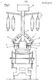
- Fig. 1 ein Querschnitt durch eine doppelseitige Ringspinnmaschine mit erfindungsgemässer Fadenabsaugvorrichtung,
- Fig. 2 eine Längsansicht der erfindungsgemässen Fadenabsaugvorrichtung, schematisch dargestellt,
- Fig. 3 ein Geschwindigkeitsdiagramm der Luft im zweiten Kanal,
- Fig. 4 ein Geschwindigkeitsdiagramm der Luft im Absaugkanal,
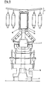
- Fig. 5 ein Querschnitt durch die Ringspinnmaschine von Fig. 1 mit je einer Variante der erfindungsgemässen Fadenabsaugvorrichtung.
- 1 shows a cross section through a double-sided ring spinning machine with a thread suction device according to the invention,
- Fig. 2 is a longitudinal view of the invention Thread suction device, shown schematically,
- 3 is a speed diagram of the air in the second channel,
- 4 shows a speed diagram of the air in the suction duct,
- 5 shows a cross section through the ring spinning machine of FIG. 1, each with a variant of the thread suction device according to the invention.
In einer Ringspinnmaschine 1 ist ein Absaugkanal 2 mittels zweier Träger 3 auf einem der Einfachheit halber als Unterteil 4 bezeichneten Teil der Ringspinnmaschine abgestützt.In a
Am Absaugkanal 2 sind Absaugdüsen 5 angeschlossen, die je am Ausgang eines Streckwerkes 6 derart nahe am Fadenlauf (nicht gezeigt) geführt sind, dass beim Fadenbruch das vom Streckwerk 6 abgelieferte Fasermaterial abgesaugt wird. Ausserdem saugen die Düsen während dem Spinnprozess Staub und Flugfasern ab.
Oberhalb eines Spulenaufsteckgatters 7 ist ein zweiter Kanal 8 vorgesehen, der mittels senkrechter Verbindungskanäle 9 mit dem Absaugkanal 2 verbunden ist. In Figur 2 ist schematisch dargestellt, dass die Kanäle 2 und 8 in eine Saugkammer 10 münden, in welcher, z.B. ein Trommelfilter 11 vorgesehen ist, der seinerseits mit einem Saugventilator (nicht gezeigt) verbunden ist.A
Am Anfang des Absaugkanales 2 ist eine sogenannte Falschluftöffnung 12 vorgesehen. Die Oeffnung 12 und der im Absaugkanal 2 vorgesehene Unterdruck ist derart aufeinander abgestimmt, dass in einem an die Oeffnung 12 anschliessenden ersten Teil 13 des Absaugkanales 2 die Luftgeschwindigkeit am Anfang 4-5 m/sec. erreicht, um damit mit Sicherheit ein von der ersten Düse 5.1 angesaugtes Faser- und Fadenmaterial transportieren zu können.At the beginning of the
Die Querschnittsfläche des zweiten Kanales 8, sowie die Verbindungskanäle 9 sind derart gewählt, dass, wie in Figur 4 mit strichpunktierter Linie dargestellt, im Absaugkanal 2 eine mittlere Luftgeschwindigkeit VA von ca. 8.5 m/sec. erreicht wird.The cross-sectional area of the
Wird ein gleichbleibender Querschnitt (Fig. 2) des Absaugkanales gewählt, so ergibt sich ein, in Fig. 4 mit ausgezogenen Linien dargestellter, sägezahnförmiger Luftgeschwindigkeitsverlauf VA.Is a constant cross-sectional (Fig. 2) of the suction channel is selected, 4 sawtooth L results in a, in FIG. By solid lines shown, uftgeschwindigkeitsverlauf V A.
Der sägezahnförmige Geschwindigkeitsverlauf V entsteht einerseits durch die Luftabzweigung in die Verbindungskanäle 9 und anderseits durch die Luftzufuhr der Düsen 5.The sawtooth-shaped speed profile V arises, on the one hand, from the branching of air into the connecting
Der Querschnitt kann als Variante pro Stufe, d.h. von Verbindungskanal zu Verbindungskanal proportional zum zunehmenden Luftvolumen vergrössert werden, so dass der Luftgeschwindigkeitsverlauf linear wird, d.h. VA entspricht
Die in Figur 2 gezeigte Anzahl Düsen ist eine rein schematische Darstellung. Die in den Figuren 3 und 4 mit S bezeichnete Abszisse weist auf die Länge der Saugkanäle 2 oder 8 hin.The number of nozzles shown in Figure 2 is a pure one schematic representation. The abscissa labeled S in FIGS. 3 and 4 indicates the length of the
Die Querschnittsfläche der Verbindungskanäle 9 ist derart gewählt, dass bei einer mittleren Luftgeschwindigkeit
Als Regel kann deshalb angenommen werden, dass immer dann ein Verbindungskanal vorgesehen werden soll, wenn sich durch die Summe der durch die Düsen 5 angesaugten Luftmengen im Absaugkanal 2 eine Luftgeschwindigkeit V von 8-18 m/sec., vorzugsweise von 8-10 m/sec., eingestellt hat.As a rule, it can therefore be assumed that a connecting duct should always be provided when the sum of the air quantities sucked in through the
Die Zunahme der Luftgeschwindigkeit VA im in Figur 2 verkürzt dargestellten ersten Teil 13 ist in Figur 4 ebenfalls verkürzt dargestellt.The increase in air speed V A in the
Um eine Förderung des Faser- und Fadenmaterials auch in Abzweigstellen zu gewährleisten, darf im Bereich des Abzweigkanales die Luftgeschwindigkeit V nicht kleiner als 6 m/sec. sein.In order to ensure that the fiber and thread material is also conveyed in branch points, the air speed V in the region of the branch duct must not be less than 6 m / sec. be.
Der Querschnitt des zweiten Kanales 8 ist derart gewählt, dass trotz jedem Einmünden eines Verbindungskanales 9 und der damit verbundenen Erhöhung der Luftmenge die mit Figur 3 gezeigte mittlere Luftgeschwindigkeit
Die Luftmengen des Absaugkanales 2 und des zweiten Kanales 8 gelangen in den gemeinsamen Saugraum 10 und werden mittels eines der Filtertrommel 11 nachgeschalteten Saugventilators (nicht gezeigt) durch die Filtertrommel und anschliessend je nach Bestimmung weitergeführt.The air quantities of the
Der zweite Kanal 8 kann entweder, wie in Figur 2 mit einer kontinuierlichen Querschnittserweiterung oder wie mit gestrichelten Linien dargestellt, mit einer stufenweisen Querschnittserweiterung versehen werden. Im letzten Fall entspricht die reguläre Luftgeschwindigkeit VK im wesentlichen der mittleren Geschwindigkeit
Die Fig. 5 zeigt zwei Ausführungsvarianten des zweiten Kanales.5 shows two variants of the second channel.
Im einen Fall ist ein zweiter Kanal 14 zwischen dem Spulenaufsteckgatter 7 und den Streckwerken 6 vorgesehen und mittels Verbindungskanälen 15 mit dem Absaugkanal 2 verbunden. Ein spezieller Träger 16 des Aufsteckgatters 7 ist erforderlich.In one case, a
Im zweiten Fall (mit strichpunktierten Linien dargestellt) wird vorgeschlagen, einen zweiten Kanal 17 im Unterteil 4 unterzubringen, was, wie aus der Figur ersichtlich, gewisse Aenderungen am Unterteil erfordert.In the second case (shown with dash-dotted lines), it is proposed to accommodate a
Der zweite Kanal 17 ist mittels Verbindungskanälen 18 mit dem Absaugkanal 2 verbunden.The
Bei dieser Variante erfüllt der zweite Kanal 17 eindeutig ebenfalls die Funktion der Faser- und Fadenmaterialförderung.In this variant, the
Die übrigen in Figur 5 nicht bezeichneten Elemente entsprechen den Elementen der mit Fig. 1 gezeigten Ringspinnmaschine.The other elements not designated in FIG. 5 correspond to the elements of the ring spinning machine shown in FIG. 1.
Claims (9)
Priority Applications (1)
| Application Number | Priority Date | Filing Date | Title |
|---|---|---|---|
| AT82104694T ATE22123T1 (en) | 1981-07-17 | 1982-05-28 | THREAD EXTRACTION DEVICE. |
Applications Claiming Priority (2)
| Application Number | Priority Date | Filing Date | Title |
|---|---|---|---|
| CH470581 | 1981-07-17 | ||
| CH4705/81 | 1981-07-17 |
Publications (3)
| Publication Number | Publication Date |
|---|---|
| EP0070377A2 true EP0070377A2 (en) | 1983-01-26 |
| EP0070377A3 EP0070377A3 (en) | 1984-01-04 |
| EP0070377B1 EP0070377B1 (en) | 1986-09-10 |
Family
ID=4281070
Family Applications (1)
| Application Number | Title | Priority Date | Filing Date |
|---|---|---|---|
| EP82104694A Expired EP0070377B1 (en) | 1981-07-17 | 1982-05-28 | Broken thread suction device |
Country Status (7)
| Country | Link |
|---|---|
| US (1) | US4432200A (en) |
| EP (1) | EP0070377B1 (en) |
| JP (1) | JPS5818424A (en) |
| AT (1) | ATE22123T1 (en) |
| AU (1) | AU8535482A (en) |
| DE (1) | DE3273136D1 (en) |
| ES (1) | ES8307939A1 (en) |
Cited By (3)
| Publication number | Priority date | Publication date | Assignee | Title |
|---|---|---|---|---|
| DE3810588A1 (en) * | 1988-03-29 | 1989-10-12 | Zinser Textilmaschinen Gmbh | EXTRACTION DEVICE FOR A SPINNING MACHINE |
| DE4319959C2 (en) * | 1992-07-21 | 2003-01-02 | Rieter Ag Maschf | Frame for spinning machine or twisting machine |
| DE10041363B4 (en) * | 2000-08-23 | 2011-01-20 | Maschinenfabrik Rieter Ag | spinning machine |
Families Citing this family (4)
| Publication number | Priority date | Publication date | Assignee | Title |
|---|---|---|---|---|
| DD299322A5 (en) * | 1989-09-21 | 1992-04-09 | Maschinenfabrik Rieter Ag,Ch | METHOD AND DEVICE FOR FINE CLEANING OF TEXTILE FIBERS |
| CN1065361C (en) * | 1994-06-02 | 2001-05-02 | 中华映管股份有限公司 | Monocolour electron gun capable of generating multigroup electron beams |
| EP3170629B1 (en) * | 2014-07-15 | 2019-05-15 | FUJI Corporation | Inspection method |
| DE102018131767A1 (en) * | 2018-12-11 | 2020-06-18 | Saurer Spinning Solutions Gmbh & Co. Kg | Textile machine producing cross-wound bobbins |
Citations (5)
| Publication number | Priority date | Publication date | Assignee | Title |
|---|---|---|---|---|
| DE19177C (en) * | J. Blank in Heidelberg | Circulation oven for bathtubs | ||
| GB190925796A (en) * | 1909-11-09 | 1910-11-03 | William Greenwood | Improvements in and connected with Spinning and the like Frames. |
| GB627075A (en) * | 1944-09-08 | 1949-07-27 | Sulzer Ag | Improvements in or relating to devices for catching broken ends in spinning, doubling, winding and like textile machinery |
| GB635942A (en) * | 1940-10-17 | 1950-04-19 | Heinrich Thoma | Improvements in or relating to devices for collecting and removing broken ends in spinning and like machines |
| DE1265017B (en) * | 1961-11-10 | 1968-03-28 | Mackie & Sons Ltd J | Yarn break suction device, especially for double-sided spinning machines |
Family Cites Families (6)
| Publication number | Priority date | Publication date | Assignee | Title |
|---|---|---|---|---|
| US908341A (en) * | 1907-11-20 | 1908-12-29 | Stephen B Shipp | Scavenger mechanism. |
| US3018503A (en) * | 1956-12-27 | 1962-01-30 | Nippon Spindle Mfg Co Ltd | Frame cleaning device utilizing exhaust air from a suction cleaner in spinning and like operations |
| US2946174A (en) * | 1957-06-19 | 1960-07-26 | Wachovia Bank And Trust Compan | Apparatus for doffing lint collection chambers |
| US2901881A (en) * | 1958-04-10 | 1959-09-01 | Bahuson Company | Apparatus for doffing lint collection chambers |
| US2977181A (en) * | 1959-03-04 | 1961-03-28 | Parks Cramer Co | Suction cleaning system for textile machinery |
| IT1095319B (en) * | 1978-04-24 | 1985-08-10 | Marzoli & C Spa | SINGLE STRUCTURAL SECTION FRAME FOR SPINNING MACHINE, TWISTING AND SIMILAR |
-
1982
- 1982-05-28 AT AT82104694T patent/ATE22123T1/en not_active IP Right Cessation
- 1982-05-28 EP EP82104694A patent/EP0070377B1/en not_active Expired
- 1982-05-28 DE DE8282104694T patent/DE3273136D1/en not_active Expired
- 1982-06-25 AU AU85354/82A patent/AU8535482A/en not_active Abandoned
- 1982-06-28 US US06/392,625 patent/US4432200A/en not_active Expired - Fee Related
- 1982-07-15 JP JP57122278A patent/JPS5818424A/en active Granted
- 1982-07-16 ES ES514677A patent/ES8307939A1/en not_active Expired
Patent Citations (5)
| Publication number | Priority date | Publication date | Assignee | Title |
|---|---|---|---|---|
| DE19177C (en) * | J. Blank in Heidelberg | Circulation oven for bathtubs | ||
| GB190925796A (en) * | 1909-11-09 | 1910-11-03 | William Greenwood | Improvements in and connected with Spinning and the like Frames. |
| GB635942A (en) * | 1940-10-17 | 1950-04-19 | Heinrich Thoma | Improvements in or relating to devices for collecting and removing broken ends in spinning and like machines |
| GB627075A (en) * | 1944-09-08 | 1949-07-27 | Sulzer Ag | Improvements in or relating to devices for catching broken ends in spinning, doubling, winding and like textile machinery |
| DE1265017B (en) * | 1961-11-10 | 1968-03-28 | Mackie & Sons Ltd J | Yarn break suction device, especially for double-sided spinning machines |
Non-Patent Citations (2)
| Title |
|---|
| "Handbuch der Baumwollspinnerei", Johannsen/Walz, Bd. III, 5. Aufl., pp. 106-109 * |
| Handbuch "Autoconer" der Fa. Schlafhorst, Nr. 7861/2d-3.78, pp. 1.2.5+1.2.5(2) * |
Cited By (3)
| Publication number | Priority date | Publication date | Assignee | Title |
|---|---|---|---|---|
| DE3810588A1 (en) * | 1988-03-29 | 1989-10-12 | Zinser Textilmaschinen Gmbh | EXTRACTION DEVICE FOR A SPINNING MACHINE |
| DE4319959C2 (en) * | 1992-07-21 | 2003-01-02 | Rieter Ag Maschf | Frame for spinning machine or twisting machine |
| DE10041363B4 (en) * | 2000-08-23 | 2011-01-20 | Maschinenfabrik Rieter Ag | spinning machine |
Also Published As
| Publication number | Publication date |
|---|---|
| ES514677A0 (en) | 1983-08-01 |
| AU8535482A (en) | 1983-01-20 |
| EP0070377B1 (en) | 1986-09-10 |
| EP0070377A3 (en) | 1984-01-04 |
| JPH0242928B2 (en) | 1990-09-26 |
| ES8307939A1 (en) | 1983-08-01 |
| US4432200A (en) | 1984-02-21 |
| JPS5818424A (en) | 1983-02-03 |
| ATE22123T1 (en) | 1986-09-15 |
| DE3273136D1 (en) | 1986-10-16 |
Similar Documents
| Publication | Publication Date | Title |
|---|---|---|
| EP0635590B1 (en) | Double-apron drafting device | |
| DE102013112941A1 (en) | spinning machine | |
| DE1510316A1 (en) | Device on textile machines, especially in the area of the intake sections of spinning machines, for the pneumatic detection and removal of contaminants | |
| EP0070377A2 (en) | Broken thread suction device | |
| DE2059199A1 (en) | Device for picking up, sucking up and discharging textile fibers and yarns | |
| EP3369851A1 (en) | Device and method for processing an endless non-woven fabric | |
| EP1191134B1 (en) | Aprons for doubleapron-drafting machine | |
| CH623084A5 (en) | ||
| EP0924323B1 (en) | Drawing frame for spinning machines | |
| CH627798A5 (en) | PNEUMATIC CLEANING DEVICE ON THE INLET TABLE OF A SPINNING MACHINE. | |
| EP0534895B1 (en) | Stretching chamber | |
| DE2039443C3 (en) | Device for transferring a textile thread from a first treatment zone to a second treatment zone | |
| WO2003083192A1 (en) | Pneumatic compaction device for a fiber assembly and method for pneumatically compacting a fiber assembly | |
| DE4123451A1 (en) | SPIDER | |
| DE3213478C2 (en) | ||
| AT395866B (en) | Apparatus for feeding a drawn fibre roving to each of at least two ring spinning stations | |
| DE3402368A1 (en) | Open-end friction-spinning device | |
| DE4205165C1 (en) | Ring spinning frame - has electronic circuits in service unit to automatic ally piece up rovings to spun yarn with progressively improved performance | |
| DE10152747A1 (en) | Sliver drawing, for yarn spinning, has condensing station with irregular sliver tension between drawing and condensing, to give thickened zones for spinning into yarn with flame/thick knotting effects | |
| EP4299807A1 (en) | Method for forming a nonwoven from several layers of fibre webs by means of a cross-lapper, cross-lapper and use thereof | |
| AT391327B (en) | Device for feeding a drawn fibre roving to each of at least two ring spinning stations | |
| DE4210946A1 (en) | Spinning jet cleaning - uses controlled stoppage or drawing unit to stop the spinning with suction to clear a fibre bridge between drawing unit and set | |
| DE19962158A1 (en) | Appts to condense a drawn sliver at a spinning machine has a structured conveyor belt path length to the length of the sliding surface of the underpressure condensing zone to reduce wear and prevent clogging | |
| DE102017116059A1 (en) | lapper | |
| DE10060300A1 (en) | Drafting of textile fibers, e.g. on drawframe, comprises use of fluids to accelerate fibers and apply the required drafting forces |
Legal Events
| Date | Code | Title | Description |
|---|---|---|---|
| PUAI | Public reference made under article 153(3) epc to a published international application that has entered the european phase |
Free format text: ORIGINAL CODE: 0009012 |
|
| AK | Designated contracting states |
Designated state(s): AT BE CH DE FR GB IT LI NL |
|
| 17P | Request for examination filed |
Effective date: 19830606 |
|
| PUAL | Search report despatched |
Free format text: ORIGINAL CODE: 0009013 |
|
| AK | Designated contracting states |
Designated state(s): AT BE CH DE FR GB IT LI NL |
|
| GRAA | (expected) grant |
Free format text: ORIGINAL CODE: 0009210 |
|
| AK | Designated contracting states |
Kind code of ref document: B1 Designated state(s): AT BE CH DE FR GB IT LI NL |
|
| REF | Corresponds to: |
Ref document number: 22123 Country of ref document: AT Date of ref document: 19860915 Kind code of ref document: T |
|
| ITF | It: translation for a ep patent filed |
Owner name: GUZZI E RAVIZZA S.R.L. |
|
| ET | Fr: translation filed | ||
| REF | Corresponds to: |
Ref document number: 3273136 Country of ref document: DE Date of ref document: 19861016 |
|
| PLBI | Opposition filed |
Free format text: ORIGINAL CODE: 0009260 |
|
| 26 | Opposition filed |
Opponent name: ZINSER TEXTILMASCHINEN GMBH Effective date: 19870610 |
|
| NLR1 | Nl: opposition has been filed with the epo |
Opponent name: ZINSER TEXTILMASCHINEN GMBH |
|
| PGFP | Annual fee paid to national office [announced via postgrant information from national office to epo] |
Ref country code: GB Payment date: 19900417 Year of fee payment: 9 |
|
| PGFP | Annual fee paid to national office [announced via postgrant information from national office to epo] |
Ref country code: BE Payment date: 19900515 Year of fee payment: 9 |
|
| PGFP | Annual fee paid to national office [announced via postgrant information from national office to epo] |
Ref country code: NL Payment date: 19900531 Year of fee payment: 9 |
|
| PGFP | Annual fee paid to national office [announced via postgrant information from national office to epo] |
Ref country code: FR Payment date: 19910416 Year of fee payment: 10 |
|
| PGFP | Annual fee paid to national office [announced via postgrant information from national office to epo] |
Ref country code: AT Payment date: 19910425 Year of fee payment: 10 |
|
| PLBN | Opposition rejected |
Free format text: ORIGINAL CODE: 0009273 |
|
| STAA | Information on the status of an ep patent application or granted ep patent |
Free format text: STATUS: OPPOSITION REJECTED |
|
| PG25 | Lapsed in a contracting state [announced via postgrant information from national office to epo] |
Ref country code: GB Effective date: 19910528 |
|
| PG25 | Lapsed in a contracting state [announced via postgrant information from national office to epo] |
Ref country code: BE Effective date: 19910531 |
|
| 27O | Opposition rejected |
Effective date: 19901217 |
|
| NLR2 | Nl: decision of opposition | ||
| BERE | Be: lapsed |
Owner name: MASCHINENFABRIK RIETER A.G. Effective date: 19910531 |
|
| PG25 | Lapsed in a contracting state [announced via postgrant information from national office to epo] |
Ref country code: NL Effective date: 19911201 |
|
| NLV4 | Nl: lapsed or anulled due to non-payment of the annual fee | ||
| GBPC | Gb: european patent ceased through non-payment of renewal fee | ||
| PG25 | Lapsed in a contracting state [announced via postgrant information from national office to epo] |
Ref country code: AT Effective date: 19920528 |
|
| PG25 | Lapsed in a contracting state [announced via postgrant information from national office to epo] |
Ref country code: FR Effective date: 19930129 |
|
| REG | Reference to a national code |
Ref country code: FR Ref legal event code: ST |
|
| ITTA | It: last paid annual fee | ||
| PGFP | Annual fee paid to national office [announced via postgrant information from national office to epo] |
Ref country code: DE Payment date: 19960422 Year of fee payment: 15 |
|
| PGFP | Annual fee paid to national office [announced via postgrant information from national office to epo] |
Ref country code: CH Payment date: 19960502 Year of fee payment: 15 |
|
| APAC | Appeal dossier modified |
Free format text: ORIGINAL CODE: EPIDOS NOAPO |
|
| APAC | Appeal dossier modified |
Free format text: ORIGINAL CODE: EPIDOS NOAPO |
|
| PG25 | Lapsed in a contracting state [announced via postgrant information from national office to epo] |
Ref country code: LI Free format text: LAPSE BECAUSE OF NON-PAYMENT OF DUE FEES Effective date: 19970531 Ref country code: CH Free format text: LAPSE BECAUSE OF NON-PAYMENT OF DUE FEES Effective date: 19970531 |
|
| REG | Reference to a national code |
Ref country code: CH Ref legal event code: PL |
|
| PG25 | Lapsed in a contracting state [announced via postgrant information from national office to epo] |
Ref country code: DE Free format text: LAPSE BECAUSE OF NON-PAYMENT OF DUE FEES Effective date: 19980203 |
|
| APAH | Appeal reference modified |
Free format text: ORIGINAL CODE: EPIDOSCREFNO |