EP0070205A1 - Dispositif pour fixer une poignée à un ustensile culinaire et procédé s'y rapportant - Google Patents
Dispositif pour fixer une poignée à un ustensile culinaire et procédé s'y rapportant Download PDFInfo
- Publication number
- EP0070205A1 EP0070205A1 EP82400275A EP82400275A EP0070205A1 EP 0070205 A1 EP0070205 A1 EP 0070205A1 EP 82400275 A EP82400275 A EP 82400275A EP 82400275 A EP82400275 A EP 82400275A EP 0070205 A1 EP0070205 A1 EP 0070205A1
- Authority
- EP
- European Patent Office
- Prior art keywords
- rivet
- bore
- stud
- handle
- metal
- Prior art date
- Legal status (The legal status is an assumption and is not a legal conclusion. Google has not performed a legal analysis and makes no representation as to the accuracy of the status listed.)
- Withdrawn
Links
Images

Classifications
-
- A—HUMAN NECESSITIES
- A47—FURNITURE; DOMESTIC ARTICLES OR APPLIANCES; COFFEE MILLS; SPICE MILLS; SUCTION CLEANERS IN GENERAL
- A47J—KITCHEN EQUIPMENT; COFFEE MILLS; SPICE MILLS; APPARATUS FOR MAKING BEVERAGES
- A47J45/00—Devices for fastening or gripping kitchen utensils or crockery
- A47J45/06—Handles for hollow-ware articles
- A47J45/061—Saucepan, frying-pan handles
Definitions
- the present invention relates to a device for attaching a handle to a cooking utensil such as a pan, frying pan, cooking pot and the like.
- the invention also relates to the method for attaching a handle to a cooking utensil by means of the aforementioned device.
- Known fastening devices of this type generally comprise a metal stud fixed for example by welding, to the side wall of the utensil, this stud comprising a threaded axial bore into which is screwed a screw which is engaged in an orifice provided in the end of the handle.
- this stud fixed for example by welding, to the side wall of the utensil, this stud comprising a threaded axial bore into which is screwed a screw which is engaged in an orifice provided in the end of the handle.
- the fixing is consolidated by a metal base fixed to the utensil-around the stud and in which the end of the handle is fitted.
- the object of the present invention is to create fixing devices which avoid the use of screws and which allow an inseparable and irreversible fixing, while being inexpensive and easy to assemble.
- the fixing device covered by the invention comprises a metal stud intended to be fixed to the utensil, and a metal rivet fixed or intended to be fixed to this stud, this rivet comprising means for allowing the fixing of the handle to this rivet.
- this device is characterized in that the rivet comprises at one of its ends a radially deformable part under the effect of a force applied axially on the rivet and making it possible to make this rivet integral with the handle and of the stud.
- This radial deformation of the rivet makes it possible to obtain a solid and irreversible fixing of the handle, by means of a single operation, namely the application of an axial force to the rivet.
- the metal stud intended to be fixed to the utensil carries a bore to receive a metal rivet serving to fix the handle to this stud, the diameter of this rivet being substantially identical to that of this bore, the bore of the stud comprising means which ensure a radial deformation of the rivet and an anchoring of the latter in the bore of the stud under the effect of an applied force axia-. on the rivet.
- the anchoring produced in the bore of the stud which results from the radial deformation of the rivet makes it possible to obtain a solid and irreversible fixing of the handle, by means of a single operation, namely the application of an axial force on the rivet.
- This axial force is of course adjusted as a function in particular of the metals or alloys in which the stud and the screw are made and of the solidity of the fixing which one wishes to obtain which itself itself depends in particular on the weight of the utensil.
- Such a fixing device thus avoids the use of screws liable to loosen during use.
- an annular groove coaxial with the bore, the external diameter of this groove being greater than that of the bore, the end of the rivet adjacent to the bottom of the bore comprising an axial recess which defines a tubular part, the latter being intended to penetrate by deformation at least partly in this groove under the effect of a force applied axially on the rivet.
- the lateral surface of the stud bore comprises at least one recess, the lateral surface of the rivet being intended to penetrate into this recess by radial deformation of the metal under the effect of an applied force axially on the rivet.
- a metal ball having a diameter less than that of the bore, the end of the rivet adjacent to the bottom of the bore having an axial recess defining a tubular part, the latter being intended to engage around the ball by deformation of the metal under the effect of a force applied radially to the rivet.
- the bore of the stud does not require any additional tapping or drilling operations.
- the tubular part of the rivet is retained by deformation of the latter and expansion of the bore of the stud around the ball.
- the method according to the invention using any of the aforementioned fixing devices consists in applying axially to the head of the rivet a force of between 500 and 2000 kg.
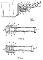
- the device for fixing the handle 1 for example bakelite to the pan 2 mainly comprises a stud 3 substantially cylindrical welded to the side wall 4 of the pan and a rivet 5 engaged in a bore 6 of this stud 3, the head 7 of the rivet 5 making the end of the handle 1 integral with the stud 3.
- the rivet 5 is engaged in an orifice 9 formed in the end 8 of the handle 1.
- the latter comprises d on the other hand a cavity 10 which is fitted around the stud 3.
- the attachment of the handle 1 to the pan 2 is consolidated by a metal base 11 which is welded to the side wall 4 around the stud 3, and in which the end 8 of the handle 1 is fitted.
- annular groove 13 coaxial with the bore 6 and whose outer diameter is greater than that of this bore 6
- This groove 13 is frustoconical and flared towards the end 3a of the stud 3 which is intended to be fixed by welding to the pan 2.
- the end of the rivet 5 adjacent to the bottom 12 of the bore 6 of the stud 3 has an axial bore 14 defining a tubular part 15.
- the latter is intended to penetrate by deformation in the groove 13 under the effect of a force F applied axially to the head 7 of the rivet 5, as shown in FIG. 3.
- the width d of the groove 13 is substantially equal to the thickness e of the wall 15 which defines the tubular part of the rivet 5.
- the depth of the groove 13 is at least equal to the thickness e of this wall 14. Preferably, this depth is substantially equal to twice the thickness e as is the case in the embodiment shown in FIGS. 2 and 3.
- this rivet 5 is made of a non-brittle and relatively deformable metal or metal alloy such as aluminum or mild steel.
- the choice of metal or metal alloy constituting the stud 3 essentially depends on that in which the pan 2 is made, taking into account the possibilities of welding between these metals or alloys. Thus, since the pan 2 is generally made of steel or aluminum, the stud 3 will most often be made of aluminum or steel.
- An axial force F of between 500 and 2000 kg is then applied to the head 7 of the rivet 5, for example by means of a press or a vibrating hammer.
- the fixation thus obtained is irreversible. Only a very high traction exerted along the axis of the handle 1 could possibly lead to a release of the tubular part 15 relative to the annular groove 13. However, under normal and even accidental conditions of use of a pan, a such axial traction can in no way occur. The binding thus obtained is therefore extremely reliable.
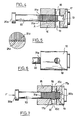
- the stud 16 has a bore 18 which passes right through it perpendicularly to the axis of its bore 17.
- This bore 18 opens radially inside the bore 17 and is located near the bottom 19 of the latter. In the example shown, this bore 18 has a section close to that of bore 17.
- the rivet 20 has on its part intended to be engaged in the bore 17 of the stud 16 of the annular grooves 21a (see FIG. 5) whose sharp edges are flush with the cylindrical and smooth surface of the bore 17.
- an axial force F of between 500 and 2000 kg is applied as previously to the head 20a of the rivet 20.
- the end 20b of the rivet 20 bears against the bottom 19 of the bore 17 and its surface 20c located opposite the holes 18 expands by partially penetrating into the latter.
- the expansion of the surface 20c of the rivet 20 causes .correlatively a slight expansion of the bore 17 at the entrance 17a of the holes 18. This also results in a depression of the sharp-edged ridges 21a of the rivet 20 in the surface of the bore 17 at the inputs 17a of the holes 18.
- the stud 16 and the rivet 20 are made of aluminum, mild steel or metal or alloy having mechanical properties similar to the latter.
- FIGS. 4 to 7 has the advantage of being a little simpler than that of FIGS. 1 to 3, because the drilling 18 is simpler to execute than the annular groove 13.
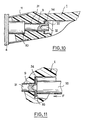
- a metal ball 24 preferably of hard steel having a diameter less than that of the bore 22.
- the end of the rivet 25 engaged in the bore 22 has an axial recess 26 which defines a tubular part 27.
- the difference between the diameter of the ball 24 and that of the bore 22 is less than twice the thickness of the wall 27 which constitutes the tubular part of the rivet 25.
- the thickness of the wall 27 of this tubular part is less than the clearance existing between the ball 24 and the bore 22, assuming that this clearance is regularly distributed around this ball.
- the bottom 23 of the bore 22 is a portion of a sphere whose radius is slightly greater than that of the ball 24.
- the lateral surface of the rivet 25 carries annular ridges 28 with sharp edges.
- the stud 21 and the rivet 25 are preferably made of aluminum or mild steel.
- the thickness of the wall 27 of the tubular end of the rivet 25 is less than the clearance existing between the ball 24 and the bore 22, this wall 27 tends to expand the internal surface of the bore 22 in the zone located opposite the ball 24. This results in an anchoring of the tubular part 27 of the rivet on the internal surface of the bore 22. This anchoring is reinforced due to the insertion of the grooves 28 of the rivet 25 in the internal surface of the bore 22.
- the stud 30 is made in one piece with the rivet 31.
- the end of this rivet opposite the stud 30 has an axial bore 32 which defines a tubular part 33.
- This tubular part 33 is deformable radially outward by applying to it by means of the tool 35 an axial force F.
- This tubular part 33 thus folds against the optional washer 34 applied to the inlet of the bore 9 formed in the body of the handle 1. This gives a solid and irreversible fixing of the handle 1 to the assembly constituted by the rivet 31 and the stud 30.
- the bore 18 formed in the bore 17 of the stud 16 could be replaced by a single recess opening into the interior of this bore.
- the expansion of the tubular part 15 could be facilitated by providing in this part longitudinal slots extending along the axis of the rivet 5.
- the ridges 28 of the rivet 25 could be replaced by a thread and the bore 22 of the stud 21 could include an additional thread.
- the axial force applied to the rivet 25 would be brought into play by screwing the rivet 25 against the bottom of the stud bore. Such a screwing would however be irreversible due to the crushing of the end of the tubular part 27 of the rivet between the internal surface of the bore 22 of the stud and the ball 24.
Landscapes
- Engineering & Computer Science (AREA)
- Food Science & Technology (AREA)
- Insertion Pins And Rivets (AREA)
- Cookers (AREA)
Applications Claiming Priority (2)
| Application Number | Priority Date | Filing Date | Title |
|---|---|---|---|
| FR8111905 | 1981-06-17 | ||
| FR8111905A FR2507883A1 (fr) | 1981-06-17 | 1981-06-17 | Dispositif pour fixer une poignee a un ustensile culinaire et procede s'y rapportant |
Publications (1)
| Publication Number | Publication Date |
|---|---|
| EP0070205A1 true EP0070205A1 (fr) | 1983-01-19 |
Family
ID=9259618
Family Applications (1)
| Application Number | Title | Priority Date | Filing Date |
|---|---|---|---|
| EP82400275A Withdrawn EP0070205A1 (fr) | 1981-06-17 | 1982-02-17 | Dispositif pour fixer une poignée à un ustensile culinaire et procédé s'y rapportant |
Country Status (4)
| Country | Link |
|---|---|
| EP (1) | EP0070205A1 (enExample) |
| DE (1) | DE70205T1 (enExample) |
| ES (1) | ES509794A0 (enExample) |
| FR (1) | FR2507883A1 (enExample) |
Cited By (7)
| Publication number | Priority date | Publication date | Assignee | Title |
|---|---|---|---|---|
| US4640641A (en) * | 1984-07-25 | 1987-02-03 | Teledyne Continental Motors | Piston pin construction and method for forming same |
| AU573361B2 (en) * | 1984-07-25 | 1988-06-02 | Teledyne Industries, Inc. | Gudgeon-pin |
| EP0521795A1 (fr) * | 1991-07-05 | 1993-01-07 | Seb S.A. | Ustensile de cuisson à poignée inamovible |
| WO2009062353A1 (fr) * | 2007-11-13 | 2009-05-22 | Jianxiong Chen | Poignée métallique d'un ustensile de cuisine et ustensile |
| DE102008036551A1 (de) * | 2008-08-06 | 2010-02-11 | Wmf Württembergische Metallwarenfabrik Ag | Griffbefestigung |
| CN101385617B (zh) * | 2007-09-12 | 2011-11-30 | Seb公司 | 带有焊接座的厨具把手固定装置 |
| CN104138220A (zh) * | 2014-07-22 | 2014-11-12 | 广东小熊电器有限公司 | 一种具有可收纳手柄的煎烤器 |
Citations (7)
| Publication number | Priority date | Publication date | Assignee | Title |
|---|---|---|---|---|
| US1482765A (en) * | 1922-04-20 | 1924-02-05 | Associated Trading Corp | Molded article |
| FR779748A (fr) * | 1934-10-05 | 1935-04-11 | Aluminium Lumiere | Mode de fixation sans rivure visible des poignées, anses et autres aux récipients en aluminium |
| CH189614A (de) * | 1936-05-16 | 1937-03-15 | Merker & Co A G | Verfahren zum Befestigen von Isoliergriffen an mit einem Schutzbelag, insbesondere Email oder Lack, zu versehenden Metallgefässen. |
| GB472714A (en) * | 1936-06-27 | 1937-09-29 | London Aluminium Company Ltd | Improved means for attaching handles to hollow-ware or the like |
| FR900995A (fr) * | 1943-01-26 | 1945-07-13 | Dispositif de fixation des poignées de casseroles ou ustensiles divers | |
| DE1264711B (de) * | 1958-01-06 | 1968-03-28 | Konink Kamper Metaalfab Voorhe | Kochtopf, Pfanne, Kessel oder derartiges Gefaess fuer den Hausbedarf |
| DE2343486A1 (de) * | 1973-08-29 | 1975-03-13 | Peddinghaus Carl Dan Kg | Handwerkzeuge |
-
1981
- 1981-06-17 FR FR8111905A patent/FR2507883A1/fr active Granted
-
1982
- 1982-02-17 EP EP82400275A patent/EP0070205A1/fr not_active Withdrawn
- 1982-02-17 DE DE1982400275 patent/DE70205T1/de active Pending
- 1982-02-22 ES ES509794A patent/ES509794A0/es active Granted
Patent Citations (7)
| Publication number | Priority date | Publication date | Assignee | Title |
|---|---|---|---|---|
| US1482765A (en) * | 1922-04-20 | 1924-02-05 | Associated Trading Corp | Molded article |
| FR779748A (fr) * | 1934-10-05 | 1935-04-11 | Aluminium Lumiere | Mode de fixation sans rivure visible des poignées, anses et autres aux récipients en aluminium |
| CH189614A (de) * | 1936-05-16 | 1937-03-15 | Merker & Co A G | Verfahren zum Befestigen von Isoliergriffen an mit einem Schutzbelag, insbesondere Email oder Lack, zu versehenden Metallgefässen. |
| GB472714A (en) * | 1936-06-27 | 1937-09-29 | London Aluminium Company Ltd | Improved means for attaching handles to hollow-ware or the like |
| FR900995A (fr) * | 1943-01-26 | 1945-07-13 | Dispositif de fixation des poignées de casseroles ou ustensiles divers | |
| DE1264711B (de) * | 1958-01-06 | 1968-03-28 | Konink Kamper Metaalfab Voorhe | Kochtopf, Pfanne, Kessel oder derartiges Gefaess fuer den Hausbedarf |
| DE2343486A1 (de) * | 1973-08-29 | 1975-03-13 | Peddinghaus Carl Dan Kg | Handwerkzeuge |
Cited By (9)
| Publication number | Priority date | Publication date | Assignee | Title |
|---|---|---|---|---|
| US4640641A (en) * | 1984-07-25 | 1987-02-03 | Teledyne Continental Motors | Piston pin construction and method for forming same |
| AU573361B2 (en) * | 1984-07-25 | 1988-06-02 | Teledyne Industries, Inc. | Gudgeon-pin |
| EP0521795A1 (fr) * | 1991-07-05 | 1993-01-07 | Seb S.A. | Ustensile de cuisson à poignée inamovible |
| FR2678503A1 (fr) * | 1991-07-05 | 1993-01-08 | Seb Sa | Ustensile de cuisson a poignee inamovible. |
| CN101385617B (zh) * | 2007-09-12 | 2011-11-30 | Seb公司 | 带有焊接座的厨具把手固定装置 |
| WO2009062353A1 (fr) * | 2007-11-13 | 2009-05-22 | Jianxiong Chen | Poignée métallique d'un ustensile de cuisine et ustensile |
| DE102008036551A1 (de) * | 2008-08-06 | 2010-02-11 | Wmf Württembergische Metallwarenfabrik Ag | Griffbefestigung |
| US8608020B2 (en) | 2008-08-06 | 2013-12-17 | Wmf Wurttembergische Metallwarenfabrik Ag | Handle fixture |
| CN104138220A (zh) * | 2014-07-22 | 2014-11-12 | 广东小熊电器有限公司 | 一种具有可收纳手柄的煎烤器 |
Also Published As
| Publication number | Publication date |
|---|---|
| DE70205T1 (de) | 1983-04-28 |
| FR2507883A1 (fr) | 1982-12-24 |
| ES8303066A1 (es) | 1983-02-01 |
| FR2507883B1 (enExample) | 1985-05-17 |
| ES509794A0 (es) | 1983-02-01 |
Similar Documents
| Publication | Publication Date | Title |
|---|---|---|
| EP0336833B1 (fr) | Butée réglable | |
| EP1167078B1 (fr) | Dispositif d'accrochage d'un rayon à la jante d'une roue de bicyclette | |
| EP0016669B1 (fr) | Manchon d'assemblage pour la fixation d'une vis dans un objet, notamment en matériau tendre | |
| FR2706088A1 (fr) | Connecteur pour câbles coaxiaux à tube ondulé. | |
| EP0399920B1 (fr) | Tige intramédullaire pour prothèse vissée | |
| FR2638796A1 (fr) | Dispositif d'assemblage a ecrou-barillet flottant | |
| FR2647863A1 (fr) | Ensemble d'ecrou a verrouillage | |
| EP0070205A1 (fr) | Dispositif pour fixer une poignée à un ustensile culinaire et procédé s'y rapportant | |
| FR2494354A1 (fr) | Dispositif de fixation axe-ecrou | |
| EP0325069B1 (fr) | Ecrou de fixation | |
| FR2532380A1 (fr) | Dispositif d'ecrou a verrouillage positif automatique | |
| FR2575796A1 (fr) | Dispositif de fixation mecanique pour matiere fibreuse | |
| FR2756334A1 (fr) | Dispositif de fixation, support d'accrochage le comportant et son utilisation pour un pare-soleil de vehicule | |
| EP1553310B1 (fr) | Dispositif de verrouillage réversible sur une structure d'un embout à positionnement ajustable | |
| FR2502675A3 (fr) | Element de charniere | |
| FR2708063A1 (fr) | Embrayage à friction, comprenant des assemblages par rivetage en trou borgne. | |
| EP1304065B1 (fr) | Dispositif et procédé de fixation de poignée sur un article culinaire | |
| FR2683136A1 (fr) | Dispositif de fixation d'un organe de prehension sur un ustensile de cuisine. | |
| EP1691653B1 (fr) | Systeme de fixation d'une poignee de prehension a un recipient d'un article culinaire | |
| FR2699617A1 (fr) | Insert à douille et élément fileté. | |
| FR2607201A1 (fr) | Dispositif de fixation sur fut filete ou annele | |
| FR2627974A1 (fr) | Dispositif de fixation d'une poignee a un ustensile culinaire et ustensile utilisant ce dispositif | |
| EP0521795B1 (fr) | Ustensile de cuisson à poignée inamovible | |
| CH619757A5 (en) | Rivet | |
| FR2640705A1 (fr) | Insert filete perfectionne, outil pour le montage et la fixation de cet insert, et procede de montage et fixation de l'insert dans une piece quelconque a l'aide de cet outil |
Legal Events
| Date | Code | Title | Description |
|---|---|---|---|
| PUAI | Public reference made under article 153(3) epc to a published international application that has entered the european phase |
Free format text: ORIGINAL CODE: 0009012 |
|
| 17P | Request for examination filed |
Effective date: 19820220 |
|
| AK | Designated contracting states |
Designated state(s): BE DE GB IT LU NL |
|
| ITCL | It: translation for ep claims filed |
Representative=s name: BARZANO' E ZANARDO ROMA S.P.A. |
|
| ITCL | It: translation for ep claims filed |
Representative=s name: BARZANO' E ZANARDO ROMA S.P.A. |
|
| TCNL | Nl: translation of patent claims filed | ||
| DET | De: translation of patent claims | ||
| STAA | Information on the status of an ep patent application or granted ep patent |
Free format text: STATUS: THE APPLICATION IS DEEMED TO BE WITHDRAWN |
|
| 18D | Application deemed to be withdrawn |
Effective date: 19870317 |
|
| RIN1 | Information on inventor provided before grant (corrected) |
Inventor name: BUCARI, CLAUDE CHARLES |