EP0069967B1 - Device for starting fluorescent lamps - Google Patents
Device for starting fluorescent lamps Download PDFInfo
- Publication number
- EP0069967B1 EP0069967B1 EP82106018A EP82106018A EP0069967B1 EP 0069967 B1 EP0069967 B1 EP 0069967B1 EP 82106018 A EP82106018 A EP 82106018A EP 82106018 A EP82106018 A EP 82106018A EP 0069967 B1 EP0069967 B1 EP 0069967B1
- Authority
- EP
- European Patent Office
- Prior art keywords
- voltage
- starter according
- thyristor
- charging capacitor
- transformer
- Prior art date
- Legal status (The legal status is an assumption and is not a legal conclusion. Google has not performed a legal analysis and makes no representation as to the accuracy of the status listed.)
- Expired
Links
Images
Classifications
-
- H—ELECTRICITY
- H05—ELECTRIC TECHNIQUES NOT OTHERWISE PROVIDED FOR
- H05B—ELECTRIC HEATING; ELECTRIC LIGHT SOURCES NOT OTHERWISE PROVIDED FOR; CIRCUIT ARRANGEMENTS FOR ELECTRIC LIGHT SOURCES, IN GENERAL
- H05B41/00—Circuit arrangements or apparatus for igniting or operating discharge lamps
- H05B41/02—Details
- H05B41/04—Starting switches
- H05B41/042—Starting switches using semiconductor devices
Definitions
- the invention relates to a device for starting fluorescent lamps, in particular hard-to-ignite 26 mm fluorescent lamps, which in the middle area between their lamp electrodes are temporarily subjected to high voltage from the outside at least until the successful starting process, with one between the operating voltage inputs, at least until the lamp electrodes are successfully started located charging circuit series connection with a rectifier, a current limiting resistor, a charging capacitor and a high-voltage transformer and a discharge circuit connected in parallel with the charging capacitor and the high-voltage transformer, which discharges quickly when a certain voltage on the charging capacitor is exceeded.
- Normal 38 mm fluorescent lamps can be ignited and operated, for example, in a heating transformer circuit or in a starter circuit. While in the heating transformer circuit the lamp electrodes are constantly flowed through by a heating current and thus ignition at mains voltage is possible, in the starter circuit, a voltage spike ignites the fluorescent lamp between the lamp electrodes. It has been shown that the much more energy-efficient new 26 mm fluorescent lamps can be ignited and operated with the usual starter circuit, but not with the heating transformer circuit.
- this object is achieved by a discharge element which can be controlled with respect to the start and end of its operation.
- the discharge element is preferably represented by a controllable valve with a control electrode, such as a thyristor. It is further preferred that the control electrode of the thyristor is appropriately biased to ignite it from a certain voltage on the charging capacitor and can be connected to the thyristor cathode via a control element to suppress the thyristor ignition processes.
- a discharge circuit enables reliable discharge from a certain voltage on the charge capacitor and safe suppression of the discharge processes after the control element has responded.
- control element is a photoresistor in light contact with the fluorescent lamp to be ignited.
- photo resistors connected in series can also be provided, each of which is in light contact with one of several fluorescent lamps to be ignited. Since the control electrode of the thyristor is then only connected to its cathode when all the photoresistors are conductive, the high-voltage application is only interrupted after all fluorescent lamps in this group have been started.
- control element can be a timer.
- This is preferably an electrical time switch which connects the thyristor control electrode to the thyristor cathode from the application of the operating voltage up to a first point in time and then releases it again from a second point in time.
- the first and second instants are preferably adjustable.
- Such a time switch enables a versatile adaptation to the respective operating requirements and, for example, a time-delayed and time-limited application of high voltage. While the delay serves the purpose of only carrying out the high-voltage application when it is possible to ignite the fluorescent lamp after the lamp electrodes have been heated, the temporary high-voltage application should also switch off when the lamp has not been ignited for a long time.
- the high-voltage application normally ends before the second point in time, namely immediately after the lamp has been ignited, and only at the second point in time in the event of a fault. This must be set so that it occurs after the time within which the ignition of intact fluorescent lamps normally takes place.
- the high-voltage transformer can be designed as an autotransformer. Furthermore, the high-voltage transformer can be connected or connectable on the output side to a plurality of high-voltage electrodes for the same reason. Therefore, an entire group of fluorescent lamps to be lit at the same time can be started with the same device.
- bypass capacitor connected in parallel with the operating inputs of the high-voltage generator for generating a heating current flowing through the lamp electrodes to provide.
- the bypass capacitor allows a constant heating current to flow through the lamp electrodes, so that problem-free ignition is possible.
- a bridging resistor could also be used instead of the bridging capacitor, but this would have the disadvantage of generating waste heat or unnecessary energy consumption.
- this change in state can optionally be used to put the high-voltage generator out of operation due to a voltage drop. In this case, there is no need for photo resistors and timers. The latter would only be required if delayed high voltage application is desired.
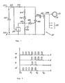
- Figure 1 shows the device according to the invention.
- a series circuit with a rectifier 34 in the form of a diode, a current limiting resistor 36, a charging capacitor 38 and a high-voltage transformer 40 In the present embodiment, the latter is an autotransformer, of which the series circuit serving as a charging circuit is a part detected.
- a discharge circuit with a thyristor 42 is located parallel to the charging capacitor 38 and the high-voltage transformer 40.
- a series circuit comprising a resistor 44, a zener diode 46 and a zener diode 48 connects the line between the current limiting resistor 36 and the charging capacitor 38 to the control electrode of the thyristor 42 Connection point 50 between the Zener diodes 46, 48 is connected via a photo resistor 52 to the cathode of the thyristor 42 or to the terminal 22.
- the high-voltage transformer 40 is connected via the high-voltage line 24 to the high-voltage electrode 16 that at least partially encompasses the fluorescent lamp 10. If necessary, the high-voltage line 24 can be connected to further high-voltage electrodes 16 via a plurality of additional connections 56.
- the high voltage generator 18 of Figure 1 operates as follows. After operating voltage is applied to the connections 20, 22 by closing the switch S from FIGS. 1, 2, the charging capacitor 38 is gradually charged in the charging circuit. As soon as its voltage has risen to a threshold value influenced by the Zener diodes 46, 48, the charging capacitor 38 takes place a sudden switching on of the thyristor 42. The sudden discharge of the charging capacitor 38 causes high-voltage peaks to be generated at the output of the high-voltage transformer 40. After a sufficient drop in the voltage at the charging capacitor 38, the thyristor 42 is blocked again because the current limiting resistor 36 prevents the thyristor holding current from being exceeded.
- the high-voltage generator 18 expediently contains a plurality of photo-resistors 52 connected in series, each of which is irradiated by one of the fluorescent lamps 10 and must all be activated before the High voltage loading is interrupted.
- an electrical timer 54 can be connected between the connection point 50 and the cathode of the thyristor 42, which, as shown, receives its supply voltage from the output of the rectifier 34.
- This controllable timer 54 can ensure that the high-voltage application is delayed in a certain way by initially closing the timer 54 and thus connecting the connection point 50 to the cathode of the thyristor 42. High-voltage pulses can only be generated after the timer 54 has been opened.
- This timer 54 can also be used to prevent high voltage exposure after a certain period of time, within which an intact fluorescent lamp 10 must have been ignited.
- the high-voltage application can normally be switched off when the fluorescent lamp 10 is ignited via the photo resistor 52 and only then via the timer 54 if, for example, an ignition process cannot be achieved as a result of a defective fluorescent lamp 10.
- a bridging capacitor 32 can also be placed between the connections 20, 22 in order to achieve the advantages explained in connection with the description of FIG. 2.
- a bypass capacitor 32 Resistor to replace, which also allows a constant flow of heating current through the lamp electrodes, not shown.
- the pulse diagram a from FIG. 2 shows a case in which a sequence of high-voltage pulses is generated between an initial point in time t o and a longest possible point in time t 3 , regardless of whether the fluorescent lamp has ignited or not.
- the high-voltage application is delayed until time t 1 , the period between t o and t 1 being used to sufficiently heat the lamp electrodes.
- the high-voltage application delayed until time t is already terminated at time t 2 , in the present case after two high-voltage pulses either by limiting this number or by switching off the high-voltage application by means of photo resistor 52 from FIG. 1. In the latter case can be switched off after a single high-voltage pulse.
- the high-voltage application begins at time t o , and then ends as in case c.
- the high-voltage electrode 16 in FIG. 1 is designed as an elastic retaining clip which is symmetrical with respect to its electrical connection and which partially surrounds the fluorescent lamp 10 in a ring-like manner. Such a high-voltage electrode 16 can have the disadvantage that it is visible during operation of the fluorescent lamp.
Abstract
Description
Die Erfindung betrifft eine Einrichtung zum Starten von Leuchtstofflampen, insbesondere von schwer zündbaren 26-mm-Leuchtstofflampen, die- im Mittenbereich zwischen ihren Lampenelektroden vorübergehend mindestens bis zum erfolgreichen Startvorgang von außen mit Hochspannung gegenüber wenigstens einer der Lampenelektroden beaufschlagt werden, mit einer zwischen den Betriebsspannungseingängen befindlichen Ladekreis-Reihenschaltung mit einem Gleichrichter, einem Strombegrenzungswiderstand, einem Ladekondensator und einem Hochspannungstransformator sowie einen parallel zum Ladekondensator sowie zum Hochspannungstransformator geschalteten Entladekreis, der beim Überschreiten einer bestimmten Spannung am Ladekondensator diesen schnell entlädt.The invention relates to a device for starting fluorescent lamps, in particular hard-to-ignite 26 mm fluorescent lamps, which in the middle area between their lamp electrodes are temporarily subjected to high voltage from the outside at least until the successful starting process, with one between the operating voltage inputs, at least until the lamp electrodes are successfully started located charging circuit series connection with a rectifier, a current limiting resistor, a charging capacitor and a high-voltage transformer and a discharge circuit connected in parallel with the charging capacitor and the high-voltage transformer, which discharges quickly when a certain voltage on the charging capacitor is exceeded.
Normale 38-mm-Leuchtstofflampen können beispielsweise in einer Heiztrafoschaltung oder in einer Starterschaltung gezündet und betrieben werden. Während bei der Heiztrafoschaltung die Lampenelektroden ständig von einem Heizstrom durchflossen werden und somit ein Zünden bei Netzspannung möglich ist, entsteht bei der Starterschaltung infolge einer Stromunterbrechung eine die Leuchtstofflampe zündende Spannungsspitze zwischen den Lampenelektroden. Es hat sich gezeigt, daß die wesentlich energiesparsameren neuen 26-mm-Leuchtstofflampen zwar mit der üblichen Starterschaltung, jedoch nicht mit der Heiztrafoschaltung gezündet und betrieben werden können.Normal 38 mm fluorescent lamps can be ignited and operated, for example, in a heating transformer circuit or in a starter circuit. While in the heating transformer circuit the lamp electrodes are constantly flowed through by a heating current and thus ignition at mains voltage is possible, in the starter circuit, a voltage spike ignites the fluorescent lamp between the lamp electrodes. It has been shown that the much more energy-efficient new 26 mm fluorescent lamps can be ignited and operated with the usual starter circuit, but not with the heating transformer circuit.
Ein derartiges Zünden von 26-mm-Leuchtstofflampen bei einer Heiztrafoschaltung ist dagegen bei der gattungsgemäßen Schaltung, wie sie in der DE-A-31 07 299 beschrieben ist, möglich.Such ignition of 26 mm fluorescent lamps in a heating transformer circuit, however, is possible with the generic circuit, as described in DE-A-31 07 299.
Dabei ist es jedoch wünschenswert, die Aufbringung des Hochspannungsimpulses in dem Mittenbereich der Leuchtstofflampe derart exakt zu steuern, daß ein zuverlässiges Zünden durch Aufbringung des Hochspannungsimpulses gewährleistet ist.However, it is desirable to control the application of the high-voltage pulse in the central region of the fluorescent lamp in such a way that reliable ignition is ensured by the application of the high-voltage pulse.
Erfindungsgemäß wird diese Aufgabe gelöst durch ein bezüglich Anfang und Ende seines Betriebes steuerbares Entladeelement.According to the invention, this object is achieved by a discharge element which can be controlled with respect to the start and end of its operation.
Vorzugsweise wird das Entladeelement durch ein steuerbares Ventil mit einer Steuerelektrode, wie einem Thyristor, dargestellt. Ferner ist es bevorzugt, daß die Steuerelektrode des Thyristors zum Zünden desselben ab einer bestimmten Spannung am Ladekondensator entsprechend vorgespannt und zum Unterdrücken der Thyristor-Zündvorgänge über ein Steuerglied mit der Thyristor-Kathode verbindbar ist. Ein solcher Entladekreis ermöglicht ein zuverlässiges Entladen ab einer bestimmten Spannung am Ladekondensator und ein sicheres Unterdrücken der Entladevorgänge nach Ansprechen des Steuergliedes.The discharge element is preferably represented by a controllable valve with a control electrode, such as a thyristor. It is further preferred that the control electrode of the thyristor is appropriately biased to ignite it from a certain voltage on the charging capacitor and can be connected to the thyristor cathode via a control element to suppress the thyristor ignition processes. Such a discharge circuit enables reliable discharge from a certain voltage on the charge capacitor and safe suppression of the discharge processes after the control element has responded.
Wenn die Hochspannungsbeaufschlagung abgebrochen werden soll, sobald die Leuchtstofflampe gezündet ist, ist es zweckmäßig, daß das Steuerglied ein mit der zu zündenden Leuchtstofflampe in Lichtkontakt stehender Fotowiderstand ist. Dabei können auch mehrere in Reihe geschaltete Fotowiderstände vorgesehen sein, die jeweils mit einer von mehreren zu zündenden Leuchtstofflampen in Lichtkontakt stehen. Da dann die Steuerelektrode des Thyristors erst dann mit dessen Kathode verbunden ist, wenn alle Fotowiderstände leitend sind, wird die Hochspannungsbeaufschlagung erst nach dem Starten aller Leuchtstofflampen dieser Gruppe unterbrochen.If the application of high voltage is to be terminated as soon as the fluorescent lamp is ignited, it is expedient for the control element to be a photoresistor in light contact with the fluorescent lamp to be ignited. Several photo resistors connected in series can also be provided, each of which is in light contact with one of several fluorescent lamps to be ignited. Since the control electrode of the thyristor is then only connected to its cathode when all the photoresistors are conductive, the high-voltage application is only interrupted after all fluorescent lamps in this group have been started.
Alternativ oder zusätzlich kann das Steuerglied ein Zeitschalter sein. Hierbei handelt es sich vorzugsweise um einen elektrischen Zeitschalter, der die Thyristor-Steuerelektrode ab dem Anlegen der Betriebsspannung bis zu einem ersten Zeitpunkt mit der Thyristor-Kathode verbindet und danach ab einem zweiten Zeitpunkt wieder freigibt. Vorzugsweise sind dabei die ersten und zweiten Zeitpunkte einstellbar. Ein solcher Zeitschalter ermöglicht eine vielseitige Anpassung an die jeweiligen Betriebserfordernisse und beispielsweise eine zeitlich verzögerte sowie zeitlich begrenzte Hochspannungsbeaufschlagung. Während die Verzögerung dem Zweck dient, die Hochspannungsbeaufschlagung erst dann vorzunehmen, wenn nach dem Aufheizen der Lampenelektroden ein Zünden der Leuchtstofflampe möglich ist, soll die zeitlich begrenzte Hochspannungsbeaufschlagung eine Abschaltung auch dann vornehmen, wenn nach einer längeren Zeit noch kein Lampenzündvorgang erfolgt ist. Hierdurch wird verhindert, daß in diesem Fall die Hochspannungsbeaufschlagung unbegrenzt fortgesetzt wird. Wenn ein solcher Zeitschalter mit den genannten Fotowiderständen kombiniert wird, erfolgt ein Beenden der Hochspannungsbeaufschlagung normalerweise bereits vor dem zweiten Zeitpunkt, nämlich unmittelbar nach dem Zünden der Lampe, und nur im Fehlerfalle zu dem zweiten Zeitpunkt. Dieser ist so einzustellen, daß er nach Ablauf derjenigen Zeit auftritt, innerhalb derer normalerweise das Zünden intakter Leuchtstofflampen erfolgt.Alternatively or additionally, the control element can be a timer. This is preferably an electrical time switch which connects the thyristor control electrode to the thyristor cathode from the application of the operating voltage up to a first point in time and then releases it again from a second point in time. The first and second instants are preferably adjustable. Such a time switch enables a versatile adaptation to the respective operating requirements and, for example, a time-delayed and time-limited application of high voltage. While the delay serves the purpose of only carrying out the high-voltage application when it is possible to ignite the fluorescent lamp after the lamp electrodes have been heated, the temporary high-voltage application should also switch off when the lamp has not been ignited for a long time. This prevents the high-voltage application from continuing indefinitely in this case. If such a time switch is combined with the photo resistors mentioned, the high-voltage application normally ends before the second point in time, namely immediately after the lamp has been ignited, and only at the second point in time in the event of a fault. This must be set so that it occurs after the time within which the ignition of intact fluorescent lamps normally takes place.
Aus Gründen einer schaltungstechnischen Vereinfachung ist es zweckmäßig, daß der Hochspannungstransformator als Spartransformator ausgebildet ist. Ferner kann der Hochspannungstransformator aus demselben Grund ausgangsseitig mit mehreren Hochspannungselektroden verbunden oder verbindbar sein. Deshalb kann eine gesamte Gruppe von gleichzeitig zu zündenden Leuchtstofflampen mit derselben Einrichtung gestartet werden.For reasons of simplification in terms of circuitry, it is expedient for the high-voltage transformer to be designed as an autotransformer. Furthermore, the high-voltage transformer can be connected or connectable on the output side to a plurality of high-voltage electrodes for the same reason. Therefore, an entire group of fluorescent lamps to be lit at the same time can be started with the same device.
Im Zusammenhang mit einer besonders vielseitig einsetzbaren Einrichtung ist es bevorzugt, einen zu den Betriebseingängen des Hochspannungsgenerators parallelgeschalteten Überbrückungskondensator zum Erzeugen eines über die Lampenelektroden fließenden Heizstroms vorzusehen. Hierdurch ist es möglich, die Einrichtung auch bei üblichen Starterschaltungen einzusetzen und anstelle des Starters anzuschließen. Der Überbrückungskondensator läßt einen ständigen Heizstrom durch die Lampenelektroden fließen, so daß ein unproblematisches Zünden möglich ist. Grundsätzlich könnte auch ein Überbrückungswiderstand statt des Überbrückungskondensators benutzt werden, was jedoch den Nachteil einer Erzeugung von Verlustwärme bzw. eines unnötigen Energieverbrauchs hätte. Wenn diese Einrichtung, also auch der Hochspannungsgenerator, direkt an die Lampenelektroden angeschlossen wird und nach dem Zünden die Lampenspannung zwischen diesen Elektroden absinkt, kann gegebenenfalls diese Zustandsänderung ausgenutzt werden, um durch Spannungsabfall den Hochspannungsgenerator außer Betrieb zu setzen. In diesem Fall kann somit auf Fotowiderstände und Zeitschalter verzichtet werden. Der letztere wäre nur erforderlich, falls eine verzögerte Hochspannungsbeaufschlagung erwünscht ist.In connection with a particularly versatile device, it is preferred to have a bypass capacitor connected in parallel with the operating inputs of the high-voltage generator for generating a heating current flowing through the lamp electrodes to provide. This makes it possible to use the device even with conventional starter circuits and to connect it instead of the starter. The bypass capacitor allows a constant heating current to flow through the lamp electrodes, so that problem-free ignition is possible. In principle, a bridging resistor could also be used instead of the bridging capacitor, but this would have the disadvantage of generating waste heat or unnecessary energy consumption. If this device, that is also the high-voltage generator, is connected directly to the lamp electrodes and the lamp voltage between these electrodes drops after ignition, this change in state can optionally be used to put the high-voltage generator out of operation due to a voltage drop. In this case, there is no need for photo resistors and timers. The latter would only be required if delayed high voltage application is desired.
Weitere Merkmale und Vorteile der Erfindung ergeben sich aus den Ansprüchen und aus der nachfolgenden Beschreibung, in der ein Ausführungsbeispiel anhand der Zeichnung im einzelnen erläutert ist. Dabei zeigt :
- Figur 1 ein Schaltbild der erfindungsgemäßen Einrichtung eines Hochspannungsgenerators nach der vorliegenden Erfindung ;
- Figur 2 ausgangsseitige Hochspannungsimpulse der Einrichtung nach der vorliegenden Erfindung in mehreren lmpulsdiagrammen.
- Figure 1 is a circuit diagram of the inventive device of a high voltage generator according to the present invention;
- Figure 2 output-side high-voltage pulses of the device according to the present invention in several pulse diagrams.
Figur 1 zeigt die erfindungsgemäße Einrichtung. Zwischen den Anschlüssen 20, 22 befindet sich eine Reihenschaltung mit einem Gleichrichter 34 in Form einer Diode, einem Strombegrenzungswiderstand 36, einem Ladekondensator 38 und einem Hochspannungstransformator 40. Der letztere ist bei der vorliegenden Ausführungsform ein Spartransformator, von dem die als Ladekreis dienende Reihenschaltung einen Teil erfaßt. Parallel zum Ladekondensator 38 und zum Hochspannungstransformator 40 befindet sich ein Entladekreis mit einem Thyristor 42. Eine Reihenschaltung aus einem Widerstand 44, einer Zenerdiode 46 und einer Zenerdiode 48 verbindet die Leitung zwischen dem Strombegrenzungswiderstand 36 und dem Ladekondensator 38 mit der Steuerelektrode des Thyristors 42. Der Verbindungspunkt 50 zwischen den Zenerdioden 46, 48 ist über einen Fotowiderstand 52 mit der Kathode des Thyristors 42 bzw. mit dem Anschluß 22 verbunden. Ausgangsseitig ist der Hochspannungstransformator 40 über die Hochspannungsleitung 24 mit der die Leuchtstofflampe 10 zumindestteilweise umfassenden Hochspannungselektrode 16 verbunden. Gegebenenfalls kann die Hochspannungsleitung 24 über mehrere Zusatzanschlüsse 56 mit weiteren Hochspannungselektroden 16 verbindbar sein.Figure 1 shows the device according to the invention. Between the connections 20, 22 there is a series circuit with a
Der Hochspannungsgenerator 18 aus Figur 1 arbeitet wie folgt. Nachdem an den Anschlüssen 20, 22 durch Schließen des Schalters S aus den Figuren 1, 2 Betriebsspannung anliegt, erfolgt in dem Ladekreis ein allmähliches Aufladen des Ladekondensators 38. Sobald dessen Spannung bis zu einem von den Zenerdioden 46, 48 beeinflußten Schwellwert angestiegen ist, erfolgt ein plötzliches Durchschalten des Thyristors 42. Durch das plötzliche Entladen des Ladekondensators 38 erfolgt am Ausgang des Hochspannungstransformators 40 eine Erzeugung von Hochspannungsspitzen. Nach einem ausreichenden Abfallen der Spannung am Ladekondensator 38 wird der Thyristor 42 wieder gesperrt, da der Strombegrenzungswiderstand 36 ein Überschreiten des Thyristor-Haltestroms verhindert. Diese Lade- und Entladevorgänge werden fortgesetzt, bis die Leuchtstofflampe 10 zündet und den Fotowiderstand 52 beleuchtet, so daß dessen Widerstand stark vermindert wird. Hierdurch wird der Verbindungspunkt 50 nahezu mit der Kathode des Thyristors 42 verbunden, so daß dieser nicht mehr zünden kann.The
Wenn an die Hochspannungsleitung 24 über die Hochspannungselektrode 16 und die Zusatzanschlüsse mehrere gleichzeitig zu zündende Leuchtstofflampen 10 angeschlossen sind, enthält der Hochspannungsgenerator 18 zweckmäßigerweise mehrere in Reihe geschaltete Fotowiderstände 52, die jeweils von einer der Leuchtstofflampen 10 bestrahlt werden und alle aktiviert sein müssen, ehe die Hochspannungsbeaufschlagung unterbrochen wird.If a plurality of fluorescent lamps 10 to be ignited are connected to the high-
Gemäß Figur 1 kann zusätzlich zu dem Fotowiderstand 52 oder anstelle desselben zwischen den Verbindungspunkt 50 und die Kathode des Thyristors 42 ein elektrischer Zeitschalter 54 geschaltet werden, der gemäß Darstellung seine Versorgungsspannung vom Ausgang des Gleichrichters 34 erhält. Dieser steuerbare Zeitschalter 54 kann dafür sorgen, daß die Hochspannungsbeaufschlagung in einer bestimmten Weise zeitlich verzögert wird, indem anfänglich ein Schließen des Zeitschalters 54 und damit ein Verbinden des Verbindungspunktes 50 mit der Kathode des Thyristors 42 erfolgen. Erst nach einem Öffnen des Zeitschalters 54 können Hochspannungsimpulse erzeugt werden. Dieser Zeitschalter 54 kann auch benutzt werden, um eine Hochspannungsbeaufschlagung nach einer bestimmten Zeitdauer zu unterbinden, innerhalb derer mit Sicherheit ein Zünden einer intakten Leuchtstofflampe 10 erfolgt sein muß. Bei einer kombinierten Anwendung des Fotowiderstandes 52 und des Zeitschalters 54 kann das Abschalten der Hochspannungsbeaufschlagung normalerweise beim Zünden der Leuchtstofflampe 10 über den Fotowiderstand 52 und erst dann über den Zeitschalter 54 erfolgen, falls beispielsweise infolge einer fehlerhaften Leuchtstofflampe 10 kein Zündvorgang erzielt werden kann.According to FIG. 1, in addition to the photo resistor 52 or instead of the same, an
Gemäß Figur 1 kann ferner zwischen die Anschlüsse 20, 22 ein Überbrückungskondensator 32 gelegt werden, um die im Zusammenhang mit der Beschreibung von Figur 2 erläuterten Vorteile zu erzielen. Grundsätzlich ist es möglich, diesen Überbrückungskondensator 32 durch einen Widerstand zu ersetzen, der ebenfalls ein ständiges Fließen eines Heizstroms durch die nicht dargestellten Lampenelektroden zuläßt.According to FIG. 1, a
Das Impulsdiagramm a aus Figur 2 zeigt einen Fall, bei dem zwischen einem anfänglichen Zeitpunkt to und einem längstmöglichen Zeitpunkt t3 eine Folge von Hochspannungsimpulsen erzeugt wird, und zwar unabhängig davon, ob die Leuchtstofflampe gezündet oder nicht gezündet hat. Im fall b wird die Hochspannungsbeaufschlagung bis zum Zeitpunkt t, verzögert, wobei der Zeitraum zwischen to und t1 zum ausreichenden Aufheizen der Lampenelektroden dienen soll. Im Fall c wird die bis zum Zeitpunkt t, verzögerte Hochspannungsbeaufschlagung bereits zum Zeitpunkt t2, beendet, und zwar im vorliegenden Fall nach bereits zwei Hochspannungsimpulsen entweder durch Begrenzen dieser Anzahl oder durch Abschaltung der Hochspannungsbeaufschlagung mittels des Fotowiderstandes 52 aus Figur 1. Im letztgenannten Fall kann die Abschaltung bereits nach einem einzigen Hochspannungsimpuls erfolgen. Im Fall d beginnt die Hochspannungsbeaufschlagung bereits mit dem Zeitpunkt to, um dann wie bei dem Fall c beendet zu werden.The pulse diagram a from FIG. 2 shows a case in which a sequence of high-voltage pulses is generated between an initial point in time t o and a longest possible point in time t 3 , regardless of whether the fluorescent lamp has ignited or not. In case b, the high-voltage application is delayed until time t 1 , the period between t o and t 1 being used to sufficiently heat the lamp electrodes. In case c, the high-voltage application delayed until time t, is already terminated at time t 2 , in the present case after two high-voltage pulses either by limiting this number or by switching off the high-voltage application by means of photo resistor 52 from FIG. 1. In the latter case can be switched off after a single high-voltage pulse. In case d, the high-voltage application begins at time t o , and then ends as in case c.
Die Hochspannungselektrode 16 ist in Figur 1 als eine in bezug auf ihren elektrischen Anschluß symmetrische, elastische Halteklammer ausgebildet, die die Leuchtstofflampe 10 ringartig teilweise umgibt. Eine solche Hochspannungselektrode 16 kann den Nachteil haben, daß sie im Betrieb der Leuchtstofflampe sichtbar ist.The high-voltage electrode 16 in FIG. 1 is designed as an elastic retaining clip which is symmetrical with respect to its electrical connection and which partially surrounds the fluorescent lamp 10 in a ring-like manner. Such a high-voltage electrode 16 can have the disadvantage that it is visible during operation of the fluorescent lamp.
Claims (11)
Priority Applications (1)
| Application Number | Priority Date | Filing Date | Title |
|---|---|---|---|
| AT82106018T ATE16673T1 (en) | 1981-07-15 | 1982-07-06 | DEVICE FOR STARTING FLUORESCENT LAMPS. |
Applications Claiming Priority (2)
| Application Number | Priority Date | Filing Date | Title |
|---|---|---|---|
| DE3127876 | 1981-07-15 | ||
| DE19813127876 DE3127876A1 (en) | 1981-07-15 | 1981-07-15 | METHOD AND DEVICE FOR STARTING FLUORESCENT LAMPS |
Publications (2)
| Publication Number | Publication Date |
|---|---|
| EP0069967A1 EP0069967A1 (en) | 1983-01-19 |
| EP0069967B1 true EP0069967B1 (en) | 1985-11-21 |
Family
ID=6136931
Family Applications (1)
| Application Number | Title | Priority Date | Filing Date |
|---|---|---|---|
| EP82106018A Expired EP0069967B1 (en) | 1981-07-15 | 1982-07-06 | Device for starting fluorescent lamps |
Country Status (4)
| Country | Link |
|---|---|
| EP (1) | EP0069967B1 (en) |
| JP (1) | JPS5893197A (en) |
| AT (1) | ATE16673T1 (en) |
| DE (2) | DE3127876A1 (en) |
Families Citing this family (5)
| Publication number | Priority date | Publication date | Assignee | Title |
|---|---|---|---|---|
| DE3437514A1 (en) * | 1984-10-12 | 1986-04-17 | Siemens AG, 1000 Berlin und 8000 München | Luminaire having a discharge lamp and an electronic ballast unit |
| US4654562A (en) * | 1984-12-21 | 1987-03-31 | The Gerber Scientific Instrument Co. | Flashing lamp unit |
| DE3642413A1 (en) * | 1986-12-11 | 1988-06-23 | Juerg Nigg | METHOD FOR INCREASING THE DETERMINATION OF DISCHARGE LAMPS, IGNITION AID ARRANGEMENT AND DISCHARGE LAMP WITH IGNITION AID |
| DE9301794U1 (en) * | 1993-02-09 | 1994-06-09 | Mutzhas Maximilian F Prof Dr I | Low voltage fluorescent tube for illuminated advertising systems |
| CN107165758B (en) * | 2017-07-26 | 2019-03-12 | 重庆理工大学 | A kind of high-current pulsed electron beam source light remote control ignition driver |
Family Cites Families (9)
| Publication number | Priority date | Publication date | Assignee | Title |
|---|---|---|---|---|
| FR997513A (en) * | 1949-09-17 | 1952-01-07 | Lighting device for fluorescent tubes | |
| GB671444A (en) * | 1949-11-01 | 1952-05-07 | Ecko Ensign Electric Ltd | Improvements in and relating to electric discharge lamps |
| GB685273A (en) * | 1950-03-14 | 1952-12-31 | British Thomson Houston Co Ltd | Improvements in and relating to starting circuits for fluorescent lamps |
| DE1772583A1 (en) * | 1968-06-06 | 1971-05-13 | Ibm Deutschland | Process for the production of a holographic filter for multiple imaging of an object and filter produced according to this process |
| GB1289118A (en) * | 1969-10-10 | 1972-09-13 | ||
| DE2355201A1 (en) * | 1973-11-05 | 1975-05-15 | Hans Kreutzinger | Electronic starter for fluorescent lamps - has controlled SC component in parallel with the lamp, operating as current valve |
| US3949267A (en) * | 1975-04-15 | 1976-04-06 | General Electric Company | Protective starting circuit for inverter operated gaseous discharge lamps |
| US4117377A (en) * | 1976-01-14 | 1978-09-26 | Jimerson Bruce D | Circuits for starting and operating ionized gas lamps |
| US4297616A (en) * | 1980-03-17 | 1981-10-27 | Xerox Corporation | Fluorescent lamp with incandescent ballasting systems |
-
1981
- 1981-07-15 DE DE19813127876 patent/DE3127876A1/en not_active Withdrawn
-
1982
- 1982-07-06 DE DE8282106018T patent/DE3267572D1/en not_active Expired
- 1982-07-06 AT AT82106018T patent/ATE16673T1/en not_active IP Right Cessation
- 1982-07-06 EP EP82106018A patent/EP0069967B1/en not_active Expired
- 1982-07-14 JP JP57122794A patent/JPS5893197A/en active Pending
Also Published As
| Publication number | Publication date |
|---|---|
| ATE16673T1 (en) | 1985-12-15 |
| JPS5893197A (en) | 1983-06-02 |
| EP0069967A1 (en) | 1983-01-19 |
| DE3127876A1 (en) | 1983-02-03 |
| DE3267572D1 (en) | 1986-01-02 |
Similar Documents
| Publication | Publication Date | Title |
|---|---|---|
| DE2323011C3 (en) | Circuit arrangement for the ignition and operation of a gas discharge lamp | |
| EP0120405B1 (en) | Ignition device for a low-pressure discharge lamp | |
| DE3811194A1 (en) | SOLID-BODY OPERATING CIRCUIT FOR A DC-DISCHARGE LAMP | |
| EP0062275A1 (en) | Ballast circuit for the operation of low-pressure discharge lamps | |
| EP0655880B1 (en) | Low voltage circuit for operating a low pressure discharge lamp | |
| DE2751464A1 (en) | STARTER TO IGNITE A GAS AND / OR VAPOR DISCHARGE LAMP | |
| EP0054301B1 (en) | Lighting circuit for a low-pressure discharge lamp | |
| EP0069967B1 (en) | Device for starting fluorescent lamps | |
| DE2802218A1 (en) | ELECTRONIC STARTER TO IGNITE A DISCHARGE LAMP | |
| DE1438857B2 (en) | Device for charging batteries | |
| DE1764624C3 (en) | Device for igniting a gas and / or vapor discharge tube by means of a high-frequency voltage and for feeding this tube | |
| DE4133027C2 (en) | Ignition device for an internal combustion engine | |
| EP0015304B1 (en) | Method and device for charging a capacitor | |
| DE19734298B4 (en) | Ignition circuit for igniting a fluorescent tube with preheatable electrodes | |
| EP0564895B1 (en) | Electronic ballast for low pressure discharge lamps | |
| EP0055995A1 (en) | Low-pressure discharge lamp starting and operating circuit using a DC source | |
| DE2849064C2 (en) | Ignition circuit for a gas discharge lamp | |
| DE3503778C2 (en) | Fluorescent lamp ballast | |
| DE2541687B2 (en) | INVERTER AND PROCEDURE FOR ITS OPERATION | |
| DE3938677A1 (en) | Fluorescent lamp starter circuit - allows several lamps to be operated from single unit | |
| DE1589306C (en) | Device for igniting and operating electric discharge lamps, especially those with ignition voltages of more than 1000 volts | |
| DE4029203C2 (en) | Arc extinguishing device for flashes for aircraft | |
| DE3140828A1 (en) | ELECTRICAL FLASH UNIT | |
| DE19513013A1 (en) | Control unit for fluorescent tube | |
| EP0552687A1 (en) | Electronic starter for fluorescent lamps |
Legal Events
| Date | Code | Title | Description |
|---|---|---|---|
| PUAI | Public reference made under article 153(3) epc to a published international application that has entered the european phase |
Free format text: ORIGINAL CODE: 0009012 |
|
| AK | Designated contracting states |
Designated state(s): AT BE CH DE FR GB IT LI NL SE |
|
| 17P | Request for examination filed |
Effective date: 19830718 |
|
| ITF | It: translation for a ep patent filed |
Owner name: FUMERO BREVETTI S.N.C. |
|
| GRAA | (expected) grant |
Free format text: ORIGINAL CODE: 0009210 |
|
| AK | Designated contracting states |
Designated state(s): AT BE CH DE FR GB IT LI NL SE |
|
| REF | Corresponds to: |
Ref document number: 16673 Country of ref document: AT Date of ref document: 19851215 Kind code of ref document: T |
|
| REF | Corresponds to: |
Ref document number: 3267572 Country of ref document: DE Date of ref document: 19860102 |
|
| ET | Fr: translation filed | ||
| PLBE | No opposition filed within time limit |
Free format text: ORIGINAL CODE: 0009261 |
|
| STAA | Information on the status of an ep patent application or granted ep patent |
Free format text: STATUS: NO OPPOSITION FILED WITHIN TIME LIMIT |
|
| 26N | No opposition filed | ||
| PGFP | Annual fee paid to national office [announced via postgrant information from national office to epo] |
Ref country code: DE Payment date: 19900329 Year of fee payment: 8 |
|
| PGFP | Annual fee paid to national office [announced via postgrant information from national office to epo] |
Ref country code: GB Payment date: 19900706 Year of fee payment: 9 |
|
| PGFP | Annual fee paid to national office [announced via postgrant information from national office to epo] |
Ref country code: CH Payment date: 19900726 Year of fee payment: 9 Ref country code: AT Payment date: 19900726 Year of fee payment: 9 |
|
| PGFP | Annual fee paid to national office [announced via postgrant information from national office to epo] |
Ref country code: FR Payment date: 19900727 Year of fee payment: 9 |
|
| PGFP | Annual fee paid to national office [announced via postgrant information from national office to epo] |
Ref country code: SE Payment date: 19900730 Year of fee payment: 9 |
|
| ITTA | It: last paid annual fee | ||
| PGFP | Annual fee paid to national office [announced via postgrant information from national office to epo] |
Ref country code: NL Payment date: 19900731 Year of fee payment: 9 |
|
| PGFP | Annual fee paid to national office [announced via postgrant information from national office to epo] |
Ref country code: BE Payment date: 19900808 Year of fee payment: 9 |
|
| PG25 | Lapsed in a contracting state [announced via postgrant information from national office to epo] |
Ref country code: DE Effective date: 19910403 |
|
| PG25 | Lapsed in a contracting state [announced via postgrant information from national office to epo] |
Ref country code: GB Effective date: 19910706 Ref country code: AT Effective date: 19910706 |
|
| PG25 | Lapsed in a contracting state [announced via postgrant information from national office to epo] |
Ref country code: SE Effective date: 19910707 |
|
| PG25 | Lapsed in a contracting state [announced via postgrant information from national office to epo] |
Ref country code: LI Effective date: 19910731 Ref country code: CH Effective date: 19910731 Ref country code: BE Effective date: 19910731 |
|
| BERE | Be: lapsed |
Owner name: LUCK HARALD Effective date: 19910731 |
|
| PG25 | Lapsed in a contracting state [announced via postgrant information from national office to epo] |
Ref country code: NL Effective date: 19920201 |
|
| GBPC | Gb: european patent ceased through non-payment of renewal fee | ||
| NLV4 | Nl: lapsed or anulled due to non-payment of the annual fee | ||
| PG25 | Lapsed in a contracting state [announced via postgrant information from national office to epo] |
Ref country code: FR Effective date: 19920331 |
|
| REG | Reference to a national code |
Ref country code: CH Ref legal event code: PL |
|
| REG | Reference to a national code |
Ref country code: FR Ref legal event code: ST |
|
| EUG | Se: european patent has lapsed |
Ref document number: 82106018.3 Effective date: 19920210 |