EP0069413B1 - Tragbares pneumatisches Drahtschneidegerät - Google Patents
Tragbares pneumatisches Drahtschneidegerät Download PDFInfo
- Publication number
- EP0069413B1 EP0069413B1 EP82200739A EP82200739A EP0069413B1 EP 0069413 B1 EP0069413 B1 EP 0069413B1 EP 82200739 A EP82200739 A EP 82200739A EP 82200739 A EP82200739 A EP 82200739A EP 0069413 B1 EP0069413 B1 EP 0069413B1
- Authority
- EP
- European Patent Office
- Prior art keywords
- cable
- movement
- response
- handle
- side members
- Prior art date
- Legal status (The legal status is an assumption and is not a legal conclusion. Google has not performed a legal analysis and makes no representation as to the accuracy of the status listed.)
- Expired
Links
- 238000005520 cutting process Methods 0.000 abstract description 17
- 229910000831 Steel Inorganic materials 0.000 description 1
- 239000012190 activator Substances 0.000 description 1
- 230000000712 assembly Effects 0.000 description 1
- 238000000429 assembly Methods 0.000 description 1
- 238000010924 continuous production Methods 0.000 description 1
- 230000001186 cumulative effect Effects 0.000 description 1
- 239000004744 fabric Substances 0.000 description 1
- 238000004519 manufacturing process Methods 0.000 description 1
- 239000010959 steel Substances 0.000 description 1
Images


Classifications
-
- H—ELECTRICITY
- H02—GENERATION; CONVERSION OR DISTRIBUTION OF ELECTRIC POWER
- H02G—INSTALLATION OF ELECTRIC CABLES OR LINES, OR OF COMBINED OPTICAL AND ELECTRIC CABLES OR LINES
- H02G1/00—Methods or apparatus specially adapted for installing, maintaining, repairing or dismantling electric cables or lines
- H02G1/005—Methods or apparatus specially adapted for installing, maintaining, repairing or dismantling electric cables or lines for cutting cables or wires, or splicing
Definitions
- This invention relates to an article of manufacture for cutting insulated wire. More specifically, it refers to a portable high speed pneumatically actuated insulated wire cutter.
- Our invention provides a multiple strand wire cutting assembly having multiple guiding elements so that optionally several different widths of multiple strand cable can be cut simultaneously at the same length.
- Our assembly consists of a housing supporting a pressure roller and a feed roller accommodating multiple strand wire from a feed reel. The wire is fed to a pair of guillotine type cutting blades. The upper blade is supported on a frame and is movable with respect to that frame by virtue of a cylinder rod actuated by an air cylinder.
- a handle on one side of the cutting device provides the stroke which feeds the cable forward and then actuates the air cylinder causing the upper blade to descend and cut the multistrand wire at a predetermined length. Reversal of the handle moves the cylinder rod upward.
- This device provides a portable assembly for easily and quickly cutting specified lengths of multistrand insulated wire so that the wire can be used in various electrical connectors.
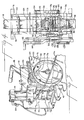
- the pneumatic wire cutter assembly 10 shown in Figure 1 contains a feed reel 12 mounted on a reel support 14. Alternately the reel can be mounted separate from the assembly 10.
- the reel support in turn is mounted on frame 16.
- Multiple strand wire 18 is fed from the feed reel 12 under a guide roller 20.
- the wire 18 then feeds over and under respectively the two supporting bars 22 and 24 and between feed roller 26 and pressure roller 28 to the cutting blades, 30 and 32.
- the lower blade 30 is permanently mounted on the base plate 40 within support frame 42, and the upper movable blade 32 moves within support frame 42.
- the blades are preferably made of carbide steel.
- the wire is severed after a predetermined length of wire 18 has moved forward and stopped between the cutting blades 30 and 32.
- cylinder rod 34 activated by the air cylinder 36 supported on mounting block 38, moves down to force blade 32 into the wire so that a clean cut is made.
- the air cylinder 36 and its mounting block 38 are supported through blade support frame 42 on a horizontal mounting plate 40.
- the support frame 42 is mounted perpendicularly to the horizontally positioned mounting plate 40.
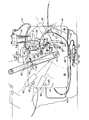
- the left side of the assembly shown in Figure 2 contains the contact roller 44 and contact stop 46 which are actuated by movement of the handle 48.
- the amount of cable fed through the assembly 10 is determined by the setting on the adjustment plate 50.
- the nut plate 52 contains two nuts 54 and 56 for mounting the adjustment plate 50 in a prescribed position in the adjusting grooves 58 and 60.
- the grooves are calibrated for various wire lengths. The further the adjustment plate 50 is moved downward the greater the distance the wire will travel before stopping and therefore, the longer will be the length of wire cut.
- An air switch 62 is mounted on the adjustment plate 50.
- the air hose 66 connects the air cylinder 36 to the air switch.
- the air source connector 68 provides the air to the air cylinder 36 by way of hose 70 and switch 62.
- Hose 72 leads to the contact stop air switch assembly 64 and hose 74 leads from that assembly to the air cylinder 36. Air pressure of 0.48-0.69 N/m 2 (70-100 psi) is adequate to perform the cutting function of this machine.
- a break ball bearing 76 supports a gear 78 that is connected via the gear on the shaft 82 to the handle 48.
- FIG. 3 shows the cutting blades in more detail.
- Top blade 32 rides within a support frame 42.
- the shaft 34 is attached to the top blade 32 by way of the alignment block 80.
- Blade 32 moves up and down in response to actuation of the air cylinder 36.
- Knife blade 30 remains fixed in the bottom of support 42 which in turn is attached to the base plate 40.
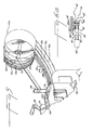
- Figure 4 shows the release spring 92 which acts in response to movement in the direction of the arrows of the pressure release 94. Movement of pressure release 94 releases the pressure roller 28 so that the wire 18 can be moved freely within the assembly. Figure 4 also shows the guide rods 86, 88 and 90 over which the wire 18 feeds into the area between the knife blades 30 and 32. A collar 96 is located below the locking bearing 76. A tray 84 is positioned below the wire 18 as it moves into the assembly. A plate 95 over the wire is also shown.
- Figure 5 shows an alternative embodiment of the invention in which more than one feed reel 12; namely 12a, b, c, d, e and f are mounted on the reel support 14.
- the cumulative width of these wires cannot exceed the width between the two sides of the frame 16 and the width of the cutting blades 30 and 32. Under normal circumstances no more than wires 18a-f will be cut simultaneously. The cutting blades will simultaneously cut all adjacent wires presented.
- FIG. 6 and 6a An alternative means of actuating the cutting blade 32 is shown in Figures 6 and 6a.
- This actuating means consists of a leaf spring 47 and an up stroke activator screw 45 mounted on the handle 48' by means of mounting plate 43. Movement of the handle 48' in a clockwise direction from the stop 49'a, 49'b or 49'c to the contact roller 44' and contact stop 46' causes both actuation of the downward and upward stroke of the blade 32.
- the air switch 62' is mounted on the adjustment plate 50'.
- the air hose 66' connects the air cylinder 36' to the air switch 62'.
- the air stop switch 64' is mounted adjacent to the air switch 62'.
- the air hose 71 feeds air to switch 64'.
- the length of wire fed through the assembly 10 is determined by the setting on the adjustment plates 50' and 50'a.
- the nuts 54' and 56' hold the plates 50' and 50'a in a prescribed position in the adjusting grooves 60' and 58' respectively.
- the pneumatic wire cutter assembly 10 normally rests on frame supports 98.
- the entire unit is sufficiently light to be able to be carried by the normal operator.
- FIGS. 1 through 6 show a handle 48 and a manual rotation of that handle it is also possible to attach an electrical apparatus so that actuation of the air switches can be carried out electrically.
Landscapes
- Removal Of Insulation Or Armoring From Wires Or Cables (AREA)
- Scissors And Nippers (AREA)
- Cigarettes, Filters, And Manufacturing Of Filters (AREA)
Claims (6)
Priority Applications (1)
| Application Number | Priority Date | Filing Date | Title |
|---|---|---|---|
| AT82200739T ATE16060T1 (de) | 1981-06-15 | 1982-06-14 | Tragbares pneumatisches drahtschneidegeraet. |
Applications Claiming Priority (2)
| Application Number | Priority Date | Filing Date | Title |
|---|---|---|---|
| US27363181A | 1981-06-15 | 1981-06-15 | |
| US273631 | 1981-06-15 |
Publications (2)
| Publication Number | Publication Date |
|---|---|
| EP0069413A1 EP0069413A1 (de) | 1983-01-12 |
| EP0069413B1 true EP0069413B1 (de) | 1985-10-09 |
Family
ID=23044765
Family Applications (1)
| Application Number | Title | Priority Date | Filing Date |
|---|---|---|---|
| EP82200739A Expired EP0069413B1 (de) | 1981-06-15 | 1982-06-14 | Tragbares pneumatisches Drahtschneidegerät |
Country Status (3)
| Country | Link |
|---|---|
| EP (1) | EP0069413B1 (de) |
| AT (1) | ATE16060T1 (de) |
| DE (1) | DE3266786D1 (de) |
Family Cites Families (5)
| Publication number | Priority date | Publication date | Assignee | Title |
|---|---|---|---|---|
| US4051749A (en) * | 1976-01-21 | 1977-10-04 | Integral Corporation | Cable insulation stripping apparatus |
| US4046045A (en) * | 1976-12-20 | 1977-09-06 | International Telephone And Telegraph Corporation | Wire splitter for round conductor flat ribbon cable |
| US4130040A (en) * | 1977-08-23 | 1978-12-19 | Amp Incorporated | Cutter assembly |
| US4257295A (en) * | 1979-02-26 | 1981-03-24 | Eubanks Engineering Co. | Multiple purpose cutter apparatus |
| US4228709A (en) * | 1979-06-04 | 1980-10-21 | Panduit Corp. | Flat cable preparation tool assembly |
-
1982
- 1982-06-14 DE DE8282200739T patent/DE3266786D1/de not_active Expired
- 1982-06-14 EP EP82200739A patent/EP0069413B1/de not_active Expired
- 1982-06-14 AT AT82200739T patent/ATE16060T1/de not_active IP Right Cessation
Also Published As
| Publication number | Publication date |
|---|---|
| EP0069413A1 (de) | 1983-01-12 |
| ATE16060T1 (de) | 1985-10-15 |
| DE3266786D1 (en) | 1985-11-14 |
Similar Documents
| Publication | Publication Date | Title |
|---|---|---|
| US4699027A (en) | Cable stripping apparatus | |
| US4476754A (en) | Automatic cable measuring and cutting machine | |
| EP0134702B1 (de) | Vorrichtung zum Schneiden von elektrischem Draht in Stücke vorbestimmter Länge | |
| US4457195A (en) | Automatic strip cutting machine | |
| GB2174626A (en) | Wire feeding, cutting and stripping apparatus | |
| US4257295A (en) | Multiple purpose cutter apparatus | |
| US4601317A (en) | Veneer slicing system | |
| US3800389A (en) | Electrical lead and harness manufacturing | |
| DE10020968A1 (de) | Kupplungslose Drahtschneideinrichtung | |
| KR20180103497A (ko) | 절단장치 | |
| US4513647A (en) | Portable pneumatic wire cutter | |
| JP4417376B2 (ja) | 切断機内でログを移動させるための装置及び方法 | |
| US4253222A (en) | Apparatus for applying assembled connector terminals to a plurality of leads | |
| EP0069413B1 (de) | Tragbares pneumatisches Drahtschneidegerät | |
| EP0233218A1 (de) | Kabelbaum-zusammenbauapparat. | |
| EP0050909B1 (de) | Vorrichtung zum Abschneiden und Abisolieren von Draht | |
| CN223352794U (zh) | 一种线缆生产用的切断装置 | |
| EP0379344A2 (de) | Blattspender | |
| US4321848A (en) | Cylindrical member processing apparatus | |
| CN207900105U (zh) | 一种柔性扁平电线冲切机构 | |
| CN215287383U (zh) | 一种软排线自动分条机 | |
| KR20180024253A (ko) | 현수막 커팅장치 | |
| US1812122A (en) | Continuous automatic shearing machine | |
| CN220445160U (zh) | 铜排批量化生产用定长切割装置 | |
| JP2527460B2 (ja) | 切断装置 |
Legal Events
| Date | Code | Title | Description |
|---|---|---|---|
| PUAI | Public reference made under article 153(3) epc to a published international application that has entered the european phase |
Free format text: ORIGINAL CODE: 0009012 |
|
| AK | Designated contracting states |
Designated state(s): AT BE CH DE FR GB IT LI LU NL SE |
|
| 17P | Request for examination filed |
Effective date: 19821230 |
|
| ITF | It: translation for a ep patent filed | ||
| GRAA | (expected) grant |
Free format text: ORIGINAL CODE: 0009210 |
|
| AK | Designated contracting states |
Designated state(s): AT BE CH DE FR GB IT LI LU NL SE |
|
| PG25 | Lapsed in a contracting state [announced via postgrant information from national office to epo] |
Ref country code: NL Effective date: 19851009 Ref country code: FR Free format text: THE PATENT HAS BEEN ANNULLED BY A DECISION OF A NATIONAL AUTHORITY Effective date: 19851009 Ref country code: BE Effective date: 19851009 |
|
| REF | Corresponds to: |
Ref document number: 16060 Country of ref document: AT Date of ref document: 19851015 Kind code of ref document: T |
|
| PG25 | Lapsed in a contracting state [announced via postgrant information from national office to epo] |
Ref country code: SE Effective date: 19851030 |
|
| REF | Corresponds to: |
Ref document number: 3266786 Country of ref document: DE Date of ref document: 19851114 |
|
| EN | Fr: translation not filed | ||
| NLV1 | Nl: lapsed or annulled due to failure to fulfill the requirements of art. 29p and 29m of the patents act | ||
| PG25 | Lapsed in a contracting state [announced via postgrant information from national office to epo] |
Ref country code: AT Effective date: 19860614 |
|
| PG25 | Lapsed in a contracting state [announced via postgrant information from national office to epo] |
Ref country code: LU Free format text: LAPSE BECAUSE OF NON-PAYMENT OF DUE FEES Effective date: 19860630 Ref country code: LI Effective date: 19860630 Ref country code: CH Effective date: 19860630 |
|
| PLBE | No opposition filed within time limit |
Free format text: ORIGINAL CODE: 0009261 |
|
| STAA | Information on the status of an ep patent application or granted ep patent |
Free format text: STATUS: NO OPPOSITION FILED WITHIN TIME LIMIT |
|
| 26N | No opposition filed | ||
| REG | Reference to a national code |
Ref country code: CH Ref legal event code: PL |
|
| PG25 | Lapsed in a contracting state [announced via postgrant information from national office to epo] |
Ref country code: DE Effective date: 19870303 |
|
| GBPC | Gb: european patent ceased through non-payment of renewal fee | ||
| PG25 | Lapsed in a contracting state [announced via postgrant information from national office to epo] |
Ref country code: GB Effective date: 19881121 |
|
| EUG | Se: european patent has lapsed |
Ref document number: 82200739.9 Effective date: 19850828 |