EP0068734A2 - Multi-stage particulate material dryer having channelized discharge - Google Patents
Multi-stage particulate material dryer having channelized discharge Download PDFInfo
- Publication number
- EP0068734A2 EP0068734A2 EP82303149A EP82303149A EP0068734A2 EP 0068734 A2 EP0068734 A2 EP 0068734A2 EP 82303149 A EP82303149 A EP 82303149A EP 82303149 A EP82303149 A EP 82303149A EP 0068734 A2 EP0068734 A2 EP 0068734A2
- Authority
- EP
- European Patent Office
- Prior art keywords
- drying
- column
- particulate material
- dryer
- columns
- Prior art date
- Legal status (The legal status is an assumption and is not a legal conclusion. Google has not performed a legal analysis and makes no representation as to the accuracy of the status listed.)
- Granted
Links
Images


Classifications
-
- F—MECHANICAL ENGINEERING; LIGHTING; HEATING; WEAPONS; BLASTING
- F26—DRYING
- F26B—DRYING SOLID MATERIALS OR OBJECTS BY REMOVING LIQUID THEREFROM
- F26B17/00—Machines or apparatus for drying materials in loose, plastic, or fluidised form, e.g. granules, staple fibres, with progressive movement
- F26B17/12—Machines or apparatus for drying materials in loose, plastic, or fluidised form, e.g. granules, staple fibres, with progressive movement with movement performed solely by gravity, i.e. the material moving through a substantially vertical drying enclosure, e.g. shaft
- F26B17/122—Machines or apparatus for drying materials in loose, plastic, or fluidised form, e.g. granules, staple fibres, with progressive movement with movement performed solely by gravity, i.e. the material moving through a substantially vertical drying enclosure, e.g. shaft the material moving through a cross-flow of drying gas; the drying enclosure, e.g. shaft, consisting of substantially vertical, perforated walls
-
- F—MECHANICAL ENGINEERING; LIGHTING; HEATING; WEAPONS; BLASTING
- F26—DRYING
- F26B—DRYING SOLID MATERIALS OR OBJECTS BY REMOVING LIQUID THEREFROM
- F26B25/00—Details of general application not covered by group F26B21/00 or F26B23/00
- F26B25/001—Handling, e.g. loading or unloading arrangements
- F26B25/002—Handling, e.g. loading or unloading arrangements for bulk goods
Definitions
- the present invention provides a gravity flow grain dryer for particulate material comprising a first generally vertical drying column having first and second opposed spaced perforate walls.
- a second generally vertical drying column having first and_second opposed spaced perforate walls is also provided, the first and second drying columns being spaced apart to provide a plenum chamber between the columns, the first perforate walls of each drying column defining the side walls of the plenum chamber.
- First and second input means are provided for introducing particulate material into the first and second drying columns, respectively.
- First and second discharge means are provided for removing particulate material from the first and second drying cclumns, respectively.
- a column type gravity flow dryer for particulate material for example, corn or other type grain.
- the dryer generally designated 10, includes a generally square-shaped housing 12 comprised of a pair of solid end walls 14 and 16 and a pair of side walls 18 and 20. Each of the side walls 18 and 20 includes solid upper and lower portions 22 and 24, respectively, and a perforate intermedite portion 26.
- the housing 12 further includes a suitable roof 28 and is supported at the bottom by suitable support means or legs 30.
- At the top of the housing 12 is a means for introducing moist particulate material or grain into the top portion of the housing, in this embodiment, a suitably sized wet grain inlet 32.
- the heater section 40 and the blower section 38 are separated by a generally horizontally disposed partition 64 which contains an airflow control means, comprising in this embodiment, a plurality of adjustable dampers 66.
- the adjustable dampers 66 are provided to control the flow of air from the hot air fan 44 to the burner 58.- In this manner, it is possible to effectively regulate the hot air flow into the housing 12 to efficiently dry a variety of different types of particulate material. For example, it may be desirable to provide a large hot ⁇ ir flow into the housing 12 for drying high moisture content corn and a much smaller hot air flow into the housing 12 for drying lower moisture content rice.
- the adjustable dampers 66 may be set in a substantially fully open position to apply a large hot air flow to dry corn or in a substantially closed position to apply a small hot air flow when drying rice.
- each of the outer drying columns 68 is a dividing wall means, in the present embodiment a generally vertical partition 76, for dividing the lower portion of each of the drying columns 68 into two generally parallel channels 78 and 80.
- Each of the channels 78 and 80 preferably contains separate discharge means, in the present embodiment metering rolls 82 and 84, respectively, for discharging particulate material from the channels 78 and 80 at predetermined rates.
- Both of the metering rolls 82 and 84 are driven by a system of drive belts and pulleys generally designated 85. As shown, the drive pulley for the metering roll 84 is of a smaller diameter than the drive pulley for metering roll 82.
- metering roll 84 rotates faster than metering roll 82 to thereby discharge grain from the innermost channel 80 at a faster rate than the grain is discharged from the outermost channel 78.
- the grain from both channels 78 and 80 is discharged by the respective metering rolls 82 and 84 into a receiving hopper 86.
- the inner drying columns 100 also have a generally vertical partition 118, which divides each column into inner and outer channels 120 and 122 in a manner corresponding to the partitions 76 for the outer drying columns 68.
- Discharge means in the form of metering rolls 124 and 126 are also provided for discharging grain from the inner and outer channels 120 and 122, respectively.
- the metering rolls 124 and 126 also turn at different predetermined rates for discharging the grain from the channels 120 and 122 at different rates.
- the metering rolls 126 adjacent the first perforate walls 108 discharge the material at a rate faster than the metering rolls 124.
- a pair of complementary modules 160 When a pair of complementary modules 160 are placed in position in the dryer housing 12 as shown in Fig. 4, they form the drying columns 68 and 100.
- the upper and lower portions of the modules 160 are suitably contoured to enable the modules to be appropriately positioned within the dryer housing 12 as shown in Fig. 4.
- the tapered perforate tubes 116 are connected to and cooperate with the hot air ducts 62 (shown in Fig. 1) for the distribution of hot air within the plenum chamber 112.
- the triangular-shaped air ducts 127 are connected to and cooperate with the cooling air ducts 56 (shown in Fig. 1) to provide a flow of cooling air when the modules 160 are in place within the dryer housing 12.
- the grain flowing down the columns adjacent to perforate walls 70 is dried more rapidly than the grain flowing down the column adjacent outer walls 26. Accordingly, as also discussed in detail above relative to Fig. 3, the grain flowing through the columns 68 adjacent perforate walls 70 is discharged from the columns 68 at a faster rate than the grain flowing down the column adjacent the perforate walls 26.
- All of the grain discharged from the outer columns 68 is received and collected in the first receiving hopper 86.
- the collected grain flows downwardly within the hopper 86 and enters the vertical tube member 88 through the openings 94.
- the rotating grain auger 90 within the vertical tube member 88 transports the grain upwardly to the top of the tube member 88 where it is discharged into the steeping chamber 96.
- the heated air passing through the inner drying columns 100 enters the central chamber 134 and is recycled back to the hot air fan 44 for reuse.
- the cooling air which has passed through the inner columns 100 and has picked up heat from the heated grain within the columns is recycled back to the hot air fan 44 in the same manner.
- the heated air passing through the outer columns 68 is too saturated with moisture which has been removed from the grain, to be of desired use in recycling, and, thus, is exhausted to the atmosphere through the outer perforate walls 26.
- the tubular structure 210 may be removed from the base portion 202 and turned over or reversed to a position as shown in Fig. 13, with the second (perforated wall) chamber 222 adjacent the base portion 2.02, and with the first (solid wall) chamber 220 being remote from the base portion 202.
- the reversal of the tubular structure 210 is accomplished by simply removing the nuts and bolts 212 from the flanges 214 and 216, reversing end-for-end the tubular structure 210, and replacing the nuts and bolts 212 through the corresponding aligned flanges 214 and 216'.
- the chamber adjacent the base portion 202 serves as a heat exchange chamber, while the chamber remote from the base portion 202 functions as a manifold chamber.
- the combustion gases pass upwardly and are exhausted to the atmosphere as shown between covering member 229, which is supported by projections 241, and flange 216.
- Ambient air is drawn into the apparatus through the air inlet means 223 (now located in the heat exchange chamber) as shown in Fig. 13,'passes around the hot vertical tubes 208 and is heated thereby. The heated ambient air is then drawn into the dryer 10 through the opening 234.
Abstract
Description
- This invention relates generally_to gravity flow dryers for particulate material and, more particularly, to a multi-stage gravity flow dryer for particulate material wherein the discharge of the dryer is channelized.
- It is often necessary or desirable to dry freshly harvested grain before it is processed or stored. Storage of grain with excess moisture may cause quality deterioration and spoilage during subsequent storage.
- The need to dry grain prior to storage has long been recognized in the art and many grain drying systems have been developed to accomplish this purpose. In many such prior systems, the grain is heated by air at a predetermined temperature during a first drying process and then the grain is quickly cooled to a desired storage temperature by exposing the grain to a flow of ambient air. One such system is the cross-flow column type grain dryer in which grain flows downwardly by gravity through a column having perforate walls and heated air is forced transversely through the perforate walls of the column to contact the grain to dry the grain or remove moisture. Typical of such cross-flow grain dryers are the grain dryers shown and described in US-A-3238640.
- While the prior art cross-flow type grain dryers are generally effective in drying grain, the entire quantity of grain is not uniformly dried. A further drawback associated with this type of prior art drying system has been that the rapid temperature change occurring as a result of exposing the wet grain to a flow of high temperature air has tended to result in stress cracking of the grain. Although several different attempts have been made to improve the cross-flow grain dryers to alleviate stress cracking, as well as to improve the quality of the grain, such attempts have had mixed success and have resulted in greater complexity in the grain drying structure. The present invention provides a multi-stage cross-flow type grain dryer which provides a greater uniformity of drying of the grain, while minimizing the problems associated with stress cracking of the grain.
- Briefly stated, the present invention provides a gravity flow grain dryer for particulate material comprising a first generally vertical drying column having first and second opposed spaced perforate walls. A second generally vertical drying column having first and_second opposed spaced perforate walls is also provided, the first and second drying columns being spaced apart to provide a plenum chamber between the columns, the first perforate walls of each drying column defining the side walls of the plenum chamber. First and second input means are provided for introducing particulate material into the first and second drying columns, respectively. First and second discharge means are provided for removing particulate material from the first and second drying cclumns, respectively. The first discharge means comprising dividing wall means extends between the spaced perforate walls for dividing at least a portion of the first column into at least two separate channels. A first discharge means is associated with a first of the channels and a second discharge means being associated with a second of each of the channels, the first channel being adjacent the first perforate wall and the first discharge means being adapted to discharge partifculate material at a rate faster than the second discharge means. Conveyor means -is employed for receiving particulate material from the first discharge means and for conveying the particulate material to the second input means. Means is also included for providing drying air to the plenum chamber, whereby the drying air passes into the first and second drying columns through the first perforate walls to dry the particulate material, the drying air being discharged from the columns through the second perforate walls.
- The foregoing summary, as well as the following detailed description of perferred embodiments of the present invention, will be better understood when read in conjunction with the accompanying drawings, in which:
- Fig. 1 is a perspective view, with parts broken away, of a grain dryer in accordance with the present invention;
- Fig. 2 is _a side elevational view of the dryer shown in Fig. 1 with the addition of an alternative air heating system;
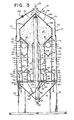
- Fig. 3 is a sectional view of a slightly modified version of the dryer of Fig. 1;
- Fig. 4 is an end elevational view of the dryer of Fig. 1 and showing the end wall removed;
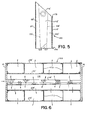
- Fig. 5 is a slightly enlarged end elevational view of a module portion of the dryer of Fig. 4 and showing the module removed from the housing;
- Fig. 6 is an enlarged plan view of the drying column module of Fig. 5;
- Fig. 7 is an enlarged side sectional view with parts broken away of the lower portion of the dryer of Fig. 2;
- Fig. 8 is a sectional view taken along the lines 8-8 of Fig. 7;
- Fig. 9 is an enlarged side elevational view of one of the dryer arrangements of a portion of Fig. 7 and showing parts broken away;
- Fig. 10 is a side elevational view, with parts broken away, of the alternative air heating system as shown added to the end of the dryer in Fig. 2;
- Fig. 11 is a greatly enlarged sectional view of a portion of the heating system of Fig. 10 taken along the lines 11-11, thereof;
- Fig. 12 is a sectional view of the heating system of Fig. 10 taken along the lines 12-12, thereof;
- - Fig. 13 is a side elevational view with parts broken away of the heating system of Fig. 10 with the upper tubular structural portion reversed; and
- Fig. 14 is a sectional view of the heating system of Fig. 13 taken along the lines 14-14, thereof,
- Referring to the drawing, and particularly to Fig. 1, there is shown a column type gravity flow dryer for particulate material, for example, corn or other type grain. The dryer, generally designated 10, includes a generally square-
shaped housing 12 comprised of a pair ofsolid end walls side walls side walls lower portions perforate intermedite portion 26. Thehousing 12 further includes asuitable roof 28 and is supported at the bottom by suitable support means orlegs 30. At the top of thehousing 12 is a means for introducing moist particulate material or grain into the top portion of the housing, in this embodiment, a suitably sizedwet grain inlet 32. ' - On the outside of the
housing 12adjacent end wall 14, is an assembly or means 34 for providing drying air and cooling air to thehousing 12. Theassembly 34, which is supported by asuitable support frame 36, generally includes ablower section 38 and a heater section 40. - The
blower section 38 comprises a pair of blowers orfans 42 and 44 both of which are mounted for rotation on asingle shaft 46. Thefan shaft 46 extends outwardly through a generally circular cooling air inlet opening 48 in theblower section 38 and is journaled for rotation within asuitable bearing 39. Asuitable drive pulley 50 is mounted on the outwardly extending end of thefan shaft 46. Thedrive pulley 50 is driven to rotation by means of a standarddrive belt system 52 which also engages asecond drive pulley 54. Thedrive pulley 54 may be driven by any suitable means, for example, an electric motor or a power takeoff mechanism on a tractor or other vehicle (not shown). - The fan 42, which is closest to the cooling air inlet opening 48, is the cool air fan and the
fan 44, which is furthest from the air inlet opening 48, is the hot air fan, the fans being separated by avertical partition 43 to form individual chambers surrounding each fan. Cooling air is drawn in through the inlet opening 48 by the cool air fan 42 and is directed into a pair ofcool air ducts 56 which in turn direct the cooling air into thedryer housing 12. Thehot air fan 44 draws air in through a second generally rectangular air inlet opening 49 located in the otherhousing end wall 16 at the opposite end of the housing and thehot air fan 44 directs the flow of air upwardly into the heater section 40. The heater section 40 includes a burner 58 which heats the air received from thefan 44. In the preferred embodiment, the burner 58 may be a standard Maxon gas burner. The heated air from the burner 58 passes into acollector chamber 60 and thereafter is directed into thehousing 12 by a pair of generally cylindricalhot air ducts 62. - The heater section 40 and the
blower section 38 are separated by a generally horizontally disposed partition 64 which contains an airflow control means, comprising in this embodiment, a plurality of adjustable dampers 66. The adjustable dampers 66 are provided to control the flow of air from thehot air fan 44 to the burner 58.- In this manner, it is possible to effectively regulate the hot air flow into thehousing 12 to efficiently dry a variety of different types of particulate material. For example, it may be desirable to provide a large hot ¿ir flow into thehousing 12 for drying high moisture content corn and a much smaller hot air flow into thehousing 12 for drying lower moisture content rice. Thus, the adjustable dampers 66 may be set in a substantially fully open position to apply a large hot air flow to dry corn or in a substantially closed position to apply a small hot air flow when drying rice. - Referring now to Fig. 3, there is shown the interior configuration of the dryer of Fig. 1 with a slight variation which will hereinafter be described. The
dryer 10 comprises a pair of generally verticalouter drying columns 68, each column being defined by first and second substantially parallel opposed spacedperforate walls wet grain hopper 72 is provided at the top portion of the dryer for receiving and temporarily storing the moist grain introduced into the top of thehousing 12 through thewet grain inlet 32. Thewet grain hopper 72 is defined by theroof panels 28, the side wall uppersolid portions 22 and a pair of slopinginterior hopper walls 74. Thewet grain hopper 72 also functions to distribute the moist grain into the top portions of each of theouter drying columns 68. - In order to provide for a more uniform and less restricted grain flow through the
outer drying columns 68, the columns are tapered outwardly from top to bottom so that the width of each of the columns is greater at the bottom than at the top. By tapering the columns in this manner, the air flow is less restricted at the top of the columns (where the grain is wetter and provides a high air flow rate through the outer columns 68) than at the bottom of the columns (where the grain is drier, thereby providing for a more volume controlled airflow through the columns over their entire length. - At the bottom of each of the
outer drying columns 68 is a dividing wall means, in the present embodiment a generallyvertical partition 76, for dividing the lower portion of each of the dryingcolumns 68 into two generallyparallel channels channels channels metering roll 84 is of a smaller diameter than the drive pulley formetering roll 82. Accordingly,metering roll 84 rotates faster thanmetering roll 82 to thereby discharge grain from theinnermost channel 80 at a faster rate than the grain is discharged from theoutermost channel 78. The grain from bothchannels hopper 86. - As shown in Fig. 3, heated air from the
hot air ducts 62 passes outwardly through theouter drying columns 68 to contact and dry the grain in the columns. Since the heated air enters each of thecolumns 68 through the innerperforated walls 70, the hottest driest air impinges upon the grain on the side of the drying columns adjacent the innerperforated walls 70. As the heated air continues on its path across the columns, a certain amount of heat is lost to the grain in the columns and the air picks up and retains moisture from the grain. By the time the air reaches the grain adjacent the outermostperforate walls 26, a significant portion of the heat has been lost to the grain and the same flow of air is also somewhat moisture laden and not able to dry the grain as effectively. Thus, the drying of the grain is somewhat uneven across the column, the grain adjacent the innerperforate walls 70 becoming drier as it flows down the columns than the grain flowing down the columns adjacent the outerperforate walls 26. By controlling the downward flow rate of the grain through thecolumns 68 to have the grain adjacent the innerperforate walls 70 flow downwardly at a faster rate than the grain adjacent the outerperforate walls 26, as described above, the faster drying grain is more quickly removed from the columns and the slower drying grain is retained in the columns for a longer period of time and is exposed to the drying air for a longer period of time to promote more uniform drying across the column. In this manner, not only is all of the grain discharged into the receivinghopper 86 with a.more uniform moisture content, but, by having the grain adjacent the innerperforate wall 70 moving more rapidly down through the columns, the problems of grain cracking and checking inherent in prior art grain dryers are reduced, since the rapidly dried grain is exposed to the hottest driest air for a shorter period of time. - In order to further control the division of the grain into the
channels partitions 78 is provided with an adjustable or pivotable section ordivider 79. The adjustable orpivotable sections 79 may be adjusted depending upon the initial moisture content and'type of grain being dried to change the relative proportions of the grain entering thechannels pivotable sections 79 to provide for a smaller portion of the grain flowing intochannels 80 than is flowing intochannels 78. In this manner, more of the corn is retained in the dryingcolumns 68 for a longer time period. Correspondingly, when drying corn with a very low moisture content, it may be desirable to adjust thepivotable sections 79 to provide for a larger portion of the grain flowing intochannels 80 than is flowing intochannels 78, thereby discharging more of the corn from the dryer in a shorter time period. Thus, by adjusting the position of thepivotable sections 79 in conjunction with the predetermined discharge rate from each of thechannels - The uniformly dried grain discharged from each of the
channels outer drying columns 68 is received and collected in the receivinghopper 86. Mounted generally in the centre of the receivinghopper 86 is atube member 88 which extends vertically upwardly into thedryer housing 12. Located within thevertical tube member 88 is a conveyor means, for example, agrain carrying auger 90 which is driven to rotation by means of asuitable drive pulley 92 extending outwardly from the bottom of the receivinghopper 86. Thedrive pulley 92 may be driven by any suitable means, for example, an electric motor or the power takeoff from a tractor or other vehicle (not shown). - The lower end of the
tube member 88 contains a plurality ofopenings 94 which allow the partially dried grain from theouter columns 68 which has accumulated within the receivinghopper 86 to pass into thetube member 88. The grain passing into thetube member 88 is conveyed or transported upwardly by the rotatinggrain auger 90 and is discharged from thetube member 88 into a substantially enclosed inner chamber 96. In the present embodiment, the rotation of thegrain auger 90 is sufficient to evenly distribute the grain discharged from thetube member 88 over the inner chamber 96. However, in a larger model of the dryer having a larger inner chamber 96, cross-augers or other suitable means (not shown) may be employed to provide an even distribution of the grain across the length and width of the inner chamber 96. - The inner chamber 96 serves as a steeping or tempering chamber for the grain. By allowing the grain to steep or sweat as it moves downwardly through the chamber 96, the moisture removal efficiency, drying uniformity and quality of the grain is greatly improved. Preferably, the grain remains in the steeping chamber for at least one hour. The sloping lower walls 98 of the steeping chamber 96 are at an angle of not less than 45° in order to provide for an acceptable flow of the moist grain downwardly through the steeping chamber. The sloping lower walls 98 of the steeping chamber include
suitable insulation 102 to prevent the grain flowing through the steeping chamber adjacent the lower walls 98 from becoming overheated due to its proximity to the incoming heated air passing through thehot air ducts 62. Theupper walls 74 of the steeping chamber 96 are also sloped at an angle of not less than 45° to assure an acceptable flow of the incoming moist grain from thewet grain inlet 32 into theouter drying columns 68. - In order to provide for most efficient use of the steeping chamber 96, it should be preferably kept full of grain. To this end, the upper steeping
chamber walls 74 include means, for example, a plurality ofslots 106 extending therethrough which allow some of the incoming moist grain to pass directly into the steeping chamber 96, in order to make up for any shrinkage of the grain which may have occurred as a result of the drying of the grain as it passed through theouter drying columns 68. Theslots 106 may also be employed to control the moisture content of the grain in the steeping chamber in a manner which will hereinafter become apparent.- In the steeping chamber, the moisture in the grain tends to be uniformly distributed amongst all the grain in the chamber. - The
roof 28 may also contain a level control means 104 positioned slightly above theslots 106. The level control means 104 functions to actuate an elevator bucket or infeed auger (not shown) to maintain the grain in thewet grain hopper 72 at a level above theslots 106 in order to ensure that there is sufficient moist grain available for adding to the steeping chamber 96 to make up for any shrinkage which may have occurred. - The grain in the steeping chamber 96 flows downwardly at a controlled rate and passes into a pair of
inner drying columns 100 which are also comprised of first and secondperforate walls perforate walls 108 cooperate withperforate walls 70 and with thehousing end walls enclosed glenum chambers 112. Theplenum chambers 112 receive the heated air from thehot air ducts 62 and distribute the heated air so that it passes outwardly through theouter drying columns 68 and inwardly through theinner drying columns 100 along the entire length of the columns. Theplenum chambers 112 may include suitable adjustable damper means 114 extending across theplenum chambers 112 between theend walls outer drying columns plenum chamber 112 to force more air through the upper section of thecolumns plenum chambers 112, the openings of the adjustable damper means 114 are tapered extending across the plenum chambers with the larger openings beingadjacent end wall 14 or in close communication with thehot air ducts 62 to provide a generally uniform distribution of drying air into the lower portion of each plenum chamber. - Figs. 1, 4 and 6 show a slightly different structural arrangement for evenly distributing the heated air within the
plenum chambers 112. As shown in Figs. 1 and 6, a pair of tapered perforate tubes 116 (116' in Fig. 6) extend across theplenum chambers 112 between theend walls tubes 116 are connected to and communicate with thehot air ducts 62 to receive the flow of heated air therefrom. Because thetubes 116 are tapered, the amount of heated air that passes along the length of the tube is restricted, thereby providing a uniform static pressure distribution along the length of the tube to ensure a uniform airflow out of the perforations therein. The uniform air flow from the taperedtubes 116 provides a generally uniform distribution of the heated air along the tubes and throughout theplenum chamber 112, thereby providing a more uniform flow of the heated air through thecolumns tubes 116 may be replaced with constant diameter tubes (not shown) having perforations varying in size and percentage of total opening along the length of the tubes, (the end of the tubes connected to thehot air ducts 62 having the larger diameter perforations and greater percentage of openings) to provide the desired generally uniform static pressure distribution along the length of the tubes into the plenum chamber. - Referring again to Fig. 3, the
inner drying columns 100 also have a generallyvertical partition 118, which divides each column into inner andouter channels 120 and 122 in a manner corresponding to thepartitions 76 for theouter drying columns 68. Discharge means in the form of metering rolls 124 and 126 are also provided for discharging grain from the inner andouter channels 120 and 122, respectively. As with the metering rolls associated with theouter drying columns 68, the metering rolls 124 and 126 also turn at different predetermined rates for discharging the grain from thechannels 120 and 122 at different rates. Preferably, the metering rolls 126 adjacent the firstperforate walls 108 discharge the material at a rate faster than the metering rolls 124. - As shown on Figs. 1 and 3, a pair of
distribution ducts 127 having triangular cross-sections excend across theplenum chambers 112 between theend walls distribution ducts 127 is connected to the cool air ducts 55 for receiving the cooling air flow. Theducts 127 have one wall provided by theperforated walls 108, which provide for the passage of cooling air into the lower portion of theinner drying columns 100. Adjacent each of theducts 127 are small access or clean-outdoors 129 to provide for the removal of debris which may accumulate within theplenum chambers 112. - The
inner drying columns 100 may also be wider at the bottoms than at the tops in a manner similar to that of theouter drying column 68 for substantially the same reasons as discussed above. Grain from thechannels 120 and 122 of theinner drying columns 100 is discharged into a second orinner receiving hopper 130. Grain from thesecond receiving hopper 130 may be removed from the dryer by means of adischarge tube 132 and may thereafter be transported to a suitable storage facility (not shown). - The
dryer 10 also includes a centralinner chamber 134 surrounding thevertical tube member 88 and formed on opposite sides by the innermostperforate walls 110. Thecentral chamber 134 extends the entire length of the dryer betweenend walls 14 and 16 (shown on Fig. 1) and provides the conduit between thehot air fan 44 and the second air inlet opening 49 for the movement of ambient air into the inlet of thehot air fan 44. Thecentral chamber 134 also receives and collects both the heating and cooling air exhausted from theinner drying columns 100 and recycles or recirculates this exhausted air back to thehot air fan 44. By mixing the incoming ambient air with the air exhausted from theinner drying columns 100 in this manner, the air entering the heater section 40 is effectively pre-heated, thereby requiring the addition of considerably less thermal energy to raise the air to the desired or requisite drying temperature. Although the benefits of recirculating or recycling air in a grain dryer are well known, recycling heated air through an inner chamber in this manner is highly desirable because the heated recycled air is insulated by the surrounding dryer structure, thereby preventing any substantial radiation loss of the heat energy contained within the recycled air. In addition, by employing such acentral recycling chamber 134, the dryer structure can be greatly compacted. Furthermore, due to the insulation of the surrounding structure, moisture condensation and dripping problems, which have plagued some prior art recirculating dryers of other designs, are avoided. - Figs. 7, 8 and 9 show additional details of the lower portion of the dryer, including the grain discharge means. As shown on Fig. 9,
metering roll 82 is retained within a plurality of aligned spaced-aparttubular members 136. Adjacent to and above thetubular members 136 are a plurality of inverted V-shapedmembers 138, which serve as deflectors to direct the downward flow of grain intospaces 140 between thetubular members 136. Themetering roll 82 further comprises a horizontalrotating grain auger 142 disposed within thetubular members 136. The grain auger is supported by, for example, asuitable bearing 144 and is driven, for example, by means of a suitable drive pulley of the type hereinbefore described. Grain flowing downwardly in each of the channels of the drying columns is deflected by the inverted V-shapedmembers 138 into thespaces 140 between thetubular members 136 where it is received and carried by the rotatinggrain auger 142 as shown by the flow arrows. Thereafter, the grain is discharged from thegrain auger 142 through a plurality ofopenings 146 located between the lower portions of each of thetubular members 136 and the grain enters the receivinghopper 86, as shown in Fig. 3. Each of thespaces 140 between thetubular members 136 is enclosed and includes a removablebottom panel 148, which is retained in place as shown by means of a pair of supportingside flanges 150 and a pair of suitably sized U-shaped clamps 152. By removing the U-shaped clamps 152, thebottom panels 148 may be conveniently removed for cleaning out thespaces 140 and thegrain auger 142. The combination of the metering rolls and the inverted V-shapedmembers 138 provide for a uniform withdrawal of grain across each of columns of the dryer. Additional details concerning the structure and operation of the grain discharge means may be obtained from US-A-4152841. The other metering rolls 84, 124 and 126 operate and are constructed similarly to metering rolls 82. - In cross flow dryers of the type shown, it is desirable to use the same dryer to dry particulate materials or grains of widely varying dimensions. For example, it may be desirable to dry either corn or rice in the same dryer. In order to be able to dry such different types of grains in the same dryer without any considerable loss of product or drying efficiency, it is necessary to have the ability to conveniently vary the size of the openings in the dryer's perforate walls forming the drying columns.
- Referring to Figs. 5 and 6, embodiments of the invention employ
removable modules 160 to accomplish this result. Each module, generally designated 160, is complete in itself and comprises four generally parallel perforate side panels 110', 108', 70' and 26', which are fixed to a plurality of generally vertical support members or cross braces 172. In Figs. 5 and 6, primes are used to designate component parts of themodule 160, the primes being dropped when themodule 160 is installed in thedryer 10 as shown on Fig. 4 (Fig. 3 does not show the modular construction features of the dryer 10). The perforate panels 110', 108', 70' and 26' may all be of one piece construction or may be made up of a plurality of individual smaller panels which are attached to the cross braces 172. The perforate panels 110', 108', .70' and 26' cooperate to form a pair of drying columns 100' and 68' with a plenum chamber 112' therebetween. A tapered perforate tube 116', a generally triangularly-shaped distribution duct 127' in cross-section having a perforated side wall 108' as a part thereof, and a clean-out door 129' are also included as part of themodule 160 as shown. - When a pair of
complementary modules 160 are placed in position in thedryer housing 12 as shown in Fig. 4, they form the dryingcolumns modules 160 are suitably contoured to enable the modules to be appropriately positioned within thedryer housing 12 as shown in Fig. 4. The taperedperforate tubes 116 are connected to and cooperate with the hot air ducts 62 (shown in Fig. 1) for the distribution of hot air within theplenum chamber 112. Likewise, the triangular-shapedair ducts 127 are connected to and cooperate with the cooling air ducts 56 (shown in Fig. 1) to provide a flow of cooling air when themodules 160 are in place within thedryer housing 12. Suitable sealing means (not shown) may be provided to prevent air leakage from around the connection of theperforate tubes 116 and the triangular-shapedducts 127 with thehot air ducts 62 and coolingair ducts 56. A number ofsmall flanges 178 on the corners of themodules 160 engage suitablecomplementary flanges 180 on thedryer housing 12 in order to properly position and retain themodules 160 in place within thehousing 12. A plurality of sealing means, for example, neoprene flaps 182, are employed to close any gaps or openings which may occur along the joint lines where themodules 160 meet thedryer housing 12 and to prevent the leakage of any grain through any such gaps or openings. - From the above description of the
modules 160, it is readily apparent that themodules 160 may be installed or removed from thedryer housing 12 shown in Fig. 4 with relative ease. Eachdryer 10 has one or more pairs ofsuch modules 160. Each pair ofsuch modules 160 has perforate side panels 110', 108', 70' and 26' with perforations of a different size than the other pairs of modules. For example, one pair of modules have perforations ideally suited for drying rice, whereas another pair of modules will have perforations ideally suited for drying corn. In this manner, greater flexibility and drying efficiency may be achieved with a single basic dryer structure. - The
dryer 10 may be operated as a batch-type dryer or as a continuous flow-type dryer. In either type of dryer operation, an operator makes a determination as to what type of grain is to be dried and the initial moisture content of the grain. The operator then selects the appropriate pair ofmodules 160 for the grain to be dried and installs the modules in thedryer housing 12 as shown in Fig. 4. The operator also adjusts the adjustable air flow dampers 66 (shown in Fig. 1) to the proper setting to provide the desired air flow to provide optimum drying for the particular grain being dried. Likewise, the operator adjusts thepivotable sections 79 on thepartitions 76 and 118 (shown in Fig. 1) to determine the relative portion of the grain which will be rapidly discharged from thegrain columns - In operation as a continuous flow dryer (referring to Fig. 3), the dryer is then activated and the grain to be dried is fed into the
wet grain inlet 32. The grain from thewet grain inlet 32 flows downwardly into thewet grain hopper 72 and is introduced into the top of theouter drying columns 68. As the grain flows downwardly through theouter drying columns 68, heated air from theplenum chamber 112 flows outwardly through the grain to heat the grain and remove moisture therefrom. The' drying air passes outwardly through the outerperforate wall 26 to the atmosphere. As the grain flows downwardly through the column, it becomes increasingly drier due to its continued contact with the heated air. As discussed in detail above, the grain flowing down the columns adjacent to perforatewalls 70 is dried more rapidly than the grain flowing down the column adjacentouter walls 26. Accordingly, as also discussed in detail above relative to Fig. 3, the grain flowing through thecolumns 68 adjacentperforate walls 70 is discharged from thecolumns 68 at a faster rate than the grain flowing down the column adjacent theperforate walls 26. - All of the grain discharged from the
outer columns 68 is received and collected in thefirst receiving hopper 86. The collected grain flows downwardly within thehopper 86 and enters thevertical tube member 88 through theopenings 94. The rotatinggrain auger 90 within thevertical tube member 88 transports the grain upwardly to the top of thetube member 88 where it is discharged into the steeping chamber 96. - After an initial startup period, the steeping chamber 96 is generally filled with partially dried grain. Due to the relatively large size of the steeping chamber 96 with respect to the
inner drying columns 100 which receive the grain discharged from the steeping chamber, the grain introduced to the top of the steeping chamber 96 moves slowly down from the steeping chamber 96 at a predetermined uniform rate. It is anticipated that the grain remains in the steeping chamber for at least a one hour period. While within the steeping chamber, the grain is steeped or sweats in a manner well known in the art. - After passing out of the steeping chamber 96, the grain enters the
inner drying columns 100 and passes downwardly therethrough. At the top of theinner drying columns 100, the grain is again exposed to a flow of heated drying air, which passes inwardly from theplenum chambers 112, through thecolumns 100 and into thecentral chamber 134, as shown in Fig. 3. As the grain moves further down theinner columns 100, it is exposed to the cooling air which passes inwardly from the coolingair distribution ducts 127, through thecolumns 100 and into thecentral chamber 134. The dried and cooled grain is then discharged into the second orinner receiving hopper 130. The grain may then be removed from the dryer by means of thedischarge tube 132 for subsequent storage and/or use. - In addition to making up for the shrinkage of the grain within the steeping chamber 96, the
slots 106 may be employed in conjunction with the metering rolls 124 and 126 at the bottom of theinner drying columns 100 to further control the moisture content of the grain discharged from thedryer 10. More specifically, by putting the metering rolls 124 and 126 on a separate drive (not shown), the amount of wet grain which enters the steeping chamber 96 through theslots 106 may be accurately controlled. For example, by having the metering rolls 124 and 126 turning faster than the metering rolls 82 and 84 of theouter drying columns 68, the flow of wet grain through theslots 106 is increased, thereby increasing the overall moisture content of the grain in the steeping chamber and, correspondingly, increasing the overall moisture . content of the grain discharged from the dryer. By controlling the moisture content through grain mixing in this manner, thedryer 10 is better able to dry various types of grains having various initial moisture contents to a specified final moisture content. - As discussed in detail above, the heated air passing through the
inner drying columns 100 enters thecentral chamber 134 and is recycled back to thehot air fan 44 for reuse. Likewise, the cooling air which has passed through theinner columns 100 and has picked up heat from the heated grain within the columns is recycled back to thehot air fan 44 in the same manner. The heated air passing through theouter columns 68 is too saturated with moisture which has been removed from the grain, to be of desired use in recycling, and, thus, is exhausted to the atmosphere through the outerperforate walls 26. - Referring now to Figs. 2 and 10-14, there is shown an alternative apparatus generally designated 200 for providing a flow of heated air to the dryer -0. The
air heating apparatus 200 may be employed to provide direct or indirect heated air to thedryer 10. By direct heated air, it is meant that the air provided by theapparatus 200 to the dryer includes the combustion gas. By indirect heated air, it is meant that the air supplied by theapparatus 200 to the dryer contains no combustion gas. Theair heating apparatus 200 may be employed as a replacement for the burner 58 (shown in Fig. 1), when it is desirable to provide indirectly heated air to the dryer for drying certain particulate material, for example sunflower seeds, which are highly flammable. - Referring now to Fig. 10, the
air heating apparatus 200 comprises a generally vertical base portion generally designated 202 mounted on asuitable support frame 203 and includes acombustion chamber 204 having a burner orheater 206 therein. Directly above thecombustion chamber 204 is a plurality of generallyvertical exhaust tubes 208. A typical air heating apparatus may contain as many as 784 such open tubes, each tube being approximately 3 metres long. The lower end of each of thetubes 208 communicates directly with thecombustion chamber 204 for receiving the combustion gas from theburner 206. - A reversible
tubular structure 210 is releasably attached to the top of thebase portion 202 by means of a plurality of nuts andbolts 212 which extend through cooperating alignedflanges base portion 202 and thetubular structure 210. Thetubular structure 210 includes a generally horizontal partition means or partition 218 for dividing the tubular structure into two generally equalsized chambers base portion 202 on Fig. 10) has generally solid aide walls, while the second chamber 222 (remote from thebase portion 202 on Fig. 10) has side walls withperforations 223 providing air inlet means for admitting fresh ambient air into the air heating apparatus. Thetubular structure 210 may be removed from thebase portion 202 and turned over or reversed to a position as shown in Fig. 13, with the second (perforated wall)chamber 222 adjacent the base portion 2.02, and with the first (solid wall)chamber 220 being remote from thebase portion 202. The reversal of thetubular structure 210 is accomplished by simply removing the nuts andbolts 212 from theflanges tubular structure 210, and replacing the nuts andbolts 212 through the corresponding alignedflanges 214 and 216'. Whether thetubular structure 210 is in the direct heating position as shown on Fig. 10 or is reversed to the indirect heating position as shown on Fig. 13, the chamber adjacent thebase portion 202 serves as a heat exchange chamber, while the chamber remote from thebase portion 202 functions as a manifold chamber. - Referring again to Fig. 10, the
vertical tubes 208 extend upwardly from thebase portion 202, through theheat exchange chamber 220 and through a plurality ofcircular openings 224 in thehorizontal partition 218, as shown in Fig. 12, one such opening for eachtube 208. Thepartition openings 224 retain the upper ends of thevertical tubes 208 in position as shown, thepartition 218 thereby cooperating with thetubes 208 to direct the flow of combustion gas into themanifold chamber 222. The lower ends of thevertical tubes 208 are retained and supported by a pair of generallyhorizontal plates base portion 202 just above thecombustion chamber 204. As best seen in Fig. 11, the uppermost of thehorizontal plates 226 contains a plurality of generallycircular openings 230, the diameters of which correspond to the outer diameters of thevertical tubes 208. Thecircular openings 230 in the upperhorizontal plate 226 are the same in number and are aligned with theopenings 224 in thehorizontal partition 218. The lower of thehorizontal plates 228 is parallel to and spaced apart from the upperhorizontal plate 226 and includes an equal plurality of alignedcircular openings 232 having diameters substantially the same as the inside diameters of thevertical tubes 208. In this manner, the vertical tubes are suitably supported by the lowerhorizontal plate 228 and are maintained'in place by thepartition 218 and the upperhorizontal plate 226. One or more of the tubes may be conveniently removed for cleaning or replacement by simply removing coveringmember 229 and sliding the tube straight upwardly until it clears thepartition 218. The coveringmember 229 is not essential to tile operation of theair heating apparatus 200 and is provided only to protect the heating apparatus from the elements. - The
partition 218 further includes port means, for example, a second plurality of generallycircular openings 236, as shown in Fig. 12, extending therethrough which provides a communication between themanifold chamber 222 and theheat exchange chamber 220. A suitably sized air exhaust means or opening 234, which is generally square in this instance, is provided in the right side of thebase portion 202 to correspond to the lower portion of the second air inlet opening 49 to thedryer 10, the upper portion of opening 49 being closed by a plate or the like (not shown). In this manner, thehot air fan 44 of dryer through thecentral dryer chamber 134, dryer inlet opening 49 and aligned airheating apparatus opening 234 provides a means for moving air through theair heating apparatus 200 as will hereinafter become apparent. - As shown on Fig. 10,- the
air heating apparatus 200 is set up to provide a flow of direct heated air. As shown, combustion gases from theburner 206 are exhausted from thecombustion chamber 204 by means of thevertical tubes 208. The combustion gases pass upwardly through the tubes into the upper ormanifold chamber 222 of the tubular structure. As the hot combustion gases pass through thetubes 208, much of the heat is absorbed and retained by thetubes 208. As discussed above, the dryerhot air fan 44 draws air into the dryer through the inlet opening 49 indryer end panel 16. Since theinlet opening 49 communicates directly with theopening 234 in theair heating apparatus 200, theheater fan 44 also draws ambient air into theair heating apparatus 200 through the air inlet means orperforations 223 in the walls of themanifold chamber 222. The hot combustion gases exhausted into themanifold chamber 222 combine with the ambient air drawn in through the air inlet means 223 and the combined heated air flow is drawn through thecircular openings 236 in thepartition 218 and into theheat exchange chamber 220, (as shown by the flow arrows), where it comes in contact with thehot tubes 208 and.is further heated. The combined heated air then passes further down between and around thevertical tubes 208 and through theopening 234 and into the dryer where it is used to dry the grain in the manner described in detail above. - When employing the
air heating apparatus 200 as an indirect heater as shown on Fig. 13, thetubular structure 210 is reversed end-for-end as described above and anadditional plate 238 is placed on top of thepartition 218. Theplate 238 includes a plurality ofcircular openings 240, which correspond in number and alignment with thecircular openings 240 in thepartition 218. Thevertical tubes 208 extend through thecircular openings 240 in theplate 238. Theplate 240 contains no other openings, so it functions to block offopenings 236 in thepartition 218, and thereby prevents the combustion gases exhausted from thevertical tubes 208 from passing downwardly into the heat exchange chamber. Instead, the combustion gases pass upwardly and are exhausted to the atmosphere as shown between coveringmember 229, which is supported byprojections 241, andflange 216. Ambient air is drawn into the apparatus through the air inlet means 223 (now located in the heat exchange chamber) as shown in Fig. 13,'passes around the hotvertical tubes 208 and is heated thereby. The heated ambient air is then drawn into thedryer 10 through theopening 234. - A plurality of small openings or
passageways 242 are provided in thebase portion 202 adjacent the lower ends of thevertical tubes 208. Theopenings 242 allow a small flow of ambient air to be drawn into theair heating apparatus 200 for cooling the lower ends of thevertical tubes 208 and the horizontal supportingplates vertical tubes 208 where it is further heated and combines with the rest of the heated air for use in thedryer 10. - From the foregoing description, it can be seen that the present invention comprises a multi-stage gravity flow dryer for particulate material in which the particulate material is discharged in a channelized manner in order to provide improved uniformity of drying, as well as prevents overheating and cracking of the particulate material being dried. It will be recognized by those skilled in the art that changes or modifications may be made to the above-described embodiments without departing from the scope of the invention as defined by the following claims.
Claims (12)
Priority Applications (1)
| Application Number | Priority Date | Filing Date | Title |
|---|---|---|---|
| AT82303149T ATE33306T1 (en) | 1981-06-19 | 1982-06-17 | MULTISTAGE DRYER FOR GRAINY MATERIAL WITH DUCTED DISCHARGE. |
Applications Claiming Priority (4)
| Application Number | Priority Date | Filing Date | Title |
|---|---|---|---|
| US06/275,312 US4423557A (en) | 1981-06-19 | 1981-06-19 | Gravity flow dryer for particulate material having channelized discharge |
| US275312 | 1981-06-19 | ||
| US275313 | 1981-06-19 | ||
| US06/275,313 US4398356A (en) | 1981-06-19 | 1981-06-19 | Multi-stage dryer for particulate material |
Related Child Applications (2)
| Application Number | Title | Priority Date | Filing Date |
|---|---|---|---|
| EP86107817A Division EP0206069A3 (en) | 1981-06-19 | 1982-06-17 | Multi-stage particulate material dryer having channelized discharge |
| EP86107817.8 Division-Into | 1986-06-07 |
Publications (3)
| Publication Number | Publication Date |
|---|---|
| EP0068734A2 true EP0068734A2 (en) | 1983-01-05 |
| EP0068734A3 EP0068734A3 (en) | 1984-09-12 |
| EP0068734B1 EP0068734B1 (en) | 1988-03-30 |
Family
ID=26957361
Family Applications (2)
| Application Number | Title | Priority Date | Filing Date |
|---|---|---|---|
| EP19820303149 Expired EP0068734B1 (en) | 1981-06-19 | 1982-06-17 | Multi-stage particulate material dryer having channelized discharge |
| EP86107817A Ceased EP0206069A3 (en) | 1981-06-19 | 1982-06-17 | Multi-stage particulate material dryer having channelized discharge |
Family Applications After (1)
| Application Number | Title | Priority Date | Filing Date |
|---|---|---|---|
| EP86107817A Ceased EP0206069A3 (en) | 1981-06-19 | 1982-06-17 | Multi-stage particulate material dryer having channelized discharge |
Country Status (10)
| Country | Link |
|---|---|
| EP (2) | EP0068734B1 (en) |
| AR (1) | AR226984A1 (en) |
| AU (2) | AU565672B2 (en) |
| BR (1) | BR8203554A (en) |
| CA (1) | CA1176053A (en) |
| DE (1) | DE3278292D1 (en) |
| DK (2) | DK259682A (en) |
| GR (1) | GR76498B (en) |
| HU (1) | HU189147B (en) |
| NZ (1) | NZ200681A (en) |
Cited By (6)
| Publication number | Priority date | Publication date | Assignee | Title |
|---|---|---|---|---|
| AU582301B2 (en) * | 1981-06-19 | 1989-03-16 | Christianus M.T. Westelaken | Multi-stage particulate material dryer having channelized discharge |
| GB2338286A (en) * | 1998-06-12 | 1999-12-15 | Sukup Mfg | Drying grain |
| WO2005028977A1 (en) * | 2003-09-25 | 2005-03-31 | Maddingley Coldry Pty Ltd | Dryer, drying method and drying plant |
| CN106679393A (en) * | 2017-01-20 | 2017-05-17 | 中国科学院理化技术研究所 | Grain drying system |
| CN109095017A (en) * | 2018-09-06 | 2018-12-28 | 云南中烟工业有限责任公司 | A kind of novel defoliator feed rate control device |
| CN113280610A (en) * | 2021-05-31 | 2021-08-20 | 安徽华谷机械科技有限公司 | Grain drying-machine of gradient dehydration |
Families Citing this family (2)
| Publication number | Priority date | Publication date | Assignee | Title |
|---|---|---|---|---|
| GB201007697D0 (en) | 2010-05-06 | 2010-06-23 | Ucl Business Plc | A supra-threshold test for use in detecting sensitivity loss across the field of vision |
| CN114963740B (en) * | 2022-04-29 | 2023-07-07 | 江苏经贸职业技术学院 | Food processing drying device |
Citations (7)
| Publication number | Priority date | Publication date | Assignee | Title |
|---|---|---|---|---|
| DE462031C (en) * | 1925-11-07 | 1928-07-03 | Otto Nordstroem | Chute dryer with an annular chute formed from screen mantles |
| DE717052C (en) * | 1939-01-12 | 1942-02-04 | August Gronert | Trickle dryer for grainy goods |
| US2732630A (en) * | 1956-01-31 | Markowich | ||
| US3078590A (en) * | 1960-06-27 | 1963-02-26 | A F Meyer Mfg Co | Grain dryer |
| US3238640A (en) * | 1962-09-04 | 1966-03-08 | Hart Carter Co | Grain dryer |
| DE1729452B1 (en) * | 1966-08-31 | 1972-05-31 | Sermia Soc D Etudes Et De Rech | Drying plant for grainy goods |
| DE1604920B2 (en) * | 1965-12-23 | 1973-01-18 | Wilhelm Heine, Malzfabrik, 3150 Peine | VERTICAL DRYERS FOR GRAIN OR FOR SWELLING AND DRYING MALT |
Family Cites Families (7)
| Publication number | Priority date | Publication date | Assignee | Title |
|---|---|---|---|---|
| GB190920758A (en) * | 1909-09-10 | 1910-09-12 | Diedrich Uhlhorn | Shaft Drier for Corn with Automatically Regulated Discharge of the Dried Material. |
| GB213799A (en) * | 1923-05-25 | 1924-04-10 | George Richard Schueler | Improvements in apparatus for cooling and drying nuts, cubes and similarly shaped pieces of compressed material for use as food for cattle and other animals, and grain, seed and other material in bulk |
| US3426442A (en) * | 1967-06-01 | 1969-02-11 | Toshihiko Satake | Drying apparatus for cereals |
| CH497768A (en) * | 1968-10-10 | 1970-10-15 | Sulzer Ag | Irradiation system, especially for granular goods |
| US4223452A (en) * | 1979-02-12 | 1980-09-23 | Chambers John M | Drying process and apparatus for accomplishing the same |
| NZ200681A (en) * | 1981-06-19 | 1987-03-06 | Westelaken C | Gravity flow grain dryer with two stages of drying |
| US4423557A (en) * | 1981-06-19 | 1984-01-03 | Westelaken C | Gravity flow dryer for particulate material having channelized discharge |
-
1982
- 1982-05-19 NZ NZ20068182A patent/NZ200681A/en unknown
- 1982-06-09 AU AU84702/82A patent/AU565672B2/en not_active Ceased
- 1982-06-10 DK DK259682A patent/DK259682A/en not_active Application Discontinuation
- 1982-06-11 GR GR68412A patent/GR76498B/el unknown
- 1982-06-17 EP EP19820303149 patent/EP0068734B1/en not_active Expired
- 1982-06-17 AR AR28970582A patent/AR226984A1/en active
- 1982-06-17 BR BR8203554A patent/BR8203554A/en unknown
- 1982-06-17 EP EP86107817A patent/EP0206069A3/en not_active Ceased
- 1982-06-17 DE DE8282303149T patent/DE3278292D1/en not_active Expired
- 1982-06-18 HU HU200182A patent/HU189147B/en not_active IP Right Cessation
- 1982-06-18 CA CA000405450A patent/CA1176053A/en not_active Expired
-
1987
- 1987-03-24 AU AU70551/87A patent/AU582301B2/en not_active Ceased
-
1988
- 1988-08-19 DK DK468988A patent/DK468988D0/en not_active Application Discontinuation
Patent Citations (7)
| Publication number | Priority date | Publication date | Assignee | Title |
|---|---|---|---|---|
| US2732630A (en) * | 1956-01-31 | Markowich | ||
| DE462031C (en) * | 1925-11-07 | 1928-07-03 | Otto Nordstroem | Chute dryer with an annular chute formed from screen mantles |
| DE717052C (en) * | 1939-01-12 | 1942-02-04 | August Gronert | Trickle dryer for grainy goods |
| US3078590A (en) * | 1960-06-27 | 1963-02-26 | A F Meyer Mfg Co | Grain dryer |
| US3238640A (en) * | 1962-09-04 | 1966-03-08 | Hart Carter Co | Grain dryer |
| DE1604920B2 (en) * | 1965-12-23 | 1973-01-18 | Wilhelm Heine, Malzfabrik, 3150 Peine | VERTICAL DRYERS FOR GRAIN OR FOR SWELLING AND DRYING MALT |
| DE1729452B1 (en) * | 1966-08-31 | 1972-05-31 | Sermia Soc D Etudes Et De Rech | Drying plant for grainy goods |
Cited By (10)
| Publication number | Priority date | Publication date | Assignee | Title |
|---|---|---|---|---|
| AU582301B2 (en) * | 1981-06-19 | 1989-03-16 | Christianus M.T. Westelaken | Multi-stage particulate material dryer having channelized discharge |
| GB2338286A (en) * | 1998-06-12 | 1999-12-15 | Sukup Mfg | Drying grain |
| GB2338286B (en) * | 1998-06-12 | 2001-11-14 | Sukup Mfg | Method and apparatus for drying grain |
| WO2005028977A1 (en) * | 2003-09-25 | 2005-03-31 | Maddingley Coldry Pty Ltd | Dryer, drying method and drying plant |
| AU2004274520B2 (en) * | 2003-09-25 | 2009-07-23 | Ect Coldry Pty Ltd | Dryer, drying method and drying plant |
| AU2010100952B4 (en) * | 2003-09-25 | 2010-10-28 | Ect Coldry Pty Ltd | Dryer and drying plant |
| AU2004274520C1 (en) * | 2003-09-25 | 2010-12-09 | Ect Coldry Pty Ltd | Dryer, drying method and drying plant |
| CN106679393A (en) * | 2017-01-20 | 2017-05-17 | 中国科学院理化技术研究所 | Grain drying system |
| CN109095017A (en) * | 2018-09-06 | 2018-12-28 | 云南中烟工业有限责任公司 | A kind of novel defoliator feed rate control device |
| CN113280610A (en) * | 2021-05-31 | 2021-08-20 | 安徽华谷机械科技有限公司 | Grain drying-machine of gradient dehydration |
Also Published As
| Publication number | Publication date |
|---|---|
| CA1176053A (en) | 1984-10-16 |
| HU189147B (en) | 1986-06-30 |
| AU7055187A (en) | 1987-07-09 |
| AR226984A1 (en) | 1982-08-31 |
| EP0068734B1 (en) | 1988-03-30 |
| DK468988A (en) | 1988-08-19 |
| DK468988D0 (en) | 1988-08-19 |
| EP0206069A2 (en) | 1986-12-30 |
| AU8470282A (en) | 1982-12-23 |
| AU565672B2 (en) | 1987-09-24 |
| EP0206069A3 (en) | 1987-02-25 |
| BR8203554A (en) | 1983-06-07 |
| DK259682A (en) | 1982-12-20 |
| AU582301B2 (en) | 1989-03-16 |
| DE3278292D1 (en) | 1988-05-05 |
| EP0068734A3 (en) | 1984-09-12 |
| HUT35834A (en) | 1985-07-29 |
| NZ200681A (en) | 1987-03-06 |
| GR76498B (en) | 1984-08-10 |
Similar Documents
| Publication | Publication Date | Title |
|---|---|---|
| US4424634A (en) | Modular column dryer for particulate material | |
| US4423557A (en) | Gravity flow dryer for particulate material having channelized discharge | |
| US4125945A (en) | Multiple stage grain dryer with intermediate steeping | |
| US4398356A (en) | Multi-stage dryer for particulate material | |
| CA2868285C (en) | Multiple product belt drier for drying pasty and/or powdery materials, particularly for sludges from treatment plants or biomass | |
| US5195251A (en) | Drying kiln | |
| US4477984A (en) | Multi purpose three pass drum dryer | |
| US3629954A (en) | Gravity flow grain dries | |
| US4402302A (en) | Air heating apparatus | |
| JPS5833470B2 (en) | Renzoku Sentaku Dryer | |
| US4152841A (en) | Flow control meters for gravity flow particle dryers | |
| CA1176053A (en) | Multi-stage particulate material dryer | |
| US3149932A (en) | Drying kiln | |
| KR101823598B1 (en) | A heat recovery dryer machine of capacity variable type | |
| US5443539A (en) | Particulate dryer | |
| US5992044A (en) | Method and apparatus for drying grain | |
| US6601317B2 (en) | High-efficiency drying kiln particularly for wood-like material | |
| CA1195108A (en) | Multi-stage particulate material dryer having channelized discharge | |
| NZ213520A (en) | Gravity flow grain dryer:differential flow rates | |
| RU2082924C1 (en) | Cyclic drier for free-flowing materials | |
| US3604126A (en) | Grain treatment apparatus | |
| KR0135062B1 (en) | Method and device for hot air drying | |
| KR20000040206A (en) | Drying device of grain and hot pepper | |
| CN217654259U (en) | Circulating air path device applied to feed dryer | |
| RU2099655C1 (en) | Method of grain drying and aerodynamic grain dryer |
Legal Events
| Date | Code | Title | Description |
|---|---|---|---|
| PUAI | Public reference made under article 153(3) epc to a published international application that has entered the european phase |
Free format text: ORIGINAL CODE: 0009012 |
|
| AK | Designated contracting states |
Designated state(s): AT BE CH DE FR GB IT LI NL SE |
|
| PUAL | Search report despatched |
Free format text: ORIGINAL CODE: 0009013 |
|
| AK | Designated contracting states |
Designated state(s): AT BE CH DE FR GB IT LI NL SE |
|
| 17P | Request for examination filed |
Effective date: 19850302 |
|
| GRAA | (expected) grant |
Free format text: ORIGINAL CODE: 0009210 |
|
| AK | Designated contracting states |
Kind code of ref document: B1 Designated state(s): AT BE CH DE FR GB IT LI NL SE |
|
| REF | Corresponds to: |
Ref document number: 33306 Country of ref document: AT Date of ref document: 19880415 Kind code of ref document: T |
|
| REF | Corresponds to: |
Ref document number: 3278292 Country of ref document: DE Date of ref document: 19880505 |
|
| ITF | It: translation for a ep patent filed |
Owner name: SOCIETA' ITALIANA BREVETTI S.P.A. |
|
| ET | Fr: translation filed | ||
| PLBE | No opposition filed within time limit |
Free format text: ORIGINAL CODE: 0009261 |
|
| STAA | Information on the status of an ep patent application or granted ep patent |
Free format text: STATUS: NO OPPOSITION FILED WITHIN TIME LIMIT |
|
| 26N | No opposition filed | ||
| PGFP | Annual fee paid to national office [announced via postgrant information from national office to epo] |
Ref country code: SE Payment date: 19890607 Year of fee payment: 8 |
|
| PGFP | Annual fee paid to national office [announced via postgrant information from national office to epo] |
Ref country code: CH Payment date: 19890609 Year of fee payment: 8 |
|
| PGFP | Annual fee paid to national office [announced via postgrant information from national office to epo] |
Ref country code: AT Payment date: 19890612 Year of fee payment: 8 |
|
| ITTA | It: last paid annual fee | ||
| PGFP | Annual fee paid to national office [announced via postgrant information from national office to epo] |
Ref country code: NL Payment date: 19890630 Year of fee payment: 8 Ref country code: GB Payment date: 19890630 Year of fee payment: 8 Ref country code: FR Payment date: 19890630 Year of fee payment: 8 |
|
| PGFP | Annual fee paid to national office [announced via postgrant information from national office to epo] |
Ref country code: BE Payment date: 19890809 Year of fee payment: 8 |
|
| PGFP | Annual fee paid to national office [announced via postgrant information from national office to epo] |
Ref country code: DE Payment date: 19890829 Year of fee payment: 8 |
|
| PG25 | Lapsed in a contracting state [announced via postgrant information from national office to epo] |
Ref country code: GB Effective date: 19900617 Ref country code: AT Effective date: 19900617 |
|
| PG25 | Lapsed in a contracting state [announced via postgrant information from national office to epo] |
Ref country code: SE Effective date: 19900618 |
|
| PG25 | Lapsed in a contracting state [announced via postgrant information from national office to epo] |
Ref country code: LI Effective date: 19900630 Ref country code: CH Effective date: 19900630 Ref country code: BE Effective date: 19900630 |
|
| BERE | Be: lapsed |
Owner name: WESTELAKEN CHRISTIANUS MARINUS THERESIA Effective date: 19900630 |
|
| PG25 | Lapsed in a contracting state [announced via postgrant information from national office to epo] |
Ref country code: NL Effective date: 19910101 |
|
| GBPC | Gb: european patent ceased through non-payment of renewal fee | ||
| NLV4 | Nl: lapsed or anulled due to non-payment of the annual fee | ||
| PG25 | Lapsed in a contracting state [announced via postgrant information from national office to epo] |
Ref country code: FR Effective date: 19910228 |
|
| REG | Reference to a national code |
Ref country code: CH Ref legal event code: PL |
|
| PG25 | Lapsed in a contracting state [announced via postgrant information from national office to epo] |
Ref country code: DE Effective date: 19910301 |
|
| REG | Reference to a national code |
Ref country code: FR Ref legal event code: ST |
|
| EUG | Se: european patent has lapsed |
Ref document number: 82303149.7 Effective date: 19910206 |