EP0067737B1 - Administering device - Google Patents
Administering device Download PDFInfo
- Publication number
- EP0067737B1 EP0067737B1 EP82400915A EP82400915A EP0067737B1 EP 0067737 B1 EP0067737 B1 EP 0067737B1 EP 82400915 A EP82400915 A EP 82400915A EP 82400915 A EP82400915 A EP 82400915A EP 0067737 B1 EP0067737 B1 EP 0067737B1
- Authority
- EP
- European Patent Office
- Prior art keywords
- depression
- base
- cover
- receptacle
- ridges
- Prior art date
- Legal status (The legal status is an assumption and is not a legal conclusion. Google has not performed a legal analysis and makes no representation as to the accuracy of the status listed.)
- Expired
Links
Images


Classifications
-
- B—PERFORMING OPERATIONS; TRANSPORTING
- B65—CONVEYING; PACKING; STORING; HANDLING THIN OR FILAMENTARY MATERIAL
- B65D—CONTAINERS FOR STORAGE OR TRANSPORT OF ARTICLES OR MATERIALS, e.g. BAGS, BARRELS, BOTTLES, BOXES, CANS, CARTONS, CRATES, DRUMS, JARS, TANKS, HOPPERS, FORWARDING CONTAINERS; ACCESSORIES, CLOSURES, OR FITTINGS THEREFOR; PACKAGING ELEMENTS; PACKAGES
- B65D25/00—Details of other kinds or types of rigid or semi-rigid containers
- B65D25/38—Devices for discharging contents
- B65D25/40—Nozzles or spouts
- B65D25/48—Separable nozzles or spouts
-
- A—HUMAN NECESSITIES
- A61—MEDICAL OR VETERINARY SCIENCE; HYGIENE
- A61J—CONTAINERS SPECIALLY ADAPTED FOR MEDICAL OR PHARMACEUTICAL PURPOSES; DEVICES OR METHODS SPECIALLY ADAPTED FOR BRINGING PHARMACEUTICAL PRODUCTS INTO PARTICULAR PHYSICAL OR ADMINISTERING FORMS; DEVICES FOR ADMINISTERING FOOD OR MEDICINES ORALLY; BABY COMFORTERS; DEVICES FOR RECEIVING SPITTLE
- A61J1/00—Containers specially adapted for medical or pharmaceutical purposes
-
- B—PERFORMING OPERATIONS; TRANSPORTING
- B65—CONVEYING; PACKING; STORING; HANDLING THIN OR FILAMENTARY MATERIAL
- B65D—CONTAINERS FOR STORAGE OR TRANSPORT OF ARTICLES OR MATERIALS, e.g. BAGS, BARRELS, BOTTLES, BOXES, CANS, CARTONS, CRATES, DRUMS, JARS, TANKS, HOPPERS, FORWARDING CONTAINERS; ACCESSORIES, CLOSURES, OR FITTINGS THEREFOR; PACKAGING ELEMENTS; PACKAGES
- B65D2517/00—Containers specially constructed to be opened by cutting, piercing or tearing of wall portions, e.g. preserving cans or tins
- B65D2517/0001—Details
- B65D2517/0047—Provided with additional elements other than for closing the opening
- B65D2517/0049—Straws, spouts, funnels, or other devices facilitating pouring or emptying
Description
La présente invention a pour objet un dispositif d'écoulement du contenu d'un récipient.The present invention relates to a device for draining the contents of a container.
Plus particulièrement, elle a pour objet un dispositif d'écoulement du contenu stérile d'un récipient, dans des conditions de propreté bactériologique.More particularly, it relates to a device for discharging the sterile content of a container, under conditions of bacteriological cleanliness.
Ce dispositif peut avantageusement être utilisé quand il est posé notamment sur les ouvertures de récipients contenant des préparations riches en principes nutritifs destinées par exemple, aux malades nourris par sonde ou «per os». De telles préparations doivent être maintenues à l'abri de la contamination bactérienne, après l'ouverture du récipient.This device can advantageously be used when it is placed in particular on the openings of containers containing preparations rich in nutritive principles intended for example, for patients fed by tube or "per os". Such preparations should be kept away from bacterial contamination after the container has been opened.
On connait déjà de nombreux dispositifs pouvant être utilisés pour l'écoulement du contenu d'un récipient.We already know many devices that can be used for the flow of the contents of a container.
Le dispositif de l'invention peut encore être caractérisé par les points suivants:
- - il comporte au moins deux rangées de nervures parallèles entre elles et lesdites nervures des différentes rangées sont disposées en chicanes les unes par rapport aux autres;
- - la dépression de la base a une forme géométrique, dotée de parties amincies qui rendent cette dépression susceptible d'être déformée et aplatie d'une manière irréversible.
- - la dépression de la base a la forme d'une pyramide tronquée à section trapézoïdale, dont les arêtes sont arrondies et la paroi au niveau de ces arêtes est amincie, ou la forme d'un cône circulaire ou elliptique tronqué;
- - It comprises at least two rows of ribs parallel to each other and said ribs of the different rows are arranged in baffles with respect to each other;
- - The depression of the base has a geometric shape, with thinned parts which make this depression liable to be deformed and flattened in an irreversible manner.
- - The depression of the base has the shape of a truncated pyramid with a trapezoidal section, the edges of which are rounded and the wall at the level of these edges is thinned, or the shape of a truncated circular or elliptical cone;
Ainsi le brevet américain 2 844 289 décrit un dispositif d'écoulement destiné à une ouverture tubulaire et qui est sous forme d'un bouchon exécuté comme un corps tubulaire. Il comporte une dépression de forme circulaire qui est constituée par un évasement vers l'extérieur, à paroi amincie, qui fait le tour de la dépression et qui forme une jupe. Cette jupe se prolonge en une collerette périphérique, exécutée sous forme d'une jante circulaire, laquelle jante est dessinée de manière incurvée, pour qu'elle puisse coopérer avec le rebord de l'ouverture tubulaire d'un récipient et établir un contact étanche avec ce dernier.Thus, US Pat. No. 2,844,289 describes a flow device intended for a tubular opening and which is in the form of a plug executed like a tubular body. It comprises a depression of circular shape which is constituted by a widening towards the outside, with a thinned wall, which goes around the depression and which forms a skirt. This skirt extends into a peripheral flange, executed in the form of a circular rim, which rim is drawn in a curved manner, so that it can cooperate with the rim of the tubular opening of a container and establish a tight contact with this last.
Néanmoins peu de ces dispositifs peuvent satisfaire simultanément aux conditions de propreté bactériologique exigées, tout en gardant l'avantage d'une manipulation aisée lors de leur mise en place et de leur utilisation.However, few of these devices can simultaneously satisfy the required bacteriological cleanliness conditions, while retaining the advantage of easy handling during their installation and use.
Afin de remédier à ces inconvénients et afin de pouvoir garantir la propreté bactériologique du contenu d'un récipient pendant toute la durée d'écoulement de son contenu, la Société demanderesse a mis au point le dispositif de la présente invention.In order to remedy these drawbacks and in order to be able to guarantee the bacteriological cleanliness of the contents of a container throughout the duration of the flow of its contents, the Applicant Company has developed the device of the present invention.
Les avantages du présent dispositif sont obtenus grâce à sa conception et à l'agencement de ses éléments.The advantages of the present device are obtained thanks to its design and the arrangement of its elements.
Selon l'invention, le dispositif d'écoulement du contenu stérile d'un récipient muni d'un couvercle assurant, en fonction, la propreté bactériologique dudit contenu, étant adaptable à une ouverture pratiquée dans ledit couvercle, ou présente sur ledit récipient, ou faisant corps avec celui-ci, et étant exécuté sous forme d'un bouchon en matière plastique déformable comprenant un orifice de vidange doté d'un bec d'écoulement et une base munie d'une dépression qui, grâce à ses parois amincies, peut par pression se déformer et s'aplatir, ledit bouchon étant, en outre doté d'un moyen qui lors de l'aplatissement vient s'enclencher sur le récipient et maintient en place l'ensemble, est caractérisé en ce que:
- - la base est dotée d'un clip de maintien et comporte une partie plane entourant la dépression,
- - la dépression de la base à une forme géométrique telle et est dotée des parties amincies telles, qu'elle est susceptible d'être déformée de façon irréversible,
- - au moins un côté du bord de cette dépression tel que celui situé à l'opposé du clip comporte un ergot de maintien disposé sur une paroi et s'étendant à l'opposé de la dépression,
- - lors de l'aplatissement de la dépression, ses parois s'aplatissent également et font pivoter ledit ergot de manière à l'enclencher sous le couvercle pour s'y maintenir,
- -et la partie plane de la base qui entoure la dépression comporte sur sa surface, orientée à l'opposé du bec d'écoulement, au moins une rangée de nervures discontinues, destinées à coopérer avec un joint, disposé entre ladite base et le couvercle, ou destinées à coopérer avec le couvercle du récipient, de manière à assurer après la fermeture dudit récipient simultanément l'imperméabilité au liquide qui y est contenu et la perméabilité à l'air,
- - les parties amincies des parois de la dépression sont sous forme de rainures;
- - l'ergot de maintien de la dépression est agencé de manière à former un angle obtus avec la paroi de la dépression au bord de laquelle il est placé;
- - il comporte quatre ergots de maintien disposés sur les parois de la dépression;
- -la base est dotée d'un clip de maintien;
- - il est démuni du joint et les rangées de nervures sont faites en une matière élastiquement déformable et différente de celle dont est faite la base, et sont appliquées sur la surface de la partie de la base qui entoure la dépression;
- - the base has a retaining clip and has a flat part surrounding the depression,
- - the depression of the base has such a geometric shape and is endowed with thinned parts such that it is capable of being irreversibly deformed,
- - at least one side of the edge of this depression such as that situated opposite the clip comprises a retaining lug arranged on a wall and extending opposite the depression,
- - during the flattening of the depression, its walls also flatten and rotate said lug so as to engage it under the cover to maintain it,
- -and the flat part of the base which surrounds the depression comprises on its surface, oriented opposite the flow spout, at least one row of discontinuous ribs, intended to cooperate with a seal, disposed between said base and the cover , or intended to cooperate with the lid of the container, so as to ensure, after the closure of said container, simultaneously impermeability to the liquid contained therein and permeability to air,
- - the thinned parts of the walls of the depression are in the form of grooves;
- - The depression retaining lug is arranged so as to form an obtuse angle with the wall of the depression at the edge of which it is placed;
- - It has four retaining pins arranged on the walls of the depression;
- -the base has a retaining clip;
- - It is deprived of the joint and the rows of ribs are made of an elastically deformable material different from that of which the base is made, and are applied to the surface of the part of the base which surrounds the depression;
Le dispositif de l'invention peut encore être illustré par les modes d'éxécution qui suivent:
- - il est éxécuté notamment en une matière plastique telle que le polyéthylène, le polypropylène, le chlorure de polyvinyle ou le téflon;
- - la dépression de la base peut avoir tout autre forme géométrique permettant d'assurer l'aplatissement de ladite dépression; elle peut aussi avoir la forme d'une pyramide triangulaire tronquée, d'un cylindre, d'un parallélépipède ou d'un prisme;
- - une fois fabriqué, il peut-être conditionné stérilement, notamment dans des sachets, et stérilisé au moyen par exemple d'oxyde d'éthylène ou par irradiation;
- - le joint dans le cas où il est présent est exécuté en une matière élastiquement déformable, tel qu'un latex naturel ou synthétique;
- - le clip de sécurité est disposé à l'extrémité la moins large du dispositif de l'invention;
- - les ergots de maintien sont disposés dans la partie la plus large du dispositif de l'invention;
- - le bec d'écoulement sur lequel doit être relié un conduit comporte à son extrémité un demi-pas ou un pas de vis sur lequel se visse un embout sous forme d'écrou, de manière à assurer une communication étanche entre le dispositif de l'invention et le conduit.
- - It is executed in particular in a plastic material such as polyethylene, polypropylene, polyvinyl chloride or Teflon;
- - The depression of the base can have any other geometric shape making it possible to flatten said depression; it can also have the shape of a truncated triangular pyramid, a cylinder, a parallelepiped or a prism;
- - Once manufactured, it can be sterile packaged, in particular in sachets, and sterilized using, for example, ethylene oxide or by irradiation;
- - the joint, if present, is executed in an elastically deformable material, such as a natural or synthetic latex;
- - The safety clip is arranged at the narrower end of the device of the invention;
- - The retaining lugs are arranged in the widest part of the device of the invention;
- - The outlet spout to which a conduit must be connected has at its end a half-pitch or a pitch of screw on which is screwed a nozzle in the form of a nut, so as to ensure tight communication between the device of the invention and the conduit.
Les dimensions du dispositif de l'invention sont choisies en fonction des dimensions de l'ouverture du récipient qu'il ferme.The dimensions of the device of the invention are chosen according to the dimensions of the opening of the container which it closes.
Dans le cas où le dispositif ne dispose pas du joint et où les rangées des nervures sont appliquées sur la surface précitée de la partie de la base qui entoure la dépression, lesdites nervures sont éxécutées en un matériau suffisament déformable tel que le latex naturel ou synthétique, et l'espacement des nervures entre elles et le nombre des rangées sont choisis de manière à assurer à la fermeture du récipient, l'imperméabilité au liquide contenu et la perméabilité à l'air.In the case where the device does not have the seal and where the rows of ribs are applied to the aforementioned surface of the part of the base which surrounds the depression, said ribs are made of a sufficiently deformable material such as natural or synthetic latex , and the spacing of the ribs between them and the number of rows are chosen so as to ensure, when the container is closed, the impermeability to the liquid contained and the air permeability.
On peut envisager également que le dispositif soit doté d'un moyen supplémentaire concourant à la propreté bactériologique du contenu du récipient lors de l'utilisation. A cet effet, on peut disposer en plus, par exemple, un filtre stérilisant entre le joint et la surface de la base doté des rangées de nervures.It is also conceivable that the device is provided with an additional means contributing to the bacteriological cleanliness of the contents of the container during use. For this purpose, in addition, for example, a sterilizing filter can be arranged between the seal and the surface of the base provided with rows of ribs.
On peut envisager également que le joint assume simultanément le rôle d'un joint et d'un filtre stérilisant. Dans ce cas, il doit être exécuté en un matériau simultanément perméable à l'air imperméable au liquide contenu dans le récipient.It is also conceivable that the seal simultaneously assumes the role of a seal and a sterilizing filter. In this case, it must be made of a material simultaneously permeable to air impermeable to the liquid contained in the container.
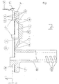
Les dessins annexés montrent à titre d'exemple une forme d'exécution schématisée du dispositif, objet de l'invention.
- La figure 1 est une vue schématique en coupe agrandie selon l'axe A-A' du dispositif mis en place dans l'ouverture pratiquée dans le couvercle d'un récipient.
- La figure 2 est une vue schématique en projection du dispositif de l'invention, vu de dessus.
- La figure 3 est une vue schématique de l'ensemble du dispositif de l'invention et d'un récipient, l'ensemble étant prêt pour l'emploi.
- Figure 1 is a schematic enlarged sectional view along the axis AA 'of the device placed in the opening in the lid of a container.
- Figure 2 is a schematic projection view of the device of the invention, seen from above.
- Figure 3 is a schematic view of the assembly of the device of the invention and a container, the assembly being ready for use.
Sur ces dessins:
- (1 ) représente la base du bouchon.
- (1') la partie de la base (1 ) qui entoure la dépression (2) de la base et qui correspond au plan horizontal de ladite base (1 ).
- (1") la surface de la partie (1') de la base (1), tournée vers le récipient dont le dispositif doit assurer la fermeture.
- (2) la dépression de la base (1).
- (3) les parois de la dépression (2).
- (4) les parties amincies des parois (3).
- (5) le fond de la dépression (2).
- (6) les nervures disposées sur la surface (1 ") de la partie (1') de la base (1 ).
- (7) l'ergot de maintien.
- (8) le bord de l'ouverture du couvercle (9) du récipient (10).
- (11 ) le clip de sécurité.
- (12) le bec d'écoulement.
- (13) le demi-pas de vis auquel se visse un conduit.
- (14) le renforcement du fond (5) de la dépression (2).
- (15) le joint.
- (16) les rangées des nervures (6) disposées sur la surface (1 ") de la partie (1 ') de la base (1 ), destinées à assurer après la fermeture du récipient (10) l'imperméabilité au liquide qui y est contenu et la perméabilité à l'air.
- (1) represents the base of the cap.
- (1 ') the part of the base (1) which surrounds the depression (2) of the base and which corresponds to the horizontal plane of said base (1).
- (1 ") the surface of the part (1 ') of the base (1), facing the container whose device must ensure closure.
- (2) the base depression (1).
- (3) the walls of the depression (2).
- (4) the thinned parts of the walls (3).
- (5) the bottom of the depression (2).
- (6) the ribs arranged on the surface (1 ") of the part (1 ') of the base (1).
- (7) the retaining lug.
- (8) the edge of the opening of the lid (9) of the container (10).
- (11) the safety clip.
- (12) the spout.
- (13) the half pitch of the screw to which a conduit is screwed.
- (14) strengthening the bottom (5) of the depression (2).
- (15) the joint.
- (16) the rows of ribs (6) arranged on the surface (1 ") of the part (1 ') of the base (1), intended to ensure, after the closure of the container (10), impermeability to the liquid which therein is contained and air permeability.
Lors de l'utilisation du dispositif de la présente invention on procède en premier lieu à l'ouverture du récipient (10).When using the device of the present invention, the container (10) is opened first.
Cette ouverture peut se faire par exemple par l'arrachement d'une partie du couvercle (9). Une fois l'ouverture pratiquée dans le récipient (10), on procède à la mise en place du dispositif selon l'invention, préalablement libéré de son conditionnement. Pour le mettre en place, on introduit premièrement le clip de sécurité (11) et les ergots de maintien (7) dans l'ouverture pratiquée, et applique la base (1 ) du dispositif contre le couvercle (9) du récipient (10).This opening can be done for example by tearing off part of the cover (9). Once the opening has been made in the container (10), the device according to the invention is put in place, previously released from its packaging. To set it up, first insert the safety clip (11) and the retaining pins (7) into the opening, and apply the base (1) of the device against the cover (9) of the container (10) .
Il suffit ensuite de faire pression sur le renforcement (14) du fond (5) de la dépression (2), pour que la dépression (2) s'aplatisse et que l'ensemble se déforme.It then suffices to apply pressure to the reinforcement (14) of the bottom (5) of the depression (2), so that the depression (2) becomes flat and the assembly is deformed.
Cette déformation est rendue possible grâce aux parites amincies (4) des parois (3) de la dépression (2).This deformation is made possible by the thinned parities (4) of the walls (3) of the depression (2).
Sous la pression exercée comme indiqué ci- dessus, lors de la déformation de la dépression (2), celle-ci s'aplatit donc jusqu'à ce que son fond (5) vienne se placer au même niveau que le reste de la base (1).Under the pressure exerted as indicated above, during the deformation of the depression (2), it therefore flattens until its bottom (5) comes to be placed at the same level as the rest of the base. (1).
Au cours de cette déformation, les parois (3) se rapprochent du plan horizontal du reste de la base (1). Ce faisant, et comme les parois comportent les ergots de maintien (7), l'orientation de ces derniers se trouve modifiée au fur et à mesure de la déformation de la dépression (2).During this deformation, the walls (3) approach the horizontal plane from the rest of the base (1). In doing so, and as the walls include the retaining lugs (7), the orientation of the latter is changed as the depression (2) is deformed.
En effet, comme les parois (3) s'aplatissent, elles déplacent simultanément les extrémités des sommets des ergots (7) de manière à les faire pivoter sous le couvercle (9) et ainsi à les enclan- cher sous le couvercle (9).Indeed, as the walls (3) flatten, they simultaneously move the ends of the tops of the lugs (7) so as to pivot them under the cover (9) and thus to engage them under the cover (9) .
Les ergots (7) enclenchés sous le couvercle (9), assurent le maintien en place du dispositif de l'invention.The pins (7) engaged under the cover (9), keep the device of the invention in place.
En fait, une fois le dispositif de l'invention mis en place, il est presque impossible en tirant sur le bec d'écoulement (12) de faire revenir le dispositif à sa position initiale, sans faire céder lesdites parois (3) et donc lacher la prise aux ergots de maintien (7).In fact, once the device of the invention in place, it is almost impossible by pulling on the flow spout (12) to return the device to its initial position, without causing said walls (3) and therefore release the plug from the retaining pins (7).
Lors de la mise en plan du dispositif, les rangées (16) des nervures (6) déforment le joint (15) juste suffisament pour garantir le bon contact entre lesdites nervures (6) et ledit joint (15).When the device is planed, the rows (16) of the ribs (6) deform the seal (15) just enough to guarantee good contact between said ribs (6) and said seal (15).
Lors de cette déformation du joint (15), le degré de compression dudit joint (15) n'est pas uniforme sur toute sa surface. En effet, la compression est beaucoup plus grande aux endroits où les nervures (6) compriment ledit joint (15) qu'aux endroits situés entre les nervures (6).During this deformation of the seal (15), the degree of compression of said seal (15) is not united forms over its entire surface. Indeed, the compression is much greater at the places where the ribs (6) compress said seal (15) than at the places located between the ribs (6).
Néanmoins, la compression est suffisament forte pour créer le contact intime entre le joint et la partie (1') de la base (1 ). Ce contact, compte tenu également du fait que lesdites nervures des différentes rangées sont disposées en chicanes les unes par rapport aux autres, empêche le liquide contenu dans le récipient de traverser les chicanes des nervures et de provoquer des fuites, d'autant plus que le dispositif de la présente invention est notamment destiné aux liquides plus ou moins visqueux, comme c'est le cas des préparations nutritives.However, the compression is strong enough to create intimate contact between the joint and the part (1 ') of the base (1). This contact, also taking into account the fact that said ribs of the different rows are arranged in baffles with respect to each other, prevents the liquid contained in the container from passing through the baffles of the ribs and causing leaks, all the more so as the The device of the present invention is in particular intended for more or less viscous liquids, as is the case with nutritive preparations.
Si un tel liquide parvient à s'infiltrer dans la première rangée, les nervures des rangées suivantes étant disposées en chicanes ne lui permettent pas de traverser toutes les rangées.If such a liquid manages to seep into the first row, the ribs of the following rows being arranged in baffles do not allow it to cross all the rows.
En ce qui concerne la perméabilité à l'air du dispositif de l'invention mis en place, le récipient une fois retourné et l'écoulement du liquide du récipient commencé, il se crée à l'intérieur du dispositif une dépression. Cette dépression grandit avec l'écoulement du liquide et fait appel d'air.With regard to the air permeability of the device of the invention installed, the container once turned over and the flow of the liquid from the container started, a vacuum is created inside the device. This depression increases with the flow of liquid and draws in air.
Cette force d'aspiration combinée avec la compression mesurée exercée sur le joint (15) par les rangées (16) des nervures (6), et variable selon les endroits, permet à l'air de traverser le passage pour pénétrer entre lesdites nervures (6) et, en cheminant entre les rangées (16), de pénétrer par l'ouverture du couvercle (9), dans le récipient.This suction force combined with the measured compression exerted on the seal (15) by the rows (16) of the ribs (6), and variable depending on the location, allows air to pass through the passage to penetrate between said ribs ( 6) and, moving between the rows (16), to penetrate through the opening of the cover (9), into the container.
Par la même occasion, l'air aspiré empêche simultanément le liquide de s'infiltrer profondément entre les rangées (16).At the same time, the air drawn in simultaneously prevents the liquid from seeping deeply between the rows (16).
Grâce à l'agencement du dispositif de l'invention, le liquide peut s'écouler du récipient normalement, sans que des fuites se produisent.Thanks to the arrangement of the device of the invention, the liquid can flow from the container normally, without leakage occurring.
Une fois donc le dispositif de l'invention mis en place, on relie le bec d'écoulement (12) à un conduit que l'on visse sur le demi-pas de vis (13) dudit bec d'écoulement (12), puis on retourne le récipient (10) de 180° et suspend l'ensemble à une potence.Once the device of the invention has been put in place, the flow spout (12) is connected to a duct which is screwed onto the half-pitch of the screw (13) of said flow spout (12), then the container (10) is turned over 180 ° and the assembly is suspended from a bracket.
L'écoulement de la préparation nutritive contenue dans le récipient (10) doit s'effectuer dans des conditions de lenteur suffisante pour que le malade ne subisse pas de phénomène d'intolé- rence digestive.The flow of the nutritive preparation contained in the container (10) must be carried out under conditions of sufficient slowness so that the patient does not undergo a phenomenon of digestive intolerance.
A cet effet, le conduit peut être doté d'un système de contrôle de débit, tel qu'un compte- gouttes et d'un système de régulation de vitesse d'écoulement, comme par exemple une pince de Mohr.For this purpose, the conduit can be provided with a flow control system, such as a dropper and with a flow speed regulation system, such as for example a Mohr forceps.
Grâce à la conception du dispositif de l'invention et à l'agencement de ses éléments, l'écoulement du contenu d'un récipient s'effectue dans les conditions recherchées.Thanks to the design of the device of the invention and the arrangement of its elements, the flow of the contents of a container takes place under the desired conditions.
Claims (8)
Applications Claiming Priority (2)
| Application Number | Priority Date | Filing Date | Title |
|---|---|---|---|
| FR8111389A FR2507578A1 (en) | 1981-06-10 | 1981-06-10 | FLOW DEVICE |
| FR8111389 | 1981-06-10 |
Publications (2)
| Publication Number | Publication Date |
|---|---|
| EP0067737A1 EP0067737A1 (en) | 1982-12-22 |
| EP0067737B1 true EP0067737B1 (en) | 1985-09-04 |
Family
ID=9259343
Family Applications (1)
| Application Number | Title | Priority Date | Filing Date |
|---|---|---|---|
| EP82400915A Expired EP0067737B1 (en) | 1981-06-10 | 1982-05-17 | Administering device |
Country Status (5)
| Country | Link |
|---|---|
| EP (1) | EP0067737B1 (en) |
| DE (1) | DE3266002D1 (en) |
| DK (1) | DK156877C (en) |
| FR (1) | FR2507578A1 (en) |
| NO (1) | NO154565C (en) |
Cited By (1)
| Publication number | Priority date | Publication date | Assignee | Title |
|---|---|---|---|---|
| DE3926395C1 (en) * | 1989-08-10 | 1991-03-07 | Fresenius Ag, 6380 Bad Homburg, De | Infusion system for feeding patient - uses two bags held in frame with complementary connection pieces |
Families Citing this family (1)
| Publication number | Priority date | Publication date | Assignee | Title |
|---|---|---|---|---|
| SE441978B (en) * | 1981-09-23 | 1985-11-25 | Goran Per Erik Sjonell | DROP PACKAGING CONNECTOR |
Family Cites Families (5)
| Publication number | Priority date | Publication date | Assignee | Title |
|---|---|---|---|---|
| US2844289A (en) * | 1956-06-01 | 1958-07-22 | Sherwin Williams Co | Adaptor for nozzle, spout, coupler, or the like |
| CH409670A (en) * | 1964-06-05 | 1966-03-15 | Hoffmann Ag Geb | Spout on a container |
| FR2422569A1 (en) * | 1978-04-14 | 1979-11-09 | Roussel Uclaf | STERILE LIQUID DISPENSER |
| NL171960C (en) * | 1978-04-18 | 1983-06-16 | Sterimed Gmbh | VACUUM BOTTLE FOR EXTRACTING SEPARATIONS FROM WOUND CAVES. |
| US4235344A (en) * | 1979-01-29 | 1980-11-25 | Baxter Travenol Laboratories, Inc. | Irrigation cap |
-
1981
- 1981-06-10 FR FR8111389A patent/FR2507578A1/en active Granted
-
1982
- 1982-05-17 EP EP82400915A patent/EP0067737B1/en not_active Expired
- 1982-05-17 DE DE8282400915T patent/DE3266002D1/en not_active Expired
- 1982-06-09 DK DK257582A patent/DK156877C/en active
- 1982-06-09 NO NO821923A patent/NO154565C/en unknown
Cited By (1)
| Publication number | Priority date | Publication date | Assignee | Title |
|---|---|---|---|---|
| DE3926395C1 (en) * | 1989-08-10 | 1991-03-07 | Fresenius Ag, 6380 Bad Homburg, De | Infusion system for feeding patient - uses two bags held in frame with complementary connection pieces |
Also Published As
| Publication number | Publication date |
|---|---|
| FR2507578B1 (en) | 1983-11-18 |
| FR2507578A1 (en) | 1982-12-17 |
| NO154565B (en) | 1986-07-14 |
| NO154565C (en) | 1986-10-22 |
| DK156877C (en) | 1990-04-09 |
| NO821923L (en) | 1982-12-13 |
| DE3266002D1 (en) | 1985-10-10 |
| EP0067737A1 (en) | 1982-12-22 |
| DK156877B (en) | 1989-10-16 |
| DK257582A (en) | 1982-12-11 |
Similar Documents
| Publication | Publication Date | Title |
|---|---|---|
| EP0410858B1 (en) | Assembly for dispensing at least one fluid product such as cosmetics or pharmaceutics | |
| EP0655045B1 (en) | Multiple compartment dispenser for storing and blending of contents | |
| EP0410857B1 (en) | Assembly for dispensing at least one product, especially cosmetics, in cream, fluid or powder form | |
| EP0242253B1 (en) | Disposable dispenser pump for liquid and pasty products | |
| EP0538162B1 (en) | Sealing means for containers | |
| FR2836129A1 (en) | Connector between receptacle and container e.g. for mixing medical compound has cap covering sleeve or piston made with projection engaging with skirt | |
| FR2859118A1 (en) | DISPOSABLE BUCKET TO BE MOUNTED ON A GUN FOR THE PREPARATION, APPLICATION AND PRESERVATION OF A PAINT | |
| LU84334A1 (en) | DEVICE FOR PROVIDING STERILE SOLUTION AND ITS REPLACEMENT WITH AIR | |
| FR2726992A1 (en) | DEVICE FOR THE SAMPLING AND ANALYSIS OF BIOLOGICAL LIQUIDS | |
| FR2780878A1 (en) | Clip-on cap e.g. for medication in powder form being transferred to solute pouch | |
| EP0999817A1 (en) | Device for dividing a baby feeding bottle into sections | |
| EP0636549B1 (en) | Assembly for dispensing a liquid or pasty product without air suction, with a deformable membrane | |
| FR2915487A1 (en) | ASSEMBLY AND METHOD FOR MICROBIOLOGICAL ANALYSIS | |
| EP2085068B1 (en) | Liquid-dispensing nozzle and liquid packaging and dispensing system comprising such a nozzle | |
| FR2634460A1 (en) | STOPPER | |
| EP0067737B1 (en) | Administering device | |
| FR2486501A1 (en) | AUTOMATIC CLOSURE SHUTTER PERFECTIONED | |
| FR2785878A1 (en) | Seal assembly for fluid distribution head comprises elastic element shaped as cup with hole that is covered by fixed cylinder and deforms under effect of product distribution pressure. | |
| FR2605293A1 (en) | Stopper equipped with a gas release valve | |
| WO1985001193A1 (en) | Device for cleaning and storing hydrophilic contact lenses by the use of appropriate solutions | |
| EP0934887A1 (en) | Closure device for a beverage can, especially for carbonated beverages | |
| EP1785126B1 (en) | Nursing bottle with a lateral device for controlling the inlet of air | |
| EP0328427B1 (en) | Unit for the sealed storage and direct and controlled application of a fluid to a support | |
| FR2694492A1 (en) | Droplet applicator esp for medicinal liquids used in ophthalmology - has calibrated outlet and piston to expel droplets through it when container is compressed | |
| EP1557371B1 (en) | Kit comprising two containers and an applicator |
Legal Events
| Date | Code | Title | Description |
|---|---|---|---|
| PUAI | Public reference made under article 153(3) epc to a published international application that has entered the european phase |
Free format text: ORIGINAL CODE: 0009012 |
|
| AK | Designated contracting states |
Designated state(s): BE CH DE GB IT LI NL SE |
|
| 17P | Request for examination filed |
Effective date: 19830223 |
|
| ITF | It: translation for a ep patent filed |
Owner name: BARZANO' E ZANARDO ROMA S.P.A. |
|
| GRAA | (expected) grant |
Free format text: ORIGINAL CODE: 0009210 |
|
| AK | Designated contracting states |
Designated state(s): BE CH DE GB IT LI NL SE |
|
| REF | Corresponds to: |
Ref document number: 3266002 Country of ref document: DE Date of ref document: 19851010 |
|
| PLBE | No opposition filed within time limit |
Free format text: ORIGINAL CODE: 0009261 |
|
| STAA | Information on the status of an ep patent application or granted ep patent |
Free format text: STATUS: NO OPPOSITION FILED WITHIN TIME LIMIT |
|
| 26N | No opposition filed | ||
| ITTA | It: last paid annual fee | ||
| REG | Reference to a national code |
Ref country code: CH Ref legal event code: PUE Owner name: CLINTEC NUTRITION COMPANY |
|
| ITPR | It: changes in ownership of a european patent |
Owner name: CESSIONE;CLINTEC NUTRITION COMPANY |
|
| NLS | Nl: assignments of ep-patents |
Owner name: CLINTEC NUTRITION COMPANY TE DEERFIELD, ILLINOIS, |
|
| EAL | Se: european patent in force in sweden |
Ref document number: 82400915.3 |
|
| PGFP | Annual fee paid to national office [announced via postgrant information from national office to epo] |
Ref country code: GB Payment date: 19970508 Year of fee payment: 16 |
|
| PGFP | Annual fee paid to national office [announced via postgrant information from national office to epo] |
Ref country code: SE Payment date: 19970516 Year of fee payment: 16 |
|
| PGFP | Annual fee paid to national office [announced via postgrant information from national office to epo] |
Ref country code: DE Payment date: 19970523 Year of fee payment: 16 |
|
| PGFP | Annual fee paid to national office [announced via postgrant information from national office to epo] |
Ref country code: NL Payment date: 19970529 Year of fee payment: 16 |
|
| PGFP | Annual fee paid to national office [announced via postgrant information from national office to epo] |
Ref country code: CH Payment date: 19970610 Year of fee payment: 16 |
|
| PGFP | Annual fee paid to national office [announced via postgrant information from national office to epo] |
Ref country code: BE Payment date: 19970711 Year of fee payment: 16 |
|
| PG25 | Lapsed in a contracting state [announced via postgrant information from national office to epo] |
Ref country code: GB Free format text: LAPSE BECAUSE OF NON-PAYMENT OF DUE FEES Effective date: 19980517 |
|
| PG25 | Lapsed in a contracting state [announced via postgrant information from national office to epo] |
Ref country code: SE Free format text: LAPSE BECAUSE OF NON-PAYMENT OF DUE FEES Effective date: 19980518 |
|
| PG25 | Lapsed in a contracting state [announced via postgrant information from national office to epo] |
Ref country code: LI Free format text: LAPSE BECAUSE OF NON-PAYMENT OF DUE FEES Effective date: 19980531 Ref country code: CH Free format text: LAPSE BECAUSE OF NON-PAYMENT OF DUE FEES Effective date: 19980531 Ref country code: BE Free format text: LAPSE BECAUSE OF NON-PAYMENT OF DUE FEES Effective date: 19980531 |
|
| NLS | Nl: assignments of ep-patents |
Owner name: SOCIETE DES PRODUITS NESTLE SA |
|
| BERE | Be: lapsed |
Owner name: SOC. DES PRODUITS NESTLE S.A. Effective date: 19980531 |
|
| PG25 | Lapsed in a contracting state [announced via postgrant information from national office to epo] |
Ref country code: NL Free format text: LAPSE BECAUSE OF NON-PAYMENT OF DUE FEES Effective date: 19981201 |
|
| BECA | Be: change of holder's address |
Free format text: 980709 SOC. DES PRODUITS *NESTLE S.A.:CASE POSTALE 353, 1800 VEVEY |
|
| GBPC | Gb: european patent ceased through non-payment of renewal fee |
Effective date: 19980517 |
|
| REG | Reference to a national code |
Ref country code: CH Ref legal event code: PL |
|
| EUG | Se: european patent has lapsed |
Ref document number: 82400915.3 |
|
| NLV4 | Nl: lapsed or anulled due to non-payment of the annual fee |
Effective date: 19981201 |
|
| PG25 | Lapsed in a contracting state [announced via postgrant information from national office to epo] |
Ref country code: DE Free format text: LAPSE BECAUSE OF NON-PAYMENT OF DUE FEES Effective date: 19990302 |