EP0066740B1 - Dispositif de fabrication de câbles plats - Google Patents
Dispositif de fabrication de câbles plats Download PDFInfo
- Publication number
- EP0066740B1 EP0066740B1 EP82104334A EP82104334A EP0066740B1 EP 0066740 B1 EP0066740 B1 EP 0066740B1 EP 82104334 A EP82104334 A EP 82104334A EP 82104334 A EP82104334 A EP 82104334A EP 0066740 B1 EP0066740 B1 EP 0066740B1
- Authority
- EP
- European Patent Office
- Prior art keywords
- extrusion
- wires
- heads
- sheet
- plastic material
- Prior art date
- Legal status (The legal status is an assumption and is not a legal conclusion. Google has not performed a legal analysis and makes no representation as to the accuracy of the status listed.)
- Expired
Links
- 238000004519 manufacturing process Methods 0.000 title claims description 23
- 238000001125 extrusion Methods 0.000 claims description 48
- 229920003023 plastic Polymers 0.000 claims description 36
- 239000004033 plastic Substances 0.000 claims description 36
- 239000000463 material Substances 0.000 claims description 27
- 238000011144 upstream manufacturing Methods 0.000 claims description 5
- 239000002184 metal Substances 0.000 claims description 3
- 229910052751 metal Inorganic materials 0.000 claims description 3
- 238000003490 calendering Methods 0.000 description 15
- 239000004020 conductor Substances 0.000 description 13
- 230000009471 action Effects 0.000 description 7
- 239000000203 mixture Substances 0.000 description 6
- 238000009826 distribution Methods 0.000 description 5
- 229920001774 Perfluoroether Polymers 0.000 description 4
- 230000000712 assembly Effects 0.000 description 4
- 238000000429 assembly Methods 0.000 description 4
- 238000012423 maintenance Methods 0.000 description 4
- 239000004800 polyvinyl chloride Substances 0.000 description 4
- -1 polyéthylène Polymers 0.000 description 4
- 229920001780 ECTFE Polymers 0.000 description 3
- VGGSQFUCUMXWEO-UHFFFAOYSA-N Ethene Chemical compound C=C VGGSQFUCUMXWEO-UHFFFAOYSA-N 0.000 description 3
- 239000004952 Polyamide Substances 0.000 description 3
- 229920002647 polyamide Polymers 0.000 description 3
- 229920000915 polyvinyl chloride Polymers 0.000 description 3
- 238000000926 separation method Methods 0.000 description 3
- 238000003466 welding Methods 0.000 description 3
- 229910000906 Bronze Inorganic materials 0.000 description 2
- 239000010974 bronze Substances 0.000 description 2
- 239000011248 coating agent Substances 0.000 description 2
- 238000000576 coating method Methods 0.000 description 2
- 210000001520 comb Anatomy 0.000 description 2
- 238000001816 cooling Methods 0.000 description 2
- KUNSUQLRTQLHQQ-UHFFFAOYSA-N copper tin Chemical compound [Cu].[Sn] KUNSUQLRTQLHQQ-UHFFFAOYSA-N 0.000 description 2
- 238000006073 displacement reaction Methods 0.000 description 2
- 238000010438 heat treatment Methods 0.000 description 2
- 229920001343 polytetrafluoroethylene Polymers 0.000 description 2
- 239000004810 polytetrafluoroethylene Substances 0.000 description 2
- 229920002635 polyurethane Polymers 0.000 description 2
- 239000004814 polyurethane Substances 0.000 description 2
- 229920001169 thermoplastic Polymers 0.000 description 2
- 239000012815 thermoplastic material Substances 0.000 description 2
- 239000004416 thermosoftening plastic Substances 0.000 description 2
- 230000003313 weakening effect Effects 0.000 description 2
- CHJAYYWUZLWNSQ-UHFFFAOYSA-N 1-chloro-1,2,2-trifluoroethene;ethene Chemical group C=C.FC(F)=C(F)Cl CHJAYYWUZLWNSQ-UHFFFAOYSA-N 0.000 description 1
- 239000005995 Aluminium silicate Substances 0.000 description 1
- 208000031968 Cadaver Diseases 0.000 description 1
- RYGMFSIKBFXOCR-UHFFFAOYSA-N Copper Chemical compound [Cu] RYGMFSIKBFXOCR-UHFFFAOYSA-N 0.000 description 1
- 208000018672 Dilatation Diseases 0.000 description 1
- 239000005977 Ethylene Substances 0.000 description 1
- 239000004698 Polyethylene Substances 0.000 description 1
- 241000135309 Processus Species 0.000 description 1
- 229910000831 Steel Inorganic materials 0.000 description 1
- 241001080024 Telles Species 0.000 description 1
- XTXRWKRVRITETP-UHFFFAOYSA-N Vinyl acetate Chemical compound CC(=O)OC=C XTXRWKRVRITETP-UHFFFAOYSA-N 0.000 description 1
- 240000008042 Zea mays Species 0.000 description 1
- 239000000853 adhesive Substances 0.000 description 1
- 230000001070 adhesive effect Effects 0.000 description 1
- 235000012211 aluminium silicate Nutrition 0.000 description 1
- 230000005540 biological transmission Effects 0.000 description 1
- 230000008859 change Effects 0.000 description 1
- UUAGAQFQZIEFAH-UHFFFAOYSA-N chlorotrifluoroethylene Chemical compound FC(F)=C(F)Cl UUAGAQFQZIEFAH-UHFFFAOYSA-N 0.000 description 1
- 238000005056 compaction Methods 0.000 description 1
- 229910052802 copper Inorganic materials 0.000 description 1
- 239000010949 copper Substances 0.000 description 1
- 230000006866 deterioration Effects 0.000 description 1
- 229920001971 elastomer Polymers 0.000 description 1
- 239000000806 elastomer Substances 0.000 description 1
- 239000012467 final product Substances 0.000 description 1
- 239000012530 fluid Substances 0.000 description 1
- 238000009413 insulation Methods 0.000 description 1
- 239000013067 intermediate product Substances 0.000 description 1
- 238000005304 joining Methods 0.000 description 1
- NLYAJNPCOHFWQQ-UHFFFAOYSA-N kaolin Chemical compound O.O.O=[Al]O[Si](=O)O[Si](=O)O[Al]=O NLYAJNPCOHFWQQ-UHFFFAOYSA-N 0.000 description 1
- 238000000034 method Methods 0.000 description 1
- 239000013307 optical fiber Substances 0.000 description 1
- 238000005457 optimization Methods 0.000 description 1
- 235000011837 pasties Nutrition 0.000 description 1
- 239000008029 phthalate plasticizer Substances 0.000 description 1
- 238000007747 plating Methods 0.000 description 1
- 229920000573 polyethylene Polymers 0.000 description 1
- 229920000098 polyolefin Polymers 0.000 description 1
- 238000002360 preparation method Methods 0.000 description 1
- 230000009467 reduction Effects 0.000 description 1
- 238000003303 reheating Methods 0.000 description 1
- 239000000523 sample Substances 0.000 description 1
- 238000007493 shaping process Methods 0.000 description 1
- 238000010008 shearing Methods 0.000 description 1
- 239000010959 steel Substances 0.000 description 1
- 238000003860 storage Methods 0.000 description 1
- 229920001187 thermosetting polymer Polymers 0.000 description 1
- 230000000007 visual effect Effects 0.000 description 1
- 239000002699 waste material Substances 0.000 description 1
Images


Classifications
-
- H—ELECTRICITY
- H01—ELECTRIC ELEMENTS
- H01B—CABLES; CONDUCTORS; INSULATORS; SELECTION OF MATERIALS FOR THEIR CONDUCTIVE, INSULATING OR DIELECTRIC PROPERTIES
- H01B7/00—Insulated conductors or cables characterised by their form
- H01B7/08—Flat or ribbon cables
- H01B7/0838—Parallel wires, sandwiched between two insulating layers
-
- B—PERFORMING OPERATIONS; TRANSPORTING
- B29—WORKING OF PLASTICS; WORKING OF SUBSTANCES IN A PLASTIC STATE IN GENERAL
- B29C—SHAPING OR JOINING OF PLASTICS; SHAPING OF MATERIAL IN A PLASTIC STATE, NOT OTHERWISE PROVIDED FOR; AFTER-TREATMENT OF THE SHAPED PRODUCTS, e.g. REPAIRING
- B29C48/00—Extrusion moulding, i.e. expressing the moulding material through a die or nozzle which imparts the desired form; Apparatus therefor
- B29C48/001—Combinations of extrusion moulding with other shaping operations
- B29C48/0013—Extrusion moulding in several steps, i.e. components merging outside the die
- B29C48/0014—Extrusion moulding in several steps, i.e. components merging outside the die producing flat articles having components brought in contact outside the extrusion die
-
- B—PERFORMING OPERATIONS; TRANSPORTING
- B29—WORKING OF PLASTICS; WORKING OF SUBSTANCES IN A PLASTIC STATE IN GENERAL
- B29C—SHAPING OR JOINING OF PLASTICS; SHAPING OF MATERIAL IN A PLASTIC STATE, NOT OTHERWISE PROVIDED FOR; AFTER-TREATMENT OF THE SHAPED PRODUCTS, e.g. REPAIRING
- B29C48/00—Extrusion moulding, i.e. expressing the moulding material through a die or nozzle which imparts the desired form; Apparatus therefor
- B29C48/16—Articles comprising two or more components, e.g. co-extruded layers
- B29C48/18—Articles comprising two or more components, e.g. co-extruded layers the components being layers
- B29C48/21—Articles comprising two or more components, e.g. co-extruded layers the components being layers the layers being joined at their surfaces
-
- H—ELECTRICITY
- H01—ELECTRIC ELEMENTS
- H01B—CABLES; CONDUCTORS; INSULATORS; SELECTION OF MATERIALS FOR THEIR CONDUCTIVE, INSULATING OR DIELECTRIC PROPERTIES
- H01B13/00—Apparatus or processes specially adapted for manufacturing conductors or cables
- H01B13/06—Insulating conductors or cables
- H01B13/14—Insulating conductors or cables by extrusion
- H01B13/143—Insulating conductors or cables by extrusion with a special opening of the extrusion head
- H01B13/144—Heads for simultaneous extrusion on two or more conductors
-
- B—PERFORMING OPERATIONS; TRANSPORTING
- B29—WORKING OF PLASTICS; WORKING OF SUBSTANCES IN A PLASTIC STATE IN GENERAL
- B29C—SHAPING OR JOINING OF PLASTICS; SHAPING OF MATERIAL IN A PLASTIC STATE, NOT OTHERWISE PROVIDED FOR; AFTER-TREATMENT OF THE SHAPED PRODUCTS, e.g. REPAIRING
- B29C48/00—Extrusion moulding, i.e. expressing the moulding material through a die or nozzle which imparts the desired form; Apparatus therefor
- B29C48/03—Extrusion moulding, i.e. expressing the moulding material through a die or nozzle which imparts the desired form; Apparatus therefor characterised by the shape of the extruded material at extrusion
- B29C48/07—Flat, e.g. panels
- B29C48/08—Flat, e.g. panels flexible, e.g. films
Definitions
- the invention relates to a device for manufacturing flat cables. It applies in particular to the manufacture of electric cables comprising a large number of metallic conductors insulated from each other.
- Document FR-A-2 086 267 discloses a device according to the preamble of claim 1, which provides a flat cable from a web of wires and a extruder, which creates a layer of plastic material. on either side of this tablecloth. These two layers are applied against the sheet using two stationary rollers, which are provided to guide and deflect the flows of the molten mixture. In the absence of precise guidance of the wires of the sheet near the point where the two layers are applied to the sheet, it seems impossible to manufacture by this method a flat cable whose conductors are sufficiently close to each other to avoid excessive cable width, without however contacting each other directly.
- Document CH-A-492543 also discloses a device for the manufacture of a thermoplastic tape, which is reinforced with longitudinal wires.
- the layer of wires is guided by two combs arranged upstream of the extrusion assembly. These combs are not capable of maintaining the correct positioning of the wires until the plastic material has cooled. Moreover, this does not constitute a major drawback when the wires are used to arm a thermoplastic tape and not for the transmission of electrical signals.
- the invention aims to provide a device according to the preamble of the main claim, which ensures very precise positioning of the son of the web during the extrusion of the plastic, which allows to pass the assembly consisting of the layer of wires and the two layers of plastic material between two calendered rollers with grooved profile in correspondence with the positioning of the wires of the layer.
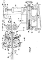
- FIG. 1 represents a view of the extrusion and calendering assemblies of this device in section through a median longitudinal vertical plane, that is to say passing through the median line of the ply of wires which constitutes the cores of the cable manufactured .
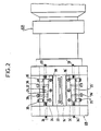
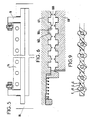
- Figures 2, 3, 4 and 5 show partial views of this device in section through planes II-II, IIl-III, IV-IV, VV of Figure 1, respectively these planes being transverse vertical that is - say perpendicular to the wires, the scale being enlarged in FIG. 5.
- FIG. 6 represents a detail on an enlarged scale of FIG. 4.
- Figures 7 and 8 show views of the assembly of the same device according to the invention, respectively in side view and from above.
- Figure 9 shows a cross section. of a flat cable according to the invention.
- a device in accordance with FIG. 1, comprises an extrusion assembly G9 itself comprising two superimposed extrusion heads, an upper head 21 and a lower head 21 ', supplied with hot plastic material by a extruder G21 ( see Figure 3) whose axis is horizontal transverse, that is to say perpendicular to the plane of Figure 1.
- a guide assembly G6 guides a horizontal sheet 12 of parallel copper wires which advance in the direction of their lengths in passing between the two heads 21 and 21 '.
- the words “downstream" upstream will be employed below with reference to the moving direction of the son, the direction of the son being called “longitudinal • and the horizontal direction perpendicular being called" cross p.
- Each of these heads provides a strip of hot plastic material 23 above and 23 ′ below the layer of wires 12, the assembly then passing between the rollers 67 and 68 of a calendering assembly G10.
- the axes of these rollers are horizontal transverse.
- the guide assembly G6 comprises a frame 18 disposed upstream of the two extrusion heads and carrying a cantilevered beam 11 which extends downstream, passes in the interval between these two heads without. touch them, and carries at its end downstream of these heads a thread guide 14 which individually guides each of the threads of the ply 12.
- the calender rollers are free to move in the vertical direction. On the other hand, they are kept perfectly aligned in the transverse direction.
- the stop 61 prevents them from colliding with one another.
- the wire guide loaded with wires is advanced.
- the wires are conventionally hooked to a pulling rope itself driven by the track G15 of the line (that is to say between drive bands G15a and G15b located on the production line downstream of the assembly calendering, according to Figures 7 and 8).
- the bringing together of the rollers achieves the profiling of the plastic material under the action of the counterweight 74 which precisely defines the pressure applied by the rollers to the strips of plastic material.
- the absence of positioning stops in the vertical direction allows the rollers to automatically adjust according to variations in the flow rate of the extrusion heads, that is to say the thickness of the extruded bands, and makes it possible to absorb all thickness variations without affecting the distance between the conductors.
- the two calendering rollers 67 and 68 are identical. They each comprise circular grooves 102 which follow one another along the length of the roller and separated by circular grooves in relief 104, the grooves of one roller being opposite those of the other. Each of the grooves 104 carries a weakening net 106 projecting over the entire perimeter of its central circle.
- grooves form on the hot plastic sheaths in relief B coating the wires F (see FIG. 9) and the grooves form flat connecting strips of lesser thickness joining the sheaths.
- the weakening nets they form grooves in the plastic S allowing easy tearing of the finished cable between two conductive wires coated by their sheaths.
- rollers could of course be produced without grooves or grooves if one wanted to manufacture a flat cable with a smooth face.
- a “creel ⁇ Gi (coil support frame) (see FIGS. 7 and 8) carries sixty coils G2 supplying the wires G3 to be coated which are guided towards the guide assembly G6 (FIG. 1). These wires pass through the extrusion assembly G9 comprising the extruder G21 supplied with plastic material by a group G5 then in the calendering assembly G10. These wires coated in the plastic material then constitute the flat cable 76 and they pass successively (see FIG. 7) through the following elements: an air cooling gutter G12 in which they are supported by rollers G13, a cooling tank G14, a light box G4 , a marking device G11, the pulling track G15 in which the cable 76 is clamped between the strips. flexible G15a and G15b, and a G18 control device preceding a G20 reel.
- the following values can be given for the manufacture of a cable in accordance with FIG. 9 and consisting of sixty electric conductor wires with seven strands of 0.13 mm in diameter forming a strand of 0.39 mm regularly spaced 1.27 mm and coated in a 0.4 mm thick sheath and made of polyvinyl chloride loaded with kaolin at 2.5% by weight with 34% of a phthalate plasticizer.
- the number of conductive wires can reach 100 with diameters between 0.16 and 6 mm. These conductors are multifilament if their diameter exceeds 0.8 mm.
- the pitch of these conductive wires can be between 0.4 and 60 mm, with an edge (extreme lateral part of the sheath) equal to at least half of this pitch.
- the total width of the cable can reach 65 mm.
- the presence of grooves S allows subsequent separation of the cable into several cables of smaller widths, by simple manual or mechanical tearing. It is also easy to choose a thickness sufficiently small for the sheath to allow electrical contacts to be made by perforating the sheath by the pins of the insulation displacement connectors.
- the ratio of the width of the cable to its thickness can be greater than 100.
- the coated wires according to the invention may already each have a first individual insulating sheath, and be asymmetrically coated. These wires can be of different types in the same cable. It should be understood that the word wire used here designates all kinds of flexible linear elements capable of being coated in an extrudable material. These "wires can be not only electrical conductors, but also optical fibers, mechanical steel traction wires, pipes for transporting a fluid, etc.
- the sheath may include a central zone without wires so as to allow its fixing, in particular by stapling.
- rollers 67, 68 are normally made of bronze. However, in the case of hot tacky plastics such as polyurethanes and polyamides, the rollers can be coated with a material which is not very adhesive, for example polytetrafluoroethylene (PTFE).
- PTFE polytetrafluoroethylene
- the longitudinal distance between the extrusion slots on the one hand and the interval between the calender rollers 67, 68 on the other hand is between 75 and 150 mm, the distance between these two slots being between 33% and 66% of this longitudinal distance.
- the present invention has many advantages.
- sheaths of different thicknesses are obtained by simple adjustment of the extrusion slots.
- the final profile of the cable is obtained by approximation / welding and calendering of plastic material in the pasty phase. Obtaining a complex profile therefore only requires the execution of simple revolution parts comprising a series of grooves and grooves.
- the duration is less than five minutes.
- the wire guide assembly is independent thanks to the complete physical separation of the three guide, extrusion and calendering assemblies, which makes it possible to adjust the position of the wire guide easily without fear of subsequent adjustment.
- the non-specific wire guide allows all combinations of composition without changing the device from 0 to 100 conductors.
- the separation of the three sets allows the action on each of them without interference on the other two, which allows an optimization of each characteristic.
- the heads produce strips of width always the same independent of the final product to be obtained.
Landscapes
- Engineering & Computer Science (AREA)
- Mechanical Engineering (AREA)
- Manufacturing & Machinery (AREA)
- Extrusion Moulding Of Plastics Or The Like (AREA)
- Insulated Conductors (AREA)
Applications Claiming Priority (2)
| Application Number | Priority Date | Filing Date | Title |
|---|---|---|---|
| FR8110216 | 1981-05-22 | ||
| FR8110216A FR2506500A1 (fr) | 1981-05-22 | 1981-05-22 | Dispositif de fabrication de cables plats |
Publications (2)
| Publication Number | Publication Date |
|---|---|
| EP0066740A1 EP0066740A1 (fr) | 1982-12-15 |
| EP0066740B1 true EP0066740B1 (fr) | 1986-07-30 |
Family
ID=9258778
Family Applications (1)
| Application Number | Title | Priority Date | Filing Date |
|---|---|---|---|
| EP82104334A Expired EP0066740B1 (fr) | 1981-05-22 | 1982-05-18 | Dispositif de fabrication de câbles plats |
Country Status (3)
| Country | Link |
|---|---|
| EP (1) | EP0066740B1 (OSRAM) |
| DE (1) | DE3272292D1 (OSRAM) |
| FR (1) | FR2506500A1 (OSRAM) |
Cited By (1)
| Publication number | Priority date | Publication date | Assignee | Title |
|---|---|---|---|---|
| US6954983B2 (en) | 2000-11-20 | 2005-10-18 | Reifenhäuser GmbH & Co Maschinenfabrik | Method for producing flat cables |
Families Citing this family (6)
| Publication number | Priority date | Publication date | Assignee | Title |
|---|---|---|---|---|
| JPH0197309A (ja) * | 1987-10-09 | 1989-04-14 | Junkosha Co Ltd | フラットケーブル |
| GB9706514D0 (en) * | 1997-04-01 | 1997-05-21 | Skit Scotland Limited | Apparatus for manufacturing ribbon cables |
| AT502813B1 (de) * | 2006-02-14 | 2007-06-15 | I & T Innovation Tech Entw | Verfahren und vorrichtung zum herstellen eines flachkabels |
| CN106098256A (zh) * | 2016-08-08 | 2016-11-09 | 安庆市汇东机械有限责任公司 | 三层共挤交联电缆生产线 |
| CN112917861A (zh) * | 2019-12-05 | 2021-06-08 | 安徽联嘉祥特种电缆有限公司 | 一种用于电缆双线挤出的挤出装置和方法 |
| CN120388807B (zh) * | 2025-06-27 | 2025-11-25 | 广东中联电缆集团有限公司 | 多芯电缆挤出成型模具、生产设备及生产方法 |
Family Cites Families (4)
| Publication number | Priority date | Publication date | Assignee | Title |
|---|---|---|---|---|
| GB815573A (en) * | 1955-09-02 | 1959-07-01 | Sumitomo Electric Industries | Improvements in and relating to insulated electric conductors |
| CH492543A (de) * | 1969-06-25 | 1970-06-30 | Chemica Ag | Verfahren und Einrichtung zur Herstellung verstärkter thermoplastischer Rohre |
| DE2019629C3 (de) * | 1970-04-23 | 1975-01-09 | Ibm Deutschland Gmbh, 7000 Stuttgart | Spritzkopf für Schneckenstrangpressen zum Umhüllen von Bandkabel |
| US3754847A (en) * | 1970-07-23 | 1973-08-28 | Ikegai Iron Works Ltd | Flat die for extruding laminated synthetic resin sheets |
-
1981
- 1981-05-22 FR FR8110216A patent/FR2506500A1/fr active Granted
-
1982
- 1982-05-18 DE DE8282104334T patent/DE3272292D1/de not_active Expired
- 1982-05-18 EP EP82104334A patent/EP0066740B1/fr not_active Expired
Cited By (1)
| Publication number | Priority date | Publication date | Assignee | Title |
|---|---|---|---|---|
| US6954983B2 (en) | 2000-11-20 | 2005-10-18 | Reifenhäuser GmbH & Co Maschinenfabrik | Method for producing flat cables |
Also Published As
| Publication number | Publication date |
|---|---|
| FR2506500B1 (OSRAM) | 1984-01-13 |
| DE3272292D1 (en) | 1986-09-04 |
| EP0066740A1 (fr) | 1982-12-15 |
| FR2506500A1 (fr) | 1982-11-26 |
Similar Documents
| Publication | Publication Date | Title |
|---|---|---|
| EP1276602B1 (fr) | Element de menuiserie extrude renforce par des fibres continues, procede et dispositif | |
| EP0287427B1 (fr) | Procédé de fabrication de profilés de résine thermoplastique renforcés de fibres continues, appareillage pour leur obtention | |
| EP0204607B1 (fr) | Poteau en matière plastique pour supporter notamment des lignes électriques et dispositif pour réaliser un enroulement de fibres sur ce poteau | |
| DE69418526T2 (de) | Verfahren und Vorrichtung zur Herstellung einer drahtverstärkten, gummierten Bahn | |
| EP1123194A1 (fr) | Corps de revolution creux et son procede de fabrication | |
| EP0066740B1 (fr) | Dispositif de fabrication de câbles plats | |
| EP1831454A2 (de) | Flexibles zugorgan | |
| FR2807966A1 (fr) | Procede et dispositif de fabrication d'un profile composite forme de matiere organique thermoplastique renforcee par des fibres de renforcement | |
| EP1697109B1 (de) | Verfahren und vorrichtung zum aufbringen einer verstärkung auf ein kunststoffrohr durch ein wickelschweissverfahren | |
| JP6607237B2 (ja) | ゴム被覆撚線コードの製造方法および装置 | |
| CN112053804A (zh) | 一种防水芯线自动化作业且一体成型的方法 | |
| EP2616231B1 (fr) | Procede de fabrication d'un ressort de suspension en materiau composite de mise en oeuvre simplifiee | |
| EP1695815A1 (fr) | Dispositif et procédé de fabrication de nappes ondulées | |
| EP0326460B1 (fr) | Procédé et installation de fabrication d'un ruban constitué d'au moins un fil imprégné d'un polymère thermoplastique | |
| FR2513003A1 (fr) | Dispositif de fabrication de cables plats avec guide-fils | |
| BE1008711A3 (fr) | Moyens et procede d'application d'une couche de finition de matiere plastique a la surface d'un article composite; article composite revetu. | |
| EP0108016B1 (fr) | Procédé et installation de revêtement de câbles textiles | |
| EP3272507B1 (fr) | Procédé d'obtention d'une pièce profilée courbe en matière composite et/ou synthétique, et dispositif de mise en oeuvre de ce procédé | |
| EP3230513B1 (fr) | Armature textile pour pultrusion et son procede de realisation | |
| EP1429905B1 (de) | Ummantelung von leiterbahnen | |
| IL29220A (en) | Process for preparing a strip of plastic material and a strip prepared thereby | |
| FR2850368A1 (fr) | Procede de depose sur un support de couches fibreuses successives inclinees, a partir d'une bande continue | |
| EP0395676A1 (en) | Process for producing reinforced thermoplastic sheets and related apparatus | |
| DE10213736C1 (de) | Verfahren und Vorrichtung zur Herstellung von Flachbandkabeln | |
| DE3785310T2 (de) | Methode zur vermeidung von durch ausdehnung bewirkten falten in kunststoffilmen und metallfolien. |
Legal Events
| Date | Code | Title | Description |
|---|---|---|---|
| PUAI | Public reference made under article 153(3) epc to a published international application that has entered the european phase |
Free format text: ORIGINAL CODE: 0009012 |
|
| AK | Designated contracting states |
Designated state(s): BE CH DE FR GB IT LI LU NL |
|
| 17P | Request for examination filed |
Effective date: 19830530 |
|
| GRAA | (expected) grant |
Free format text: ORIGINAL CODE: 0009210 |
|
| AK | Designated contracting states |
Kind code of ref document: B1 Designated state(s): BE CH DE FR GB IT LI LU NL |
|
| REF | Corresponds to: |
Ref document number: 3272292 Country of ref document: DE Date of ref document: 19860904 |
|
| ITF | It: translation for a ep patent filed | ||
| PLBE | No opposition filed within time limit |
Free format text: ORIGINAL CODE: 0009261 |
|
| STAA | Information on the status of an ep patent application or granted ep patent |
Free format text: STATUS: NO OPPOSITION FILED WITHIN TIME LIMIT |
|
| 26N | No opposition filed | ||
| PGFP | Annual fee paid to national office [announced via postgrant information from national office to epo] |
Ref country code: GB Payment date: 19910424 Year of fee payment: 10 |
|
| PGFP | Annual fee paid to national office [announced via postgrant information from national office to epo] |
Ref country code: CH Payment date: 19910523 Year of fee payment: 10 |
|
| PGFP | Annual fee paid to national office [announced via postgrant information from national office to epo] |
Ref country code: FR Payment date: 19910530 Year of fee payment: 10 |
|
| ITTA | It: last paid annual fee | ||
| PGFP | Annual fee paid to national office [announced via postgrant information from national office to epo] |
Ref country code: NL Payment date: 19910531 Year of fee payment: 10 |
|
| PGFP | Annual fee paid to national office [announced via postgrant information from national office to epo] |
Ref country code: BE Payment date: 19910605 Year of fee payment: 10 |
|
| PGFP | Annual fee paid to national office [announced via postgrant information from national office to epo] |
Ref country code: LU Payment date: 19910607 Year of fee payment: 10 |
|
| PGFP | Annual fee paid to national office [announced via postgrant information from national office to epo] |
Ref country code: DE Payment date: 19910612 Year of fee payment: 10 |
|
| EPTA | Lu: last paid annual fee | ||
| PG25 | Lapsed in a contracting state [announced via postgrant information from national office to epo] |
Ref country code: LU Free format text: LAPSE BECAUSE OF NON-PAYMENT OF DUE FEES Effective date: 19920518 Ref country code: GB Effective date: 19920518 |
|
| PG25 | Lapsed in a contracting state [announced via postgrant information from national office to epo] |
Ref country code: LI Effective date: 19920531 Ref country code: CH Effective date: 19920531 Ref country code: BE Effective date: 19920531 |
|
| BERE | Be: lapsed |
Owner name: FILOTEX Effective date: 19920531 |
|
| PG25 | Lapsed in a contracting state [announced via postgrant information from national office to epo] |
Ref country code: NL Effective date: 19921201 |
|
| GBPC | Gb: european patent ceased through non-payment of renewal fee |
Effective date: 19920518 |
|
| NLV4 | Nl: lapsed or anulled due to non-payment of the annual fee | ||
| PG25 | Lapsed in a contracting state [announced via postgrant information from national office to epo] |
Ref country code: FR Effective date: 19930129 |
|
| REG | Reference to a national code |
Ref country code: CH Ref legal event code: PL |
|
| PG25 | Lapsed in a contracting state [announced via postgrant information from national office to epo] |
Ref country code: DE Effective date: 19930202 |
|
| REG | Reference to a national code |
Ref country code: FR Ref legal event code: ST |