EP0065900A1 - Dispositif pour l'encadrement de panneaux ou de toutes autres surfaces - Google Patents
Dispositif pour l'encadrement de panneaux ou de toutes autres surfaces Download PDFInfo
- Publication number
- EP0065900A1 EP0065900A1 EP82400833A EP82400833A EP0065900A1 EP 0065900 A1 EP0065900 A1 EP 0065900A1 EP 82400833 A EP82400833 A EP 82400833A EP 82400833 A EP82400833 A EP 82400833A EP 0065900 A1 EP0065900 A1 EP 0065900A1
- Authority
- EP
- European Patent Office
- Prior art keywords
- frame
- moldings
- panel
- fixing
- edges
- Prior art date
- Legal status (The legal status is an assumption and is not a legal conclusion. Google has not performed a legal analysis and makes no representation as to the accuracy of the status listed.)
- Ceased
Links
Images


Classifications
-
- G—PHYSICS
- G09—EDUCATION; CRYPTOGRAPHY; DISPLAY; ADVERTISING; SEALS
- G09F—DISPLAYING; ADVERTISING; SIGNS; LABELS OR NAME-PLATES; SEALS
- G09F15/00—Boards, hoardings, pillars, or like structures for notices, placards, posters, or the like
- G09F15/0006—Boards, hoardings, pillars, or like structures for notices, placards, posters, or the like planar structures comprising one or more panels
- G09F15/0012—Boards, hoardings, pillars, or like structures for notices, placards, posters, or the like planar structures comprising one or more panels frames therefor
-
- A—HUMAN NECESSITIES
- A47—FURNITURE; DOMESTIC ARTICLES OR APPLIANCES; COFFEE MILLS; SPICE MILLS; SUCTION CLEANERS IN GENERAL
- A47G—HOUSEHOLD OR TABLE EQUIPMENT
- A47G1/00—Mirrors; Picture frames or the like, e.g. provided with heating, lighting or ventilating means
- A47G1/06—Picture frames
- A47G1/10—Corner clips or corner-connecting appliances for frames
- A47G1/101—Corner clips or corner-connecting appliances for frames for insertion within frame members
- A47G1/102—Corner clips or corner-connecting appliances for frames for insertion within frame members having an aperture to receive a fastener to connect to a frame member
Definitions
- the present invention relates to devices used to frame a panel, for example an advertising panel, or any other surface, such as for example a window or display surface, etc.
- the devices currently used for this purpose comprise, on the one hand, profiled frame moldings and, on the other hand, supports intended to be fixed to the front of the panel. , or other surface to be framed, near its edges in order to then receive these moldings.
- these have an L-shaped section so as to comprise two wings arranged at right angles, namely: a front wing capable of being placed in front of the front edge of the panel to be framed and on the other hand a peripheral wing intended to frame the edge of this panel.
- the prior fixing of the supports of these devices on the corresponding panel does not present any particular difficulty when the latter is made of wood, since this can then be carried out by means of wood screws.
- the present invention aims to provide a framing device of the same general type, but which is designed so as to completely eliminate the drawbacks mentioned above.
- the device according to the invention is characterized in that, on their rear face, the two wings of the frame moldings each have a groove in the form of a dovetail or the like, and a series of jumpers capable of being slidably mounted simultaneously in the grooves of one and the other of the two wings of the framing elements, these jumpers being capable of being fixed by bolting on the fastening parts provided on the edges of the panel.
- the framing device according to the invention also includes corner junction pieces having the general shape of a 1 and which can thus ensure the assembly of two successive moldings arranged at right angles. Under these conditions it is possible to carry out the complete assembly of the constituent elements of a frame before presenting it on the panel to be framed and fixing it in place on the corresponding attachment pieces.
- the present device firstly comprises frame moldings constituted by a profile 1 extruded in thermoplastic material.
- This profile has an L-shaped section so that it comprises two wings 2 and 3 arranged at right angles.
- the first of these is intended to be placed in front of the front face of the panel 4 to be framed, while the second constitutes a peripheral wing whose purpose is to frame the edge of this panel.
- the two wings 2 and 3 of this molding are hollow and compartmentalized in the form of boxes.
- the internal face of each of the wings 2 and 3 comprises a longitudinal groove 5 or 6 having a section in the form of a dovetail, or the like.
- the internal face of the front wing 2 has, in addition, two longitudinal grooves 7, similar to those provided on the frame moldings of the devices designed to be fixed. on the front of a panel. Consequently, the presence of these grooves makes it possible to use the present molding for such an application, so that this molding is in a way dual-use.
- the longitudinal grooves 7 are intended to receive corner junction pieces 8 (see Figure 4) which will be described later.
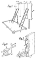
- the present device comprises a series of mounting jumpers 9, such as that shown in FIG. 3.
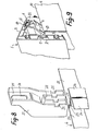
- Each of these jumpers 9 comprises a cage 10 intended to receive the head of a fixing bolt 11, as shown in Figures 9 and 10.
- this cage is open at the end and it has a notch 12 allowing the establishment of such a bolt.
- each of these jumpers has two feet 13 and 14, the ends of which have a dovetail-shaped section so that they can be engaged in the grooves 5 and 6 of the wings 2 and 3 of the frame molding. 1.
- the present device also includes a series of corner junction pieces 8 already mentioned. Viewed in plan from above, each of these parts has the general shape of an L, the two branches 15 of which have ribs 16 on their edges which can be engaged inside the longitudinal grooves 7 at the ends of the moldings d frame to assemble.
- each of these junction pieces 8 is intended to be placed in one of the corners of the frame to be carried out to ensure the end-to-end assembly of the ends of the two corresponding moldings 1, these ends having been previously cut into a miter.
- the ribs 16 having been engaged inside the grooves 7, the attachment of the junction piece 8 on the ends of the moldings is ensured by means of screws 17, as shown in FIG. 6.
- this frame Preferably the components of this frame are assembled flat on the ground, for example on shims, as shown in Figure 1.
- the moldings 1, intended to constitute the different sides of this frame have been cut to the desired length according to the dimensions of the panel 4 to be framed.
- a certain number of mounting jumpers 9 must be put in place on each of these, depending on the number of fasteners provided on the edges of the panel to be framed. The assembly of the moldings can then be carried out very easily by means of the corner joining pieces 8, as shown in FIG. 6.
- the fastening parts provided projecting from the vertical edges of the panel 4 are generally formed by the ends 18 of the horizontal assembly crosspieces 19 existing on the back of this panel to ensure the junction of the various successive sheets 20 constituting it.
- the length of these crosspieces is greater than the width of the panel so that their ends 18 protrude beyond the vertical edges of the latter.
- an oblong slot 18a, elongated in the horizontal direction, which is intended to receive the fixing bolt 11 of a mounting jumper 9, must be provided in each of these ends.
- each of these parts consists of a fixing shoe 21, as illustrated in FIG. 8.
- Each of these shoes has a slot or notch 22 allowing it to be placed astride the edges contiguous 23 of two successive sheets of the panel 4 and this, as shown in FIG. 8. After this installation, such a shoe can be fixed by means of screws passing through the sheets 20 of the panel.
- each of these shoes carries a tab 25, which projects relative to the corresponding horizontal edge of the panel 4, when this shoe is fixed in place.
- jumpers 9 mounted in the vertical sides of the frame are fixed, by assembling them with the projecting ends 18 of the horizontal crosspieces 19 as shown in FIG. 10.
- This fixing is provided in a manner similar to that described above. with regard to the jumpers provided on the horizontal edges.
- Each jumper 9, mounted on a vertical edge of the frame is assembled with the end 18 of a horizontal crosspiece by means of a bolt 11, as shown in FIG. 10.
- the position of the moldings can be adjusted by means of the oblong slots of the various attachment pieces formed by the fixing shoes 21 and the projecting ends 18 of the crosspieces 19.
- each of these jumpers has the advantage of "holding" the corresponding framing molding by the two wings 2 and 3 thereof and not only by one of its wings. The binding thus produced is therefore very robust and prevents risks of deterioration in the event of a depredation test.
- Another advantage of the present device consists in that the fixing of the frame moldings is not ensured by direct bolting on the corresponding attachment parts. Indeed, this fixing is carried out by means of the mounting jumpers 9. This Therefore avoids the risk of breakage of the frame moldings in the event of excessive tightening since the clamping forces are exerted on the mounting jumpers, not directly on the moldings.
- the present framing device is not limited to the embodiment described above.
- the molding elements may very well have a section of shape other than that illustrated in the accompanying drawings. Besides, their front face may possibly not be flat.
- the fixing shoes, shown in FIGS. 8 and 9, can be replaced for any other attachment parts capable of being attached to the horizontal edges of the panel to be framed.
- fasteners specially designed for this purpose can be used instead of using, as fasteners on the vertical edges.
- the fixing of the corner junction pieces 8, on the ends of the moldings to be joined can be ensured by different means, in particular if these moldings do not have longitudinal grooves 7.
- the pieces 8 can be agemcées to catch in the grooves 5 of the moldings to be assembled.
- the present device can be used on various kinds of surfaces to be framed and not only on advertising panels. So it can be used to frame display cases, displays, etc ...
Landscapes
- Physics & Mathematics (AREA)
- General Physics & Mathematics (AREA)
- Engineering & Computer Science (AREA)
- Theoretical Computer Science (AREA)
- Connection Of Plates (AREA)
- Illuminated Signs And Luminous Advertising (AREA)
Applications Claiming Priority (2)
| Application Number | Priority Date | Filing Date | Title |
|---|---|---|---|
| FR8109389 | 1981-05-12 | ||
| FR8109389A FR2506050A1 (fr) | 1981-05-12 | 1981-05-12 | Dispositif pour l'encadrement de panneaux ou de toutes autres surfaces |
Publications (1)
| Publication Number | Publication Date |
|---|---|
| EP0065900A1 true EP0065900A1 (fr) | 1982-12-01 |
Family
ID=9258319
Family Applications (1)
| Application Number | Title | Priority Date | Filing Date |
|---|---|---|---|
| EP82400833A Ceased EP0065900A1 (fr) | 1981-05-12 | 1982-05-06 | Dispositif pour l'encadrement de panneaux ou de toutes autres surfaces |
Country Status (3)
| Country | Link |
|---|---|
| EP (1) | EP0065900A1 (en:Method) |
| ES (1) | ES273598Y (en:Method) |
| FR (1) | FR2506050A1 (en:Method) |
Cited By (1)
| Publication number | Priority date | Publication date | Assignee | Title |
|---|---|---|---|---|
| FR2666164A1 (fr) * | 1990-08-23 | 1992-02-28 | Tri Sarl | Dispositif d'attache de moulures peripheriques de panneaux d'affichage. |
Families Citing this family (3)
| Publication number | Priority date | Publication date | Assignee | Title |
|---|---|---|---|---|
| DE4112551C1 (en) * | 1991-04-17 | 1992-07-16 | Hans Victor 3180 Wolfsburg De Schoenfeld | Frame for poster and notice board surfaces - has top frame parts as flat strips, and convex or concave side top frame parts |
| US11478091B2 (en) * | 2018-02-06 | 2022-10-25 | Mcs Industries, Inc. | Hanging system and bracket thereof |
| USD964844S1 (en) | 2019-01-30 | 2022-09-27 | Mcs Industries, Inc. | Hanging bracket |
Citations (3)
| Publication number | Priority date | Publication date | Assignee | Title |
|---|---|---|---|---|
| US3160973A (en) * | 1961-01-27 | 1964-12-15 | Francis A Ruppelt | Billboard frame |
| FR1435184A (fr) * | 1965-03-05 | 1966-04-15 | Fornells S A Sa | élément d'encadrement décoratif et dispositif de montage et de fixation de celui-ci |
| FR2165027A5 (en:Method) * | 1971-12-15 | 1973-08-03 | Catteau Jean |
-
1981
- 1981-05-12 FR FR8109389A patent/FR2506050A1/fr active Granted
-
1982
- 1982-05-06 EP EP82400833A patent/EP0065900A1/fr not_active Ceased
- 1982-05-11 ES ES1982273598U patent/ES273598Y/es not_active Expired
Patent Citations (3)
| Publication number | Priority date | Publication date | Assignee | Title |
|---|---|---|---|---|
| US3160973A (en) * | 1961-01-27 | 1964-12-15 | Francis A Ruppelt | Billboard frame |
| FR1435184A (fr) * | 1965-03-05 | 1966-04-15 | Fornells S A Sa | élément d'encadrement décoratif et dispositif de montage et de fixation de celui-ci |
| FR2165027A5 (en:Method) * | 1971-12-15 | 1973-08-03 | Catteau Jean |
Cited By (1)
| Publication number | Priority date | Publication date | Assignee | Title |
|---|---|---|---|---|
| FR2666164A1 (fr) * | 1990-08-23 | 1992-02-28 | Tri Sarl | Dispositif d'attache de moulures peripheriques de panneaux d'affichage. |
Also Published As
| Publication number | Publication date |
|---|---|
| ES273598U (es) | 1984-07-16 |
| FR2506050B1 (en:Method) | 1984-05-18 |
| FR2506050A1 (fr) | 1982-11-19 |
| ES273598Y (es) | 1985-02-16 |
Similar Documents
| Publication | Publication Date | Title |
|---|---|---|
| BE1022779A1 (fr) | Systeme d'assemblage de panneaux suivant un diedre pour realiser un meuble et meuble ainsi realise | |
| FR2812680A1 (fr) | Systeme de positionnement et d'assemblage d'une vitre sur un leve-vitre | |
| EP0186217B1 (fr) | Cadre | |
| FR2465044A1 (fr) | Dispositif de fixation de garde-corps et ensemble garde-corps en comportant application | |
| FR2550270A1 (fr) | Dispositif pour le montage et le reglage de l'arbre d'enroulement d'un volet roulant | |
| EP0065900A1 (fr) | Dispositif pour l'encadrement de panneaux ou de toutes autres surfaces | |
| FR2922040A1 (fr) | Dispositif de suspension d'affiche | |
| FR2607847A1 (fr) | Support pour armatures de liaison entre deux elements de construction en beton arme | |
| FR2937901A1 (fr) | Chassis entoile demontable compose de moulures creuses et son dispositif de liaison et d'ecartement des montants droits ou courbes | |
| FR2610861A2 (fr) | Dispositif pour le percage de panneaux de bois en vue de leur assemblage par chevilles | |
| EP3810866B1 (fr) | Procédé et kit de réalisation d'un parement pour une structure | |
| BE1019663A4 (fr) | Ensemble chambranle contre-chambranle. | |
| FR2954391A1 (fr) | Ensemble chambranle contre-chambranle | |
| FR2532038A1 (fr) | Structure elementaire en profiles | |
| FR2575052A1 (fr) | Dispositif destine a equiper un presentoir, ou similaire, pour servir de support a une serie de tiges de suspension d'articles divers, et meubles presentoirs equipes d'un tel dispositif | |
| FR2907484A1 (fr) | Dispositif de blocage en position fermee d'un vantail coulissant dans un dormant | |
| FR2944315A1 (fr) | Systeme de positionnement d'un chassis sur une structure rigide de construction | |
| FR2721343A1 (fr) | Huisserie à profilés ouverts, équipée d'une garniture d'isolation. | |
| FR2541358A1 (fr) | Battant de fenetre ou de porte, en particulier lamelle de porte pliante | |
| FR2688865A1 (fr) | Ensemble pour le support d'au moins un element tel qu'un panneau de signalisation sur au moins un mat. | |
| EP1350964B1 (fr) | Dispositif de maintien et de fixation pour tablette, en particulier en verre, sur un meuble | |
| FR2885442A1 (fr) | Support signaletique | |
| FR2616822A1 (fr) | Dispositif de fixation d'un panneau sur des montants | |
| EP0784304A1 (fr) | Dispositif de porte, notamment pour caisson installé à l'extérieur | |
| FR2772403A1 (fr) | Dispositif pour la fixation d'un poteau a partir d'un support enfonce dans le sol et outil d'enfoncement |
Legal Events
| Date | Code | Title | Description |
|---|---|---|---|
| PUAI | Public reference made under article 153(3) epc to a published international application that has entered the european phase |
Free format text: ORIGINAL CODE: 0009012 |
|
| AK | Designated contracting states |
Designated state(s): BE DE GB IT |
|
| 17P | Request for examination filed |
Effective date: 19830528 |
|
| STAA | Information on the status of an ep patent application or granted ep patent |
Free format text: STATUS: THE APPLICATION HAS BEEN REFUSED |
|
| 18R | Application refused |
Effective date: 19860421 |
|
| RIN1 | Information on inventor provided before grant (corrected) |
Inventor name: FORNELIS, GILBERT |