EP0065873B1 - Construction method - Google Patents
Construction method Download PDFInfo
- Publication number
- EP0065873B1 EP0065873B1 EP82302595A EP82302595A EP0065873B1 EP 0065873 B1 EP0065873 B1 EP 0065873B1 EP 82302595 A EP82302595 A EP 82302595A EP 82302595 A EP82302595 A EP 82302595A EP 0065873 B1 EP0065873 B1 EP 0065873B1
- Authority
- EP
- European Patent Office
- Prior art keywords
- constructional elements
- beams
- base
- constructional
- connectors
- Prior art date
- Legal status (The legal status is an assumption and is not a legal conclusion. Google has not performed a legal analysis and makes no representation as to the accuracy of the status listed.)
- Expired
Links
Images


Classifications
-
- E—FIXED CONSTRUCTIONS
- E04—BUILDING
- E04C—STRUCTURAL ELEMENTS; BUILDING MATERIALS
- E04C3/00—Structural elongated elements designed for load-supporting
- E04C3/38—Arched girders or portal frames
- E04C3/40—Arched girders or portal frames of metal
-
- E—FIXED CONSTRUCTIONS
- E04—BUILDING
- E04B—GENERAL BUILDING CONSTRUCTIONS; WALLS, e.g. PARTITIONS; ROOFS; FLOORS; CEILINGS; INSULATION OR OTHER PROTECTION OF BUILDINGS
- E04B1/00—Constructions in general; Structures which are not restricted either to walls, e.g. partitions, or floors or ceilings or roofs
- E04B1/32—Arched structures; Vaulted structures; Folded structures
- E04B1/3205—Structures with a longitudinal horizontal axis, e.g. cylindrical or prismatic structures
-
- E—FIXED CONSTRUCTIONS
- E04—BUILDING
- E04B—GENERAL BUILDING CONSTRUCTIONS; WALLS, e.g. PARTITIONS; ROOFS; FLOORS; CEILINGS; INSULATION OR OTHER PROTECTION OF BUILDINGS
- E04B1/00—Constructions in general; Structures which are not restricted either to walls, e.g. partitions, or floors or ceilings or roofs
- E04B1/343—Structures characterised by movable, separable, or collapsible parts, e.g. for transport
- E04B1/344—Structures characterised by movable, separable, or collapsible parts, e.g. for transport with hinged parts
- E04B1/3441—Structures characterised by movable, separable, or collapsible parts, e.g. for transport with hinged parts with articulated bar-shaped elements
-
- E—FIXED CONSTRUCTIONS
- E04—BUILDING
- E04B—GENERAL BUILDING CONSTRUCTIONS; WALLS, e.g. PARTITIONS; ROOFS; FLOORS; CEILINGS; INSULATION OR OTHER PROTECTION OF BUILDINGS
- E04B1/00—Constructions in general; Structures which are not restricted either to walls, e.g. partitions, or floors or ceilings or roofs
- E04B1/32—Arched structures; Vaulted structures; Folded structures
- E04B2001/3235—Arched structures; Vaulted structures; Folded structures having a grid frame
- E04B2001/3241—Frame connection details
- E04B2001/3247—Nodes
Definitions
- This invention relates to a method of erecting a structure using constructional elements which are connectable to base plates and joined to each other in an end to end relationship.
- FR-A-2,351,220 described and illustrates a method of erecting a structure comprising the steps of pivotally connecting a constructional element to a first base member, connecting additional constructional elements by hoisting the free end of the connected constructional element to a height sufficient to allow the connection of the additional element to the free end and connecting the free end of the last constructional element to a second base member.
- FR-A-1,315,078 describes and illustrates a method of erecting an arched structure in which a number of prefabricated constructional elements are connected to each other, starting on opposed sides of the arch.
- the method of the present comprises the steps of attaching two or more first base plates to a base for the structure, pivotally connecting two adjacent first constructional elements to their respective first base plates and rigidly connecting the first constructional elements to each other by means of a purlin, fixing connectors to the free ends of the first constructional elements, hoisting the free ends of the first constructional elements and rigidly connecting the connectors to two or more additional constructional elements, rigidly connecting the additional constructional elements to additional purlins and connecting the free ends of the last constructional elements to a pair of second base plates attached to the base.
- the structure is arch-like and the method comprises the preliminary step of cutting the ends of the constructional elements at a predetermined angle, which will depend on the curvature of the arch.
- the method includes the additional step of rigidly securing the structure to the base plates once erected.
- the structure of the invention may be erected, along with a number of similar structures, in the arrangement of a building and, if necessary, the constructional elements may be connected to one another at least in pairs by means of tension members.
- the method therefore includes the additional steps of erecting a plurality of structures in a predetermined arrangement to form a structural whole or building frame and cladding the building frame.
- the optional tension members will be referred to as "cross bracing" or “ties”, for the sake of clarity and to distinguish the same from the purlins.
- the structural elements used as purlins may be the same as the constructional elements, but it will be appreciated that suitable structural elements of a different shape may also be used.
- the structure may be cross braced.
- the constructional element used for carrying out the invention preferably comprises an expanded extruded beam, preferably of metal, which includes a box section on either end of a profiled web, the web being cut, between the profiles at predetermined intervals and expanded.
- each constructional element is optionally provided, along an upper edge thereof, with channels adapted to receive the enlarged edge of a flexible sheet member.
- the connector used for carrying out the invention preferably comprises an extrusion of H-section, the bar of the H being adapted to abut the ends of the constructional elements in use and the legs of the H being adapted to receive the ends of the constructional elements in use.
- the legs of the H and the ends of the constructional elements are preferably formed with holes adapted to receive bolts.
- the bottom connectors may be of H-section, but the remaining connector H-section extrusions may conveniently be provided with at least one bracket on the side of the H, preferably extruded integrally with the H-section.
- the bracket preferably comprises a channel with opposed walls adapted to receive the end of the purlin therebetween.
- the connector may conveniently include a flange on the outside of the H which flange may be provided with means, preferably an aperture formed therein, to receive cross bracing elements.
- a base connector may also be used comprising an extruded box section tube, adapted to fit within the legs of the H of the H-section connectors, which is integral with a wide base.
- the base may be connected to the ground, a foundation or the like.
- the above structure and the method of erecting it is ideally suited for larger industrial or agricultural buildings, or for large temporary structures.
- the constructional elements and connectors can be scaled down for the construction of permanent or temporary domestic buildings.
- the connectors are adapted to allow the hinging of the beams to a position where, in a dismantled form the beams, still connected to one another at their ends, lie adjacent one another.
- the purlins are preferably box- shaped and dimensioned to receive the ends of the beams therein in dismantled form, means being provided to connect an axle to the resultant flat structure to provide a trailable vehicle.
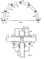
- the structure or arch-like structure 10 shown in Figure 1 is part of the structural whole or frame of a building and comprises a plurality of constructional elements or beams 12 supported on base plates 14.
- the beams 12 are connected to one another by means of connectors 16.
- the arches 10 are erected in pairs, each arch in a pair being connected to the other by means of purlins 18 (shown in cross section in Figure 1) the purlins being the same beams as are used in constructing the arch 10 with the exception that the ends of the purlins are cut at right angles while the ends of the beams 12 are cut at a predetermined angle. This angle will, of course, depend on the curvature of the arch.
- the arch is erected as follows:
- the next pair of connectors 16 is now attached to the free ends of the second connected beams 12b which are then hoisted just high enough for the connection thereto of the next pair of beams 12c.
- the hoisting apparatus being moved from the ends of the first beams 12a to the ends of the second beams 12b.
- a plurality of arches may be erected according to a predetermined plan to provide a building frame comprising pairs of connected arches.
- the resulting pairs of arches may be connected to one another by means of ties or cross bracing extending from flanges 30 which are arranged to project from the connectors 16.
- the connector 16 can be seen in greater detail in the plan view in Figure 2 where the H-section extrusion can be seen to comprise two pairs of legs 24 extending on either side of a cross bar 25.
- the extruded H-section 24 is cut to the desired length which is related to the depth of the beams 12, the ends of which fit between the legs 24 on either side of the cross bar 25.
- bolts and nuts 26 are located in appropriately positioned holes drilled into the box sections of the beams 12 and the legs 24 of the H.
- the H-section is extruded integrally with two channel formations 27, one on either side of the H.
- the channel formations 27 comprise two walls 28 adapted to receive the purlins 18, which are the same or similar to as the arch beams 12.
- the walls 28, in fact, provide the brackets to support the purlin beams 18 and are provided with appropriately positioned holes for bolts and nuts 29 which, once again, pass through the box sections of the beams 18.
- flanges 30 are provided on either side of the connectors 16 and formed with the holes 32 for the cross bracing or tie rods which, in the completed building frame, will extend between the pair of arches and, if necessary, between the arches in a pair. It will be appreciated that, in situations where the arches in a pair are connected to one another by means of purlins extending between the two and without cross bracing, and where the cross bracing extends between adjacent pairs of arches, the brackets 28 need be provided only on one side of the H while the flange 30 need be provided only on the other side of the H.
- the beams 12 are produced from an aluminium extrusion which is shown in Figure 3 to comprise a profiled web 34 with a box section 36, 38 on either side thereof.
- the upper box section 38 is optionally provided with a double sided channel section, the purpose of which will be described below.
- the profiled web 34 is cut between the profiles at predetermined intervals which will depend on the desired final shape of the beam.
- the cuts between adjacent profiles are staggered and the extrusion is then gripped by mechanical means at the box sections which are then pulled apart to expand the web into the diamond pattern shown in Figure 5. This process is well known and described in several South African patents to Jury and Spiers (Pty) Limited.
- the beams 12 of the arches and the beams 18 of the purlins are both the same or similar as has been mentioned above.
- the ends of the beams 12 are cut at an angle which will, of course depend on the desired curvature of the arch, while the ends of the purlin beams 18 are cut at right angles to the longitudinal axes thereof.
- Figure 5 also shows the connector 16 in side elevation in position on a purlin 18 where it can be seen how the flange 30 on one side of the connector 16 fits between the ties 34a formed by the expanded web of the beam.
- the base connector 114 shown in Figure 6. This connector has dimensions similar to the end of the beam 12 so that it fits within the legs H connector 16.
- the base connector 114 includes a wide base 114a with the tubular box section projection 114b which fits within the legs of the H as has been mentioned above.
- the projection 114b is jig drilled as are the other components of the system, for the location of bolts.
- the base may be provided with ground spikes (not shown) which may be cemented to the concrete base 100 of the building.
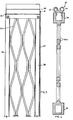
- Figure 7 shows a light weight structure 200 embodying the principles of the invention.
- the structure comprises beams 202, connectors 204 and purlins 206.
- a fabric cover 208 is provided and poles 210 spread the fabric on either side of the structure.
- Pegs or spikes 212 are provided to hold lines 214 which secure the poles and similar pegs hold the base plates 214 and the beams 202 in position.
- the structure 200 can be dismantled and converted into a trailer by removing only some of the bolts in the connectors and folding or hinging the still connected beams with their free ends towards one another in zig zag fashion.
- the hinged beams are laid flat and the channel shaped purlins 206 are slid over the ends of the beams and the connectors and bolted into position forming a flat structure.
- An axle assembly (not shown) and a towbar assembly (not shown) are provided and once these are bolted in position the structure is converted to a trailable vehicle on which the fabric cover and other goods can be loaded.
- This structure 200 is useful as temporary garage, tent or the like.
- the frame may be clad with conventional sheet material cladding such as roofing sheets.
- sheet material cladding such as roofing sheets.
- sheets of flexible material or tarpaulins of canvas, plastics impregnated canvas or a synthetic textile may be used.
- the sheets Prior to their location on the structure, the sheets will be provided with rope reinforced edges or similarly enlarged edges along two sides thereof which are then drawn into the channels 42 and 44 provided along the upper box sections 38 of the beams 12 of two adjacent arches 10. The sheets will, of course, be drawn into the facing channels of two adjacent arches to span the space between the adjacent arches 10.
- the sheets may be pulled, by means of ropes located in the channels 42 and 44, from one side of the frame completely over frame to the other side. If an appropriately sized rope reinforcing edge is used, the joints between the beams 12 and the sheet material should be water proof.
- constructional elements and connectors can be mass produced and bolted together without scaffolding or the like.
- the structures can be erected largely with unskilled labour.
- the structural method and means provided is particularly suitable for temporary buildings as the building and building frames can be dismantled and re-erected rapidly some other place.
Description
- This invention relates to a method of erecting a structure using constructional elements which are connectable to base plates and joined to each other in an end to end relationship.
- FR-A-2,351,220 described and illustrates a method of erecting a structure comprising the steps of pivotally connecting a constructional element to a first base member, connecting additional constructional elements by hoisting the free end of the connected constructional element to a height sufficient to allow the connection of the additional element to the free end and connecting the free end of the last constructional element to a second base member.
- FR-A-1,315,078 describes and illustrates a method of erecting an arched structure in which a number of prefabricated constructional elements are connected to each other, starting on opposed sides of the arch.
- The method of the present comprises the steps of attaching two or more first base plates to a base for the structure, pivotally connecting two adjacent first constructional elements to their respective first base plates and rigidly connecting the first constructional elements to each other by means of a purlin, fixing connectors to the free ends of the first constructional elements, hoisting the free ends of the first constructional elements and rigidly connecting the connectors to two or more additional constructional elements, rigidly connecting the additional constructional elements to additional purlins and connecting the free ends of the last constructional elements to a pair of second base plates attached to the base.
- In a preferred form of the invention, the structure is arch-like and the method comprises the preliminary step of cutting the ends of the constructional elements at a predetermined angle, which will depend on the curvature of the arch.
- The method includes the additional step of rigidly securing the structure to the base plates once erected.
- The structure of the invention may be erected, along with a number of similar structures, in the arrangement of a building and, if necessary, the constructional elements may be connected to one another at least in pairs by means of tension members. The method therefore includes the additional steps of erecting a plurality of structures in a predetermined arrangement to form a structural whole or building frame and cladding the building frame.
- The optional tension members will be referred to as "cross bracing" or "ties", for the sake of clarity and to distinguish the same from the purlins. The structural elements used as purlins may be the same as the constructional elements, but it will be appreciated that suitable structural elements of a different shape may also be used.
- In addition to the purlins connecting adjacent constructional elements, the structure may be cross braced.
- The constructional element used for carrying out the invention preferably comprises an expanded extruded beam, preferably of metal, which includes a box section on either end of a profiled web, the web being cut, between the profiles at predetermined intervals and expanded.
- In a preferred form of the invention each constructional element is optionally provided, along an upper edge thereof, with channels adapted to receive the enlarged edge of a flexible sheet member.
- The connector used for carrying out the invention preferably comprises an extrusion of H-section, the bar of the H being adapted to abut the ends of the constructional elements in use and the legs of the H being adapted to receive the ends of the constructional elements in use.
- The legs of the H and the ends of the constructional elements are preferably formed with holes adapted to receive bolts.
- The bottom connectors may be of H-section, but the remaining connector H-section extrusions may conveniently be provided with at least one bracket on the side of the H, preferably extruded integrally with the H-section. The bracket preferably comprises a channel with opposed walls adapted to receive the end of the purlin therebetween.
- The connector may conveniently include a flange on the outside of the H which flange may be provided with means, preferably an aperture formed therein, to receive cross bracing elements.
- A base connector may also be used comprising an extruded box section tube, adapted to fit within the legs of the H of the H-section connectors, which is integral with a wide base.
- The base may be connected to the ground, a foundation or the like.
- The above structure and the method of erecting it is ideally suited for larger industrial or agricultural buildings, or for large temporary structures. However the constructional elements and connectors can be scaled down for the construction of permanent or temporary domestic buildings.
- In one such form the connectors are adapted to allow the hinging of the beams to a position where, in a dismantled form the beams, still connected to one another at their ends, lie adjacent one another. The purlins are preferably box- shaped and dimensioned to receive the ends of the beams therein in dismantled form, means being provided to connect an axle to the resultant flat structure to provide a trailable vehicle.
- The invention is further described with reference to the accompanying drawings in which:-
- Figure 1 is a diagrammatic sectional side elevation of an arch-like structure according to the invention;
- Figure 2 is a plan view of a part of the structure showing the connector;
- Figure 3 is a cross section through an unexpanded extruded beam;
- Figure 4 is a cross section through an expanded beam;
- Figure 5 is a side elevation of a part of an expanded beam;
- Figure 6 is an end elevation of a base connection; and
- Figure 7 is an end elevation of a light-weight temporary structure.
- The structure or arch-like structure 10 shown in Figure 1 is part of the structural whole or frame of a building and comprises a plurality of constructional elements or
beams 12 supported onbase plates 14. Thebeams 12 are connected to one another by means ofconnectors 16. The arches 10 are erected in pairs, each arch in a pair being connected to the other by means of purlins 18 (shown in cross section in Figure 1) the purlins being the same beams as are used in constructing the arch 10 with the exception that the ends of the purlins are cut at right angles while the ends of thebeams 12 are cut at a predetermined angle. This angle will, of course, depend on the curvature of the arch. - The arch is erected as follows:
- The base 11 is prepared. This is normally a level site which is provided with a concrete screed and the
base plates 14 are placed in position. A pair of first beams 12a are pivotally connected to theirrespect base plates 14 by means of bolts andnuts 20. The beams 12a are allowed to lie virtually flat on the ground. Theconnectors 16 are now attached to the ends of the beams 12a in a manner to be described below and thepurlin 18 between the two beams 12a is connected to theconnector 16. The next pair of beams 12b is now attached, each beam 12b in the pair being connected to its respective connector. To do this the free ends of the connected beams 12a are lifted clear of the ground to allow the rigid connection thereto of the next or additional beams 12b. It will be appreciated that the beams 12a need not be hoisted to their final position, it is sufficient merely to hoist them high enough for the free ends of the beams 12b to rest on the ground. - The next pair of
connectors 16 is now attached to the free ends of the second connected beams 12b which are then hoisted just high enough for the connection thereto of the next pair of beams 12c. The hoisting apparatus being moved from the ends of the first beams 12a to the ends of the second beams 12b. - In this manner the whole arch 10 is erected by merely lifting the free ends of each connected beam pair to allow the attachment thereto of the next beam until the last pair of
beams 12d are fixed in place which beams are then connected to the second base plates on the other side of the structure by means of bolts andnuts 22. The arch 10 may now be rigidly connected to the first base plate by means ofbolts 23. - In this manner a plurality of arches may be erected according to a predetermined plan to provide a building frame comprising pairs of connected arches. The resulting pairs of arches may be connected to one another by means of ties or cross bracing extending from
flanges 30 which are arranged to project from theconnectors 16. - The side elevation of Figure 1, being diagrammatic, does not show the diamond pattern of the webs which will be described below.
- The
connector 16 can be seen in greater detail in the plan view in Figure 2 where the H-section extrusion can be seen to comprise two pairs oflegs 24 extending on either side of a cross bar 25. The extruded H-section 24 is cut to the desired length which is related to the depth of thebeams 12, the ends of which fit between thelegs 24 on either side of the cross bar 25. To secure theconnector 16 to thebeams 12, bolts andnuts 26 are located in appropriately positioned holes drilled into the box sections of thebeams 12 and thelegs 24 of the H. The H-section is extruded integrally with twochannel formations 27, one on either side of the H. Thechannel formations 27 comprise twowalls 28 adapted to receive thepurlins 18, which are the same or similar to as thearch beams 12. Thewalls 28, in fact, provide the brackets to support thepurlin beams 18 and are provided with appropriately positioned holes for bolts and nuts 29 which, once again, pass through the box sections of thebeams 18. - In addition to the
extruded legs 24 andbrackets 28,flanges 30 are provided on either side of theconnectors 16 and formed with theholes 32 for the cross bracing or tie rods which, in the completed building frame, will extend between the pair of arches and, if necessary, between the arches in a pair. It will be appreciated that, in situations where the arches in a pair are connected to one another by means of purlins extending between the two and without cross bracing, and where the cross bracing extends between adjacent pairs of arches, thebrackets 28 need be provided only on one side of the H while theflange 30 need be provided only on the other side of the H. - The
beams 12 are produced from an aluminium extrusion which is shown in Figure 3 to comprise a profiledweb 34 with abox section upper box section 38 is optionally provided with a double sided channel section, the purpose of which will be described below. - To arrive at the shape shown in Figures 4 and 5, the profiled
web 34 is cut between the profiles at predetermined intervals which will depend on the desired final shape of the beam. The cuts between adjacent profiles are staggered and the extrusion is then gripped by mechanical means at the box sections which are then pulled apart to expand the web into the diamond pattern shown in Figure 5. This process is well known and described in several South African patents to Jury and Spiers (Pty) Limited. - The
beams 12 of the arches and thebeams 18 of the purlins are both the same or similar as has been mentioned above. The ends of thebeams 12 are cut at an angle which will, of course depend on the desired curvature of the arch, while the ends of thepurlin beams 18 are cut at right angles to the longitudinal axes thereof. - Figure 5 also shows the
connector 16 in side elevation in position on apurlin 18 where it can be seen how theflange 30 on one side of theconnector 16 fits between theties 34a formed by the expanded web of the beam. - An alternative to the
base 14 is the use of thebase connector 114 shown in Figure 6. This connector has dimensions similar to the end of thebeam 12 so that it fits within thelegs H connector 16. Thebase connector 114 includes a wide base 114a with the tubular box section projection 114b which fits within the legs of the H as has been mentioned above. The projection 114b is jig drilled as are the other components of the system, for the location of bolts. The base may be provided with ground spikes (not shown) which may be cemented to theconcrete base 100 of the building. - Figure 7 shows a
light weight structure 200 embodying the principles of the invention. The structure comprisesbeams 202,connectors 204 andpurlins 206. - A
fabric cover 208 is provided and poles 210 spread the fabric on either side of the structure. Pegs or spikes 212 are provided to holdlines 214 which secure the poles and similar pegs hold thebase plates 214 and thebeams 202 in position. - The
structure 200 can be dismantled and converted into a trailer by removing only some of the bolts in the connectors and folding or hinging the still connected beams with their free ends towards one another in zig zag fashion. The hinged beams are laid flat and the channel shapedpurlins 206 are slid over the ends of the beams and the connectors and bolted into position forming a flat structure. An axle assembly (not shown) and a towbar assembly (not shown) are provided and once these are bolted in position the structure is converted to a trailable vehicle on which the fabric cover and other goods can be loaded. Thisstructure 200 is useful as temporary garage, tent or the like. - Once the structure is erected and all the arches in the building frame are rigidly connected, the frame may be clad with conventional sheet material cladding such as roofing sheets. Alternatively sheets of flexible material or tarpaulins of canvas, plastics impregnated canvas or a synthetic textile may be used. Prior to their location on the structure, the sheets will be provided with rope reinforced edges or similarly enlarged edges along two sides thereof which are then drawn into the
channels upper box sections 38 of thebeams 12 of two adjacent arches 10. The sheets will, of course, be drawn into the facing channels of two adjacent arches to span the space between the adjacent arches 10. With properly designed leaders, the sheets may be pulled, by means of ropes located in thechannels beams 12 and the sheet material should be water proof. - It will be appreciated that the constructional elements and connectors can be mass produced and bolted together without scaffolding or the like. In addition, due to the simplicity of the elements involved, the structures can be erected largely with unskilled labour. The structural method and means provided is particularly suitable for temporary buildings as the building and building frames can be dismantled and re-erected rapidly some other place.
Claims (2)
Applications Claiming Priority (2)
| Application Number | Priority Date | Filing Date | Title |
|---|---|---|---|
| ZA813421 | 1981-05-21 | ||
| ZA813421 | 1981-05-21 |
Publications (3)
| Publication Number | Publication Date |
|---|---|
| EP0065873A2 EP0065873A2 (en) | 1982-12-01 |
| EP0065873A3 EP0065873A3 (en) | 1983-02-09 |
| EP0065873B1 true EP0065873B1 (en) | 1986-10-01 |
Family
ID=25575422
Family Applications (1)
| Application Number | Title | Priority Date | Filing Date |
|---|---|---|---|
| EP82302595A Expired EP0065873B1 (en) | 1981-05-21 | 1982-05-20 | Construction method |
Country Status (10)
| Country | Link |
|---|---|
| EP (1) | EP0065873B1 (en) |
| JP (1) | JPS5817945A (en) |
| AR (1) | AR230304A1 (en) |
| AU (1) | AU552013B2 (en) |
| BR (1) | BR8202932A (en) |
| CA (1) | CA1200962A (en) |
| DE (1) | DE3273524D1 (en) |
| DK (1) | DK152716C (en) |
| FI (1) | FI81162C (en) |
| NZ (1) | NZ200704A (en) |
Families Citing this family (7)
| Publication number | Priority date | Publication date | Assignee | Title |
|---|---|---|---|---|
| DE3822446A1 (en) * | 1988-02-25 | 1989-09-07 | Dieter Knauer | Load-bearing element |
| ZA902575B (en) * | 1989-04-07 | 1991-01-30 | Ronald Harding Lewis | Frame structure |
| US5159790A (en) * | 1989-04-07 | 1992-11-03 | Harding Lewis R | Frame structure |
| CN1109789C (en) * | 1992-03-02 | 2003-05-28 | 谢锡范 | Corrugated thin-cased arch |
| ES2298032B1 (en) * | 2006-05-11 | 2009-08-03 | Cualimetal, S.A. | METALLIC STRUCTURE FOR INDUSTRIAL AND SIMILAR VESSELS. |
| CN106978883A (en) * | 2017-03-31 | 2017-07-25 | 天津城建大学 | A kind of folding beam string |
| CN114016607B (en) * | 2021-11-05 | 2022-11-25 | 赣州博泰钢结构工程有限公司 | Steel structure with high stability and use method thereof |
Family Cites Families (15)
| Publication number | Priority date | Publication date | Assignee | Title |
|---|---|---|---|---|
| GB117994A (en) * | 1917-09-14 | 1918-08-15 | Bertram Lawrance Hurst | Improvements in or relating to Huts, Sheds, Warehouses and other Buildings. |
| US2797696A (en) * | 1952-06-16 | 1957-07-02 | Carl B Fritsche | Collapsible shelters and tents |
| US3080875A (en) * | 1958-04-11 | 1963-03-12 | John P Bartlett | Frame support structures |
| US3283464A (en) * | 1960-05-10 | 1966-11-08 | Litzka Franz | Honeycomb girders and method for making same |
| FR1315078A (en) * | 1960-11-21 | 1963-01-18 | Improvements to structures, especially roofs | |
| AU5978065A (en) * | 1966-06-02 | 1967-12-14 | Ernst Baumwald | Building construction from standard members |
| ES153976Y (en) * | 1969-12-04 | 1971-08-01 | Garcia Martinez | STRUCTURE FOR THE ASSEMBLY OF PREFABRICATED CONSTRUCTIONS. |
| FR2137123A1 (en) * | 1971-05-07 | 1972-12-29 | Schmitt Jose | |
| AU425337B2 (en) * | 1971-07-22 | 1972-06-15 | Jury + Spiers Proprietary Ltd. | Improvements in expanded structural members |
| JPS5325119B2 (en) * | 1973-03-09 | 1978-07-25 | ||
| FI52378C (en) * | 1975-10-10 | 1977-08-10 | Pentti Sohlberg | Canopy frame. |
| SE409738B (en) * | 1976-05-14 | 1979-09-03 | Lindblad Leif Ab | EASY ASSEMBLY AND DISASSEMBLY BUILDING AND KIT FOR ASSEMBLY THEREOF |
| DE2646050A1 (en) * | 1976-10-13 | 1978-04-20 | Berke Friedrich Ohg | Welt for tent canvas - is inserted into metal profiled sections, loops round rope and is positioned by plastic spacer pieces |
| GB1590416A (en) * | 1977-04-12 | 1981-06-03 | Shelter Span Building Syst | Building structures incorporating tensioned covering |
| JPS5539513A (en) * | 1978-09-10 | 1980-03-19 | Yoshihiro Yonahara | Simply assembled structure |
-
1982
- 1982-04-20 FI FI821797A patent/FI81162C/en not_active IP Right Cessation
- 1982-05-20 EP EP82302595A patent/EP0065873B1/en not_active Expired
- 1982-05-20 DE DE8282302595T patent/DE3273524D1/en not_active Expired
- 1982-05-20 BR BR8202932A patent/BR8202932A/en not_active IP Right Cessation
- 1982-05-21 CA CA000403590A patent/CA1200962A/en not_active Expired
- 1982-05-21 AR AR289481A patent/AR230304A1/en active
- 1982-05-21 JP JP57086362A patent/JPS5817945A/en active Pending
- 1982-05-21 DK DK230882A patent/DK152716C/en not_active IP Right Cessation
- 1982-05-21 AU AU84036/82A patent/AU552013B2/en not_active Ceased
- 1982-05-21 NZ NZ200704A patent/NZ200704A/en unknown
Also Published As
| Publication number | Publication date |
|---|---|
| DK152716C (en) | 1988-09-19 |
| CA1200962A (en) | 1986-02-25 |
| EP0065873A3 (en) | 1983-02-09 |
| BR8202932A (en) | 1983-05-03 |
| EP0065873A2 (en) | 1982-12-01 |
| AU552013B2 (en) | 1986-05-22 |
| AU8403682A (en) | 1982-11-25 |
| DE3273524D1 (en) | 1986-11-06 |
| FI821797A0 (en) | 1982-04-20 |
| NZ200704A (en) | 1985-02-28 |
| FI81162B (en) | 1990-05-31 |
| DK230882A (en) | 1982-11-22 |
| FI81162C (en) | 1990-09-10 |
| AR230304A1 (en) | 1984-03-01 |
| JPS5817945A (en) | 1983-02-02 |
| DK152716B (en) | 1988-04-25 |
Similar Documents
| Publication | Publication Date | Title |
|---|---|---|
| US4961297A (en) | Transportable weather resistant building enclosure | |
| HU221798B1 (en) | Prefabricated building systems | |
| US7325362B1 (en) | Steel roof truss system | |
| EP0065873B1 (en) | Construction method | |
| US3676964A (en) | Frame and building structure and method of constructing same | |
| US4294052A (en) | Prefabricated load bearing structure | |
| GB2037838A (en) | A Foldable Prefabricated Building Structure | |
| EP0090473A1 (en) | Building, wall sections and profiles for the same | |
| US3410041A (en) | Building structures with an intermediate floor and socket-connected uprights | |
| JP2573545B2 (en) | Construction method of temporary tent for construction | |
| JP2585174B2 (en) | How to fix scaffolding for temporary tents | |
| EP0086201B1 (en) | Portal frame | |
| US4137684A (en) | Building panel | |
| JP2001081865A (en) | Roof structure and construction method therefor | |
| JP6894422B2 (en) | Unit house structure | |
| JP2601107B2 (en) | All-weather temporary roof and its use | |
| AU8150487A (en) | Modular building | |
| SU857378A1 (en) | Building large-block foldable section | |
| SU894149A1 (en) | Collapsible scaffolding | |
| RU33590U1 (en) | Building panel and prefabricated panel building | |
| SU649802A1 (en) | Curvilinear roof of buildings and structures | |
| SU702134A1 (en) | Collapsible section of a building | |
| RU2385995C1 (en) | Reinforced metal block | |
| SU1013608A1 (en) | Form for erecting cast-in-place reinforced concrete structures | |
| EP0500322B1 (en) | Portable building modules |
Legal Events
| Date | Code | Title | Description |
|---|---|---|---|
| PUAI | Public reference made under article 153(3) epc to a published international application that has entered the european phase |
Free format text: ORIGINAL CODE: 0009012 |
|
| AK | Designated contracting states |
Designated state(s): BE CH DE FR GB IT LI LU NL SE |
|
| PUAL | Search report despatched |
Free format text: ORIGINAL CODE: 0009013 |
|
| AK | Designated contracting states |
Designated state(s): BE CH DE FR GB IT LI LU NL SE |
|
| 17P | Request for examination filed |
Effective date: 19830809 |
|
| GRAA | (expected) grant |
Free format text: ORIGINAL CODE: 0009210 |
|
| AK | Designated contracting states |
Kind code of ref document: B1 Designated state(s): BE CH DE FR GB IT LI LU NL SE |
|
| PG25 | Lapsed in a contracting state [announced via postgrant information from national office to epo] |
Ref country code: IT Free format text: LAPSE BECAUSE OF FAILURE TO SUBMIT A TRANSLATION OF THE DESCRIPTION OR TO PAY THE FEE WITHIN THE PRESCRIBED TIME-LIMIT;WARNING: LAPSES OF ITALIAN PATENTS WITH EFFECTIVE DATE BEFORE 2007 MAY HAVE OCCURRED AT ANY TIME BEFORE 2007. THE CORRECT EFFECTIVE DATE MAY BE DIFFERENT FROM THE ONE RECORDED. Effective date: 19861001 Ref country code: FR Free format text: THE PATENT HAS BEEN ANNULLED BY A DECISION OF A NATIONAL AUTHORITY Effective date: 19861001 Ref country code: BE Effective date: 19861001 |
|
| PG25 | Lapsed in a contracting state [announced via postgrant information from national office to epo] |
Ref country code: SE Effective date: 19861031 |
|
| REF | Corresponds to: |
Ref document number: 3273524 Country of ref document: DE Date of ref document: 19861106 |
|
| EN | Fr: translation not filed | ||
| PG25 | Lapsed in a contracting state [announced via postgrant information from national office to epo] |
Ref country code: LU Free format text: LAPSE BECAUSE OF NON-PAYMENT OF DUE FEES Effective date: 19870531 |
|
| PLBE | No opposition filed within time limit |
Free format text: ORIGINAL CODE: 0009261 |
|
| STAA | Information on the status of an ep patent application or granted ep patent |
Free format text: STATUS: NO OPPOSITION FILED WITHIN TIME LIMIT |
|
| 26N | No opposition filed | ||
| PGFP | Annual fee paid to national office [announced via postgrant information from national office to epo] |
Ref country code: NL Payment date: 19910531 Year of fee payment: 10 |
|
| PGFP | Annual fee paid to national office [announced via postgrant information from national office to epo] |
Ref country code: CH Payment date: 19910826 Year of fee payment: 10 |
|
| PGFP | Annual fee paid to national office [announced via postgrant information from national office to epo] |
Ref country code: GB Payment date: 19920519 Year of fee payment: 11 |
|
| PGFP | Annual fee paid to national office [announced via postgrant information from national office to epo] |
Ref country code: DE Payment date: 19920527 Year of fee payment: 11 |
|
| PG25 | Lapsed in a contracting state [announced via postgrant information from national office to epo] |
Ref country code: LI Effective date: 19920531 Ref country code: CH Effective date: 19920531 |
|
| PG25 | Lapsed in a contracting state [announced via postgrant information from national office to epo] |
Ref country code: NL Effective date: 19921201 |
|
| NLV4 | Nl: lapsed or anulled due to non-payment of the annual fee | ||
| REG | Reference to a national code |
Ref country code: CH Ref legal event code: PL |
|
| PG25 | Lapsed in a contracting state [announced via postgrant information from national office to epo] |
Ref country code: GB Effective date: 19930520 |
|
| GBPC | Gb: european patent ceased through non-payment of renewal fee |
Effective date: 19930520 |
|
| PG25 | Lapsed in a contracting state [announced via postgrant information from national office to epo] |
Ref country code: DE Effective date: 19940201 |