EP0086201B1 - Portal frame - Google Patents
Portal frame Download PDFInfo
- Publication number
- EP0086201B1 EP0086201B1 EP19820902361 EP82902361A EP0086201B1 EP 0086201 B1 EP0086201 B1 EP 0086201B1 EP 19820902361 EP19820902361 EP 19820902361 EP 82902361 A EP82902361 A EP 82902361A EP 0086201 B1 EP0086201 B1 EP 0086201B1
- Authority
- EP
- European Patent Office
- Prior art keywords
- roof
- members
- pair
- sections
- plate
- Prior art date
- Legal status (The legal status is an assumption and is not a legal conclusion. Google has not performed a legal analysis and makes no representation as to the accuracy of the status listed.)
- Expired
Links
Images


Classifications
-
- E—FIXED CONSTRUCTIONS
- E04—BUILDING
- E04B—GENERAL BUILDING CONSTRUCTIONS; WALLS, e.g. PARTITIONS; ROOFS; FLOORS; CEILINGS; INSULATION OR OTHER PROTECTION OF BUILDINGS
- E04B1/00—Constructions in general; Structures which are not restricted either to walls, e.g. partitions, or floors or ceilings or roofs
- E04B1/343—Structures characterised by movable, separable, or collapsible parts, e.g. for transport
- E04B1/344—Structures characterised by movable, separable, or collapsible parts, e.g. for transport with hinged parts
- E04B1/3441—Structures characterised by movable, separable, or collapsible parts, e.g. for transport with hinged parts with articulated bar-shaped elements
Definitions
- the invention relates to a portal frame for a building of the kind commonly referred to as a prefabricated building or buildings including such frames.
- a portal frame for a building of the kind commonly referred to as a prefabricated building or buildings including such frames The erection on site of known prefabricated buildings requires the attendance of workmen with special skills and experience, thereby increasing the building cost. Where such workmen are not available, prefabricated buildings may not be constructed within required safety standards.
- United States Patent No. 2642825 describes a lattice truss which can be made up of two mirror sections which are individually foldable for transportation.
- French Patent No. 2367155 also describes a lattice truss which can be erected from a folded condition.
- United States Patent No. 3846953 describes a method of erecting a roof where two members are hinged together. One is lifted to a desired angle allowing the other to pivot vertically downwardly. From this position it can be pulled into the required angular relationship with respect to the first member.
- a portal frame comprising a pair of roof members and a pair of support members, the roof members being interconnected by a plate, which allows pivoting of the roof members with respect to one another, and each roof member being connected to a respective support member by a further plate, the further plate being fixed to one of the pair of roof and support members and pivotally connected to the other whereby the frame can be transported in a folded condition, wherein the roof members lie between the support members in a generally parallel configuration, and whereby the frame can be erected by unfolding it such that the roof members are generally level with one another, lifting the roof members so that they are pivoted into a required angular relationship, fixing the roof members together by further fixing to the plate to maintain the angular relation, lifting the roof members a further amount so that the support members pivot into a required angular relation relative to the respective roof member and. fixing each support member to its respective roof member by fixing its respective further plate to the other of the pair of roof and support members.
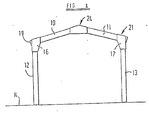
- Figure 1 shows an erected building of the ridge roof variety and comprises at least two roof sections 10 and 11 and at least two side wall sections 12 and 13.
- the building is shown standing on a concrete base 14.
- the number of sections in the roof depends on the length of the building and the number in the side walls is equal to the number in the roof.
- FIG. 4 shows an elevation of the roof section 10.
- Each roof section is formed of two corrugated panels 25 fitted on a framework of elongate members.
- the corrugations are perpendicular to a ridge 24 formed by the sections.
- Channel section members 26a and 26b are fitted about respective corrugations at the side margins of each panel.
- Members 26a are riveted back-to-back in the assembled section.
- Cross beams 27a and 27b secured to members 26a and 26b at opposite ends thereof strengthen the section.
- Connecting elements shown in Figures 2 and 3 are used for connecting respective sections.
- Figure 2 shows an apex plate 15 used for connecting roof sections 10 and 11 together at respective margins of these sections which are required to be adjacent to the apex of the building.
- Figure 3 shows an eaves plate 16 for connecting roof section 10 with wall section 12 at respective margins of these sections which are required to be adjacent to the eaves.
- An identical eaves plate 17 is used for connecting roof section 11 with wall section 13.
- the connecting elements 15,16,17 are suitably formed of steel.
- apex plates 15 are rigidly connected to the roof section 11 adjacent to that cross beam 27a which is required to be adjacent to the apex of the building in such a manner that the plates project beyond the adjacent margin of the roof panel.
- Two of the apex plates are disposed at respective further margins of the section 10 so that the margin which is required to lie adjacent to the apex extends between the plates.
- the third apex plate 15 is engaged between the pair of channel section members 26a to project from the apex margin of the section.
- the surfaces of the apex plates are in face-to-face contact with surfaces of the members 26 and are substantially perpendicular to the ridge formed by the roof sections in the erected building.
- Three eaves plates 16 are rigidly connected in a similar way to the roof section 10 adjacent to the margin 19 of that section which is required to lie adjacent to the eaves of the building.
- Three eaves plates 17 are secured in a similar manner to the roof section 11 to project from the roof section in the manner shown in the drawings.
- the apex plates 15 project from the section 11 generally in a direction beyond the end of that section; whereas the eaves plates 16 and 17 project from the sections 10 and 11 in a direction which is a downward direction in the completed building and is thus transverse to the lengths of the roof sections.
- each apex plate 15 Prior to erection each apex plate 15 is connected by several bolts to the roof section 11; whereas a single bolt 25 may connect the apex plate to the section 10.
- the assembled roof sections 10 and 11 are then raised from their horizontal attitudes by means of lifting apparatus.
- the sections are suspended from the lifting apparatus at points on the apex plates which are adjacent to the members 26b.
- the sections 10 and 11 undergo relative pivoting until they are mutually inclined at the required angle.
- the connection between the apex plates and the section 10 is then changed so that further relative pivoting is restrained.
- Additional bolts are used to secure the apex plates to the section 10. Since, at this stage of assembly, the roof sections are still near to the ground, the bolts can be inserted by workman standing on the ground. Workmen standing on the ground can also apply caps to the ridge defined by the sections 10 and 11 to close any gap between them.
- roof sections and wall sections are then raised by the lifting apparatus until the wall sections are substantially vertical. Further bolts are then used to fix the eaves plates 16 rigidly to the wall sections 12 and 13. The wall sections are then fixed rigidly to the concrete base 14.
- ends can be fitted to the building.
- One or both ends may comprise a door or shutter (not shown).
- the procedure of erecting the building can be reversed to disassemble the building for transport to a different site.
- each unit comprising a pair of roof sections 10, 11, apex plates 15, a pair of wall sections 12, 13 and eaves plates 17 are made up, preferably at the site where the panels are produced.
- the eaves plates are rigidly connected with the roof sections but are each connected by means of a respective single bolt with a corresponding wall section so that the wall sections can pivot relative to the eaves plates.
- Each of the apex plates is connected to each roof section by a respective single bolt so that both roof sections can pivot relative to the apex plate.
- the sections rest one on the other with the roof sections lying between the wall sections so that the unit has a compact configuration with substantially parallel upper and lower surfaces.
- These units can be stacked one on the other for transport to a site where the building is to be erected.
- Each unit is unloaded from the transport vehicle and placed on the ground with one wall section lowermost and the other wall section uppermost.
- the uppermost wall section and the immediately adjacent roof section are then pivoted together relative to the other roof section until both wall sections rest on the ground.
- the eaves plates of the unit are then raised until the required angular relation is established between the roof sections and the apex plates.
- the roof sections are then made rigid with the apex plates by use of additional fasteners. Subsequently, the roof sections are raised further and the procedure hereinbefore described is followed to complete erection of the unit and a number of additional units are erected, according to the required length of the building.
- one or more tie bars may be connected to each roof section at a position between the eaves and the apex of the roof to stiffen the structure.
- elongate members 26a and'26b Whilst we prefer to secure the elongate members 26a and'26b to panels 25 to form sections, prior to erection of the elongate members on the building site, it is within the scope of the invention to pivotally connect a pair of elongate members 26b by means of an apex plate 15, to raise the apex plate and then secure the pair of elongate members against relative pivoting, pivotally connect further elongate members one with each of the members 26b and further raise the apex plate until the further elongate members are vertical, thereby forming a portal frame, erecting a further portal frame in a similar manner and then mounting panels on the portal frames to span the gap between them.
Description
- The invention relates to a portal frame for a building of the kind commonly referred to as a prefabricated building or buildings including such frames. The erection on site of known prefabricated buildings requires the attendance of workmen with special skills and experience, thereby increasing the building cost. Where such workmen are not available, prefabricated buildings may not be constructed within required safety standards.
- United States Patent No. 2642825 describes a lattice truss which can be made up of two mirror sections which are individually foldable for transportation. French Patent No. 2367155 also describes a lattice truss which can be erected from a folded condition. United States Patent No. 3846953 describes a method of erecting a roof where two members are hinged together. One is lifted to a desired angle allowing the other to pivot vertically downwardly. From this position it can be pulled into the required angular relationship with respect to the first member.
- From one aspect of the invention, there is provided a portal frame comprising a pair of roof members and a pair of support members, the roof members being interconnected by a plate, which allows pivoting of the roof members with respect to one another, and each roof member being connected to a respective support member by a further plate, the further plate being fixed to one of the pair of roof and support members and pivotally connected to the other whereby the frame can be transported in a folded condition, wherein the roof members lie between the support members in a generally parallel configuration, and whereby the frame can be erected by unfolding it such that the roof members are generally level with one another, lifting the roof members so that they are pivoted into a required angular relationship, fixing the roof members together by further fixing to the plate to maintain the angular relation, lifting the roof members a further amount so that the support members pivot into a required angular relation relative to the respective roof member and. fixing each support member to its respective roof member by fixing its respective further plate to the other of the pair of roof and support members.
- The invention may be performed in various ways and a specific embodiment will now be described by way of example with reference to the accompanying drawings, in which:
- Figure 1 shows one end of an erected building;
- Figures 2 and 3 show on an enlarged scale connecting elements used in the building; and
- Figure 4 shows a roof section of the building.
- Figure 1 shows an erected building of the ridge roof variety and comprises at least two
roof sections side wall sections concrete base 14. The number of sections in the roof depends on the length of the building and the number in the side walls is equal to the number in the roof. - Figure 4 shows an elevation of the
roof section 10. Each roof section is formed of twocorrugated panels 25 fitted on a framework of elongate members. In the completed building, the corrugations are perpendicular to a ridge 24 formed by the sections.Channel section members 26a and 26b are fitted about respective corrugations at the side margins of each panel. Members 26a are riveted back-to-back in the assembled section. Cross beams 27a and 27b secured tomembers 26a and 26b at opposite ends thereof strengthen the section. - Connecting elements shown in Figures 2 and 3 are used for connecting respective sections. Figure 2 shows an
apex plate 15 used for connectingroof sections eaves plate 16 for connectingroof section 10 withwall section 12 at respective margins of these sections which are required to be adjacent to the eaves. Anidentical eaves plate 17 is used for connectingroof section 11 withwall section 13. The connectingelements - Three
apex plates 15 are rigidly connected to theroof section 11 adjacent to that cross beam 27a which is required to be adjacent to the apex of the building in such a manner that the plates project beyond the adjacent margin of the roof panel. Two of the apex plates are disposed at respective further margins of thesection 10 so that the margin which is required to lie adjacent to the apex extends between the plates. Thethird apex plate 15 is engaged between the pair of channel section members 26a to project from the apex margin of the section. The surfaces of the apex plates are in face-to-face contact with surfaces of themembers 26 and are substantially perpendicular to the ridge formed by the roof sections in the erected building. - Three
eaves plates 16 are rigidly connected in a similar way to theroof section 10 adjacent to themargin 19 of that section which is required to lie adjacent to the eaves of the building. Threeeaves plates 17 are secured in a similar manner to theroof section 11 to project from the roof section in the manner shown in the drawings. Theapex plates 15 project from thesection 11 generally in a direction beyond the end of that section; whereas theeaves plates sections - Prior to erection each
apex plate 15 is connected by several bolts to theroof section 11; whereas asingle bolt 25 may connect the apex plate to thesection 10. - The assembled
roof sections members 26b. As the apex plates are raised, thesections section 10 is then changed so that further relative pivoting is restrained. Additional bolts are used to secure the apex plates to thesection 10. Since, at this stage of assembly, the roof sections are still near to the ground, the bolts can be inserted by workman standing on the ground. Workmen standing on the ground can also apply caps to the ridge defined by thesections - The assembly of roof sections and wall sections is then raised by the lifting apparatus until the wall sections are substantially vertical. Further bolts are then used to fix the
eaves plates 16 rigidly to thewall sections concrete base 14. - When the structure comprising roof sections and wall sections has been completed, ends can be fitted to the building. One or both ends may comprise a door or shutter (not shown). The procedure of erecting the building can be reversed to disassemble the building for transport to a different site.
- Thus a number of units, each comprising a pair of
roof sections apex plates 15, a pair ofwall sections eaves plates 17 are made up, preferably at the site where the panels are produced. In each unit, the eaves plates are rigidly connected with the roof sections but are each connected by means of a respective single bolt with a corresponding wall section so that the wall sections can pivot relative to the eaves plates. - Each of the apex plates is connected to each roof section by a respective single bolt so that both roof sections can pivot relative to the apex plate. The sections rest one on the other with the roof sections lying between the wall sections so that the unit has a compact configuration with substantially parallel upper and lower surfaces. These units can be stacked one on the other for transport to a site where the building is to be erected. Each unit is unloaded from the transport vehicle and placed on the ground with one wall section lowermost and the other wall section uppermost. The uppermost wall section and the immediately adjacent roof section are then pivoted together relative to the other roof section until both wall sections rest on the ground. The eaves plates of the unit are then raised until the required angular relation is established between the roof sections and the apex plates. The roof sections are then made rigid with the apex plates by use of additional fasteners. Subsequently, the roof sections are raised further and the procedure hereinbefore described is followed to complete erection of the unit and a number of additional units are erected, according to the required length of the building.
- When the required angular relation has been established between the roof sections, one or more tie bars may be connected to each roof section at a position between the eaves and the apex of the roof to stiffen the structure.
- Whilst we prefer to secure the elongate members 26a and'26b to
panels 25 to form sections, prior to erection of the elongate members on the building site, it is within the scope of the invention to pivotally connect a pair ofelongate members 26b by means of anapex plate 15, to raise the apex plate and then secure the pair of elongate members against relative pivoting, pivotally connect further elongate members one with each of themembers 26b and further raise the apex plate until the further elongate members are vertical, thereby forming a portal frame, erecting a further portal frame in a similar manner and then mounting panels on the portal frames to span the gap between them.
Claims (4)
Priority Applications (1)
| Application Number | Priority Date | Filing Date | Title |
|---|---|---|---|
| AT82902361T ATE17510T1 (en) | 1981-08-13 | 1982-08-04 | PORTAL FRAME. |
Applications Claiming Priority (2)
| Application Number | Priority Date | Filing Date | Title |
|---|---|---|---|
| GB8124799 | 1981-08-13 | ||
| GB8124799 | 1981-08-13 |
Publications (2)
| Publication Number | Publication Date |
|---|---|
| EP0086201A1 EP0086201A1 (en) | 1983-08-24 |
| EP0086201B1 true EP0086201B1 (en) | 1986-01-15 |
Family
ID=10523927
Family Applications (1)
| Application Number | Title | Priority Date | Filing Date |
|---|---|---|---|
| EP19820902361 Expired EP0086201B1 (en) | 1981-08-13 | 1982-08-04 | Portal frame |
Country Status (5)
| Country | Link |
|---|---|
| EP (1) | EP0086201B1 (en) |
| BR (1) | BR8207820A (en) |
| DE (1) | DE3268543D1 (en) |
| GB (1) | GB2115036B (en) |
| WO (1) | WO1983000518A1 (en) |
Families Citing this family (3)
| Publication number | Priority date | Publication date | Assignee | Title |
|---|---|---|---|---|
| DE8316578U1 (en) * | 1983-06-07 | 1983-11-10 | Karl Graeff GmbH & Co KG, 6800 Mannheim | TRANSPORTABLE FOLDING HALL |
| GB2164678A (en) * | 1984-09-22 | 1986-03-26 | Portakabin Ltd | Collapsible building |
| AU600833B2 (en) * | 1987-06-11 | 1990-08-23 | Lewis Ronald Harding | A method of building structures |
Family Cites Families (4)
| Publication number | Priority date | Publication date | Assignee | Title |
|---|---|---|---|---|
| US2642825A (en) * | 1951-11-01 | 1953-06-23 | Copco Steel And Engineering Co | Foldable and compactable truss and stud support |
| US3846953A (en) * | 1973-08-02 | 1974-11-12 | Creative Building Syst | Beams for hyperbolic paraboloid roofs |
| FR2367155A1 (en) * | 1976-10-05 | 1978-05-05 | Bouchet Pierre | Triangular wooden roof frame - is completely prefabricated and folds at apex for transport to site |
| BE871108R (en) * | 1978-10-09 | 1979-02-01 | Foldaway Res Internat Anstalt | ELEMENT FOR PREFABRICATED BUILDING AND BUILDING REALIZED USING THIS ELEMENT |
-
1982
- 1982-08-04 EP EP19820902361 patent/EP0086201B1/en not_active Expired
- 1982-08-04 WO PCT/GB1982/000239 patent/WO1983000518A1/en active IP Right Grant
- 1982-08-04 DE DE8282902361T patent/DE3268543D1/en not_active Expired
- 1982-08-04 GB GB08309282A patent/GB2115036B/en not_active Expired
- 1982-08-04 BR BR8207820A patent/BR8207820A/en unknown
Also Published As
| Publication number | Publication date |
|---|---|
| EP0086201A1 (en) | 1983-08-24 |
| DE3268543D1 (en) | 1986-02-27 |
| BR8207820A (en) | 1983-07-19 |
| GB2115036B (en) | 1985-10-09 |
| GB2115036A (en) | 1983-09-01 |
| GB8309282D0 (en) | 1983-05-11 |
| WO1983000518A1 (en) | 1983-02-17 |
Similar Documents
| Publication | Publication Date | Title |
|---|---|---|
| US5950374A (en) | Prefabricated building systems | |
| US4644708A (en) | Prefabricated modular building element and a building comprising such elements | |
| US2284898A (en) | Structural system | |
| EP1683923A2 (en) | Modular building | |
| US3968618A (en) | Method of constructing a foldable building with beam roof and rigid frame | |
| US4479333A (en) | Folded building module and method of assembly | |
| US3771269A (en) | Prefabricated building and roof panel for same | |
| US7325362B1 (en) | Steel roof truss system | |
| EP0185484B1 (en) | Self-containing package system for storage and transportation of prefabricated portions of a building structure and the assembly thereof | |
| US3633326A (en) | Portable shelter and method for constructing the shelter | |
| EP0086201B1 (en) | Portal frame | |
| GB2037838A (en) | A Foldable Prefabricated Building Structure | |
| EP0065873B1 (en) | Construction method | |
| CA3059754A1 (en) | Beam and column connection systems and methods incorporating a beam shelf system, in the construction of a structural frame of a structure | |
| AU700025B2 (en) | Prefabricated building systems | |
| DE10017625A1 (en) | Method for assembling low energy buildings using prefabricated modules comprising panels linked by hinges to fold flat for transport | |
| CN211286803U (en) | Multifunctional combined component, and mobile platform and board house combined by combined component | |
| WO2023242470A1 (en) | Ballistic shelter and method for fabricating a ballistic shelter | |
| JP2001262762A (en) | Construction method for roof truss | |
| US20060174565A1 (en) | Modular building system | |
| SU857378A1 (en) | Building large-block foldable section | |
| JPH10102664A (en) | Independent strut | |
| EP0253617A2 (en) | A support system | |
| GB2177435A (en) | Structural frame for buildings | |
| AU5590301A (en) | Prefabricated building systems |
Legal Events
| Date | Code | Title | Description |
|---|---|---|---|
| PUAI | Public reference made under article 153(3) epc to a published international application that has entered the european phase |
Free format text: ORIGINAL CODE: 0009012 |
|
| PUAI | Public reference made under article 153(3) epc to a published international application that has entered the european phase |
Free format text: ORIGINAL CODE: 0009012 |
|
| AK | Designated contracting states |
Designated state(s): AT DE FR NL SE |
|
| 17P | Request for examination filed |
Effective date: 19830801 |
|
| RBV | Designated contracting states (corrected) |
Designated state(s): AT DE FR NL SE |
|
| GRAA | (expected) grant |
Free format text: ORIGINAL CODE: 0009210 |
|
| AK | Designated contracting states |
Designated state(s): AT DE FR NL SE |
|
| REF | Corresponds to: |
Ref document number: 17510 Country of ref document: AT Date of ref document: 19860215 Kind code of ref document: T |
|
| REF | Corresponds to: |
Ref document number: 3268543 Country of ref document: DE Date of ref document: 19860227 |
|
| ET | Fr: translation filed | ||
| PLBE | No opposition filed within time limit |
Free format text: ORIGINAL CODE: 0009261 |
|
| STAA | Information on the status of an ep patent application or granted ep patent |
Free format text: STATUS: NO OPPOSITION FILED WITHIN TIME LIMIT |
|
| 26N | No opposition filed | ||
| PGFP | Annual fee paid to national office [announced via postgrant information from national office to epo] |
Ref country code: SE Payment date: 19910809 Year of fee payment: 10 |
|
| PGFP | Annual fee paid to national office [announced via postgrant information from national office to epo] |
Ref country code: AT Payment date: 19910823 Year of fee payment: 10 |
|
| PGFP | Annual fee paid to national office [announced via postgrant information from national office to epo] |
Ref country code: FR Payment date: 19910828 Year of fee payment: 10 |
|
| PGFP | Annual fee paid to national office [announced via postgrant information from national office to epo] |
Ref country code: NL Payment date: 19910831 Year of fee payment: 10 |
|
| PGFP | Annual fee paid to national office [announced via postgrant information from national office to epo] |
Ref country code: DE Payment date: 19911028 Year of fee payment: 10 |
|
| PG25 | Lapsed in a contracting state [announced via postgrant information from national office to epo] |
Ref country code: AT Effective date: 19920804 |
|
| PG25 | Lapsed in a contracting state [announced via postgrant information from national office to epo] |
Ref country code: SE Effective date: 19920805 |
|
| PG25 | Lapsed in a contracting state [announced via postgrant information from national office to epo] |
Ref country code: NL Effective date: 19930301 |
|
| NLV4 | Nl: lapsed or anulled due to non-payment of the annual fee | ||
| PG25 | Lapsed in a contracting state [announced via postgrant information from national office to epo] |
Ref country code: FR Effective date: 19930430 |
|
| PG25 | Lapsed in a contracting state [announced via postgrant information from national office to epo] |
Ref country code: DE Effective date: 19930501 |
|
| REG | Reference to a national code |
Ref country code: FR Ref legal event code: ST |
|
| EUG | Se: european patent has lapsed |
Ref document number: 82902361.3 Effective date: 19930307 |