EP0064595B1 - Corner connection of locking and actuating bars for windows, doors or the like - Google Patents
Corner connection of locking and actuating bars for windows, doors or the like Download PDFInfo
- Publication number
- EP0064595B1 EP0064595B1 EP82102658A EP82102658A EP0064595B1 EP 0064595 B1 EP0064595 B1 EP 0064595B1 EP 82102658 A EP82102658 A EP 82102658A EP 82102658 A EP82102658 A EP 82102658A EP 0064595 B1 EP0064595 B1 EP 0064595B1
- Authority
- EP
- European Patent Office
- Prior art keywords
- band
- angular deflection
- outer layer
- deflection guide
- guide channel
- Prior art date
- Legal status (The legal status is an assumption and is not a legal conclusion. Google has not performed a legal analysis and makes no representation as to the accuracy of the status listed.)
- Expired
Links
Images


Classifications
-
- E—FIXED CONSTRUCTIONS
- E05—LOCKS; KEYS; WINDOW OR DOOR FITTINGS; SAFES
- E05F—DEVICES FOR MOVING WINGS INTO OPEN OR CLOSED POSITION; CHECKS FOR WINGS; WING FITTINGS NOT OTHERWISE PROVIDED FOR, CONCERNED WITH THE FUNCTIONING OF THE WING
- E05F7/00—Accessories for wings not provided for in other groups of this subclass
- E05F7/08—Special means for transmitting movements between vertical and horizontal sliding bars, rods, or cables
-
- E—FIXED CONSTRUCTIONS
- E05—LOCKS; KEYS; WINDOW OR DOOR FITTINGS; SAFES
- E05Y—INDEXING SCHEME RELATING TO HINGES OR OTHER SUSPENSION DEVICES FOR DOORS, WINDOWS OR WINGS AND DEVICES FOR MOVING WINGS INTO OPEN OR CLOSED POSITION, CHECKS FOR WINGS AND WING FITTINGS NOT OTHERWISE PROVIDED FOR, CONCERNED WITH THE FUNCTIONING OF THE WING
- E05Y2900/00—Application of doors, windows, wings or fittings thereof
- E05Y2900/10—Application of doors, windows, wings or fittings thereof for buildings or parts thereof
- E05Y2900/13—Application of doors, windows, wings or fittings thereof for buildings or parts thereof characterised by the type of wing
- E05Y2900/132—Doors
-
- E—FIXED CONSTRUCTIONS
- E05—LOCKS; KEYS; WINDOW OR DOOR FITTINGS; SAFES
- E05Y—INDEXING SCHEME RELATING TO HINGES OR OTHER SUSPENSION DEVICES FOR DOORS, WINDOWS OR WINGS AND DEVICES FOR MOVING WINGS INTO OPEN OR CLOSED POSITION, CHECKS FOR WINGS AND WING FITTINGS NOT OTHERWISE PROVIDED FOR, CONCERNED WITH THE FUNCTIONING OF THE WING
- E05Y2900/00—Application of doors, windows, wings or fittings thereof
- E05Y2900/10—Application of doors, windows, wings or fittings thereof for buildings or parts thereof
- E05Y2900/13—Application of doors, windows, wings or fittings thereof for buildings or parts thereof characterised by the type of wing
- E05Y2900/148—Windows
Definitions
- the invention relates to a corner drive for coupling the longitudinally movable connecting rods of two mutually angled locking and control linkages on windows, doors or the like.
- corner drives consist of an angular guide channel, which is attached in the corner area of a window or door leaf and in Angle apex has an arch transition.
- the guide channel which can have a 'C-shaped profile cross section, receives a flexible band which is connected at both ends to the drive rods of the rods to be coupled, which is why holes are generally provided for an attachment to rivets.
- a corner deflection of this type is known from DE-B No. 2941631. With this corner deflection, it is possible to transmit the tensile or compressive forces coming from one linkage to the other linkage. The forces emanate from a handle attached to one side of the wing and carry out control and locking effects at other points of the wing through this force transmission.
- a flexible band uses numerous superimposed leaf springs which are expensive to produce. If the leaf springs are riveted together at the ends before they are assembled in the guide channel, this requires the use of an expensive riveting machine and the use of specially trained workers in this prefabrication. Threading the riveted ends through the guide channel is also difficult. If you do not use the riveted connection at the end to be inserted, the package of leaf springs will open and complicate the assembly work.
- the numerous leaf springs are required to fill the clear height in the profile of the guide channel, because otherwise there is a wave-shaped deformation of the leaf springs during the transmission of pressure forces, which causes malfunctions and reduces the lifespan of the corner drive.
- the invention has for its object to develop a smooth, reliable corner drive of the type mentioned in the generic term, which meets the apparently contradicting demands for inexpensive manufacture on the one hand and long life of the corner drives on the other.
- the flexible band consists of different layers of material, namely an upper and lower outer layer made of plastic on the one hand and at least one intermediate inner lamella made of metal on the other hand, the two outer layers filling the remaining clear height of the guide channel above the inner lamella without play, the inner lamella in the end regions of the band has at least one opening for connecting the upper outer layer to the lower one and forms a prefabricated assembly unit of the band and the end regions of the outer layers, which remain inserted in the guide channel when the band is used as intended, are thickened.
- the flexible band consists of different layers of material, namely an upper and lower outer layer made of plastic on the one hand and at least one intermediate inner lamella made of metal on the other hand, the two outer layers filling the remaining clear height of the guide channel above the inner lamella without play, the inner lamella in the end regions of the band has at least one opening for connecting the upper outer layer to the lower one and forms a prefabricated assembly unit of the band and the end regions of the outer layers, which remain inserted in the
- the outer layers In terms of production, it is simple to form the outer layers from plastic coverings, which are applied to both sides of a single inner lamella, for example by extrusion coating, the plastic masses penetrating the lamella openings. Although one single slat is sufficient here, the requirements for the height of the guide channel need not be exaggerated, but rather a height dimension that can be manufacured in terms of production technology can be used, which ensures a long service life. The remaining dimensions of the guide channel are filled with the coverings provided on both sides.
- the inner lamella no longer has to be made of refined, non-corrosive material, such as stainless steel, because the applied covering encapsulates it.
- the projections can produce this end connection by means of welded connections or the like, but it is advisable to design the projections on one plastic tongue as male-shaped closure elements which - in the case of assembly - are threaded through the openings in the pair of inner plates and with matrix-shaped closure elements on the other plastic tongue are engaged. This results in an assembly unit because the ends of the multilayer, which is separate per se Parts of the band formed by material connections of the outer layers themselves are combined to form a structure which can be threaded through the guide channel.
- the outer layers are coordinated at their guide points in such a way that the clear width of the guide channel is filled without play and therefore a stroke loss can no longer be determined, which was previously noticeable in the fact that a movement at the output-side end of the corner deflection only takes a certain amount of stroke on the drive side End of the corner deflection occurred. Because of the favorable friction properties of the plastic of the outer layers with respect to the guide channel, the guide fit can be very narrow and can be set precisely by the injection molding of the outer layers.
- the end thickenings of the outer layers initially ensure that stiffening is achieved in the area for the connections of the drive rods, without this having an adverse effect on the intermediate middle sections of the band to be bent.
- these thickenings in the injection molding of the tongues allow the plastic materials to be conducted well in order to be able to carry out the male and female moldings for mutual coupling without any problems.
- the thickenings also ensure defined spacing of the connecting rods to be connected with respect to the belt.
- the sprue bars are also provided, with which outer layers produced next to one another in the injection molding tool hang together.
- One end of the outer layer can be set back with respect to the end of the strip, so that in this end section the underlying lamella surface is exposed in order to receive a reinforcement plate which stabilizes the fastening point for the connecting rod to be connected.
- a reinforcement plate which stabilizes the fastening point for the connecting rod to be connected.
- the plug end is expediently provided with an arrow-shaped taper. This achieves a connection between the reinforcement plate and the outer layer, which is added to the subsequent rivet connection of the reinforcement plate on the belt.
- the reinforcement plate is thus fixed in two places and therefore secure against rotation, which is why there are no difficulties in operation in the guide channel.
- the guide channel also need not be made of expensive brass in order to establish good sliding properties in the invention.
- the plastic outer layer takes care of that, which is why steel or brass-clad steel can be used to produce the guide channel, which is much cheaper. This also simplifies the further processing of the guide channel because it can be welded better to a cover bracket that completes the guide channel for the corner deflection.
- the thickness of the outer layers, apart from the already reinforced end regions, can also be designed differently in the remaining part of the band and the outer layer facing the inside of the angle can also be thicker than the opposite outer layer. The application of these measures depends on the operating case.
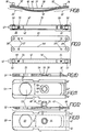
- the corner deflection 10 comprises an angular cover rail 11, which covers the groove in the corner region of a window or door leaf, in each of which a locking or control linkage is arranged, which is the one handle diverting coming movement from one side of the wing to the other.
- a flexible band 20 is used to transmit these movements, which can be moved in an angularly curved guide channel 12, the cross-sectional profile of which, shown in enlarged form, can be seen from FIGS. 2 and 3.
- connecting rod end pieces 17 are connected via rivets, which in the exemplary embodiment shown in FIG. 1 are an integral part of the corner deflection 10 and to which via known coupling pieces the drive rods of the locking and control linkage, not shown, are each connected.
- the connecting rod of the closing linkage could be connected to the band 20.
- the guide channel 12 has the C-profile shown in FIG. 2, the special feature of which is the two U-shaped longitudinal edges 18 which have a predetermined clear U-height 19. These U longitudinal edges 18 are connected to one another by the channel base 30, which is provided on the inside with a longitudinal dent 31 for reasons of stiffening or for the purpose of receiving protruding ends of a head of the rivet 16. For manufacturing reasons, the clear U-height 19 in the guide channel 12 cannot be made arbitrarily small.
- the flexible band 20 is designed in a special way. At its core, it comprises a single metallic lamella 25, which is formed from a steel strip of approximately 0.25 mm. In the end sections 22, as shown in FIG. 5, the lamella 25 is provided with a push-through hole 26 for the rivet 16 already mentioned and with one or more openings 27. This lamella 25 is also provided, at least on a lamella side 23 lying towards the inside of the angle, as shown in FIG. 6, with an applied covering 28 made of plastic, which curves concavely in the arch transition 13. This covering should always be referred to as inner covering 28 below.
- the opposite lamella side 24, which in the case of assembly points outwards against the corner point 15 of FIG. 1, as shown in FIGS. 2 and 6, is here provided with a coating 29 which curves convexly in the arch transition and therefore follows is always referred to as the outer covering 29.
- the two coverings 28, 29 all have a different layer thickness 32, 33, as can be seen from FIGS. 2, 3 and 6.
- the layer thickness 32 is less on the inside than the outer layer thickness 33.
- the outer layer thickness 33 will be chosen to be as small as possible.
- the layer thicknesses 32, 33 already change in the longitudinal course of the strip in the exemplary embodiment shown. It can thus be seen that both layer thicknesses initially grow in the end section 22 of the band 20, specifically in the outer covering 29 on a large layer thickness 33 'which can be seen in FIG the entire height in a corresponding receptacle 35 of this outer covering 29.
- This layer thickness increase 33 ' only results, as shown in FIG. 3, in the central zone of the strip 20, because there the space given by the mentioned longitudinal dent 31 is also filled. 3, the aforementioned layer thickness 33 is retained in the region of the U longitudinal edges 18 of the guide channel 12.
- the thickness ratios are formed in the inner covering 28 in a similar manner, as can also be seen from FIGS. 6 and 3.
- a constant thickness 32 of the inner covering in the end section 22 of the band 20 in the area of the two U longitudinal edges 18, but in the central zone, as can be seen in the area of the C opening 37 of the channel cross section 12 shown in FIG. 2, a larger inner layer thickness 32 'can be provided, which protrudes more or less into the C-opening 37 and out of it finally in the end region 21 with a maximum layer thickness 32 ".
- This end layer thickness 32" is produced by a shoulder 38 at the end 21 of the band 20, which ensures the correct reception of a thickened shaft piece 39 of the rivet 16, which ensures the perfect transmission of force between the drive rods 17 and the band 20.
- These thickenings 32, 32 ", 33 ' are advantageous in this area because, when the corner deflection 10 is used as intended, these end sections 22 no longer reach the area of the arch transition 13 of the guide channel 12 and therefore need not be particularly flexible higher layer thicknesses is therefore an advantageous Ver to achieve stiffness of the band in these end sections 22.
- these end sections 22 can also be passed easily through the arch transition 13 of the channel 12 for assembly purposes when the band 20 is introduced into the guide channel, they are expediently provided with interruptions in their layer thickness, which are formed here as transverse grooves 40 in the inner lining 28, which in their groove depth almost down to the inner lamella side 23, as can be seen from FIG. 6.
- transverse grooves 40 would advantageously be provided in the concave inner lining 28 of the band 20, because compression of a material with a greater layer thickness is difficult. If necessary, such interruptions in the layer thickness could of course also be provided in the outer covering 29, which will occur in particular if greater layer thicknesses occur there, which disturb the flexibility of the band 20. Such transverse grooves 40 are introduced more or less deeply into the covering 28 or 29. Their number, distribution and spacing sequence depend on the layer thickness and on the desired flexibility of the band 20 in the respective area.
- the mentioned transverse grooves 40 are only provided in the shoulder 38, which extends over the width of the thickened island 41 in the end section 22 of the band 20, which lies in the longitudinal central zone of the band and the two, in the U- Leaving longitudinal edges 18 border areas 42 unaffected.
- the lamella 25 is not arranged exactly in the middle of the stretched band. In no way does this need to take place uniformly over the entire length of the band 20. It is therefore expedient, for the reasons mentioned above, to choose the inner layer thickness 32 in the flexible middle piece 34 to be greater than the outer layer thickness 33, while these coverings 28, 29 in the end section 22 and in particular at the connection end 21 are dimensioned in opposite directions to one another, namely in the outer cover 29 more than in the inner layer 28, because the rivet head 36 mentioned is thereby easier to arrange and, moreover, in the initial state, the lamella 23 already has a pre-curvature within the covering, which in use is then only increased by the arch transition 13 in accordance with the curvature there.
- the covering can be applied to the lamella 25 in various ways, each of which has its own particular advantages.
- openings 27 ensure the material bridges between the two linings 28, 29 shown in FIG. 6 because the material can pass through the openings 27 mentioned in the lamella 25 during the encapsulation.
- openings 26 could be provided in large numbers and arranged in any distribution. They create a material connection between the two coverings.
- outer layers are applied to the two surface sides 23, 24 of the lamella by gluing or welding.
- Such outer layers could also be produced from a film by punching, where the end-side thickenings are subsequently formed by welding deformations.
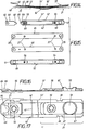
- a flexible band 50 which forms an assembly unit consisting of four layers, which, as shown in FIG. 9, consists of two prefabricated plastic outer layers 51, 52 and an inner pair of inner plates 45, 46.
- the lamellae 45, 46 have the hole 26 already mentioned for a rivet 16 indicated in its position in FIG. 8, which may initially be missing in the assembly unit 50.
- the plastic tongues 51, 52 have corresponding, albeit widened, holes 53.
- the lamellae 45, 46 also have the opening 27 already mentioned.
- the longitudinal spacing of the two openings 27 in the two lamellae 45, 46 is selected to be different by a few tenths of a millimeter in order to to produce the pre-curvature of the band which can be seen in FIG. 8 and which also includes the two plastic tongues 51, 52 in the assembly unit 50. This is due to the fact that the two tongues 51, 52 have male and female locking elements 54, 55 which are arranged in a corresponding length coordination to one another and which engage with one another in the case of assembly.
- the male-shaped closure element 54 comprises a cylindrical shaft 56, which is threaded through the openings 27 of the inner lamellae 45, 46 and fixes them in position relative to one another. At the end of the shaft there is a closing head 57 which, with elastic deformation, engages in a closing opening 58 in the matrix-shaped closure elements 55 of the plastic tongue 51 lying on the other surface side of the band 50. In addition to the closing opening 58 there is also an enlarged receptacle 59 which, in the event of a coupling, receives the closing head 57 of the male-shaped closure element 54.
- the plastic tongues 51, 52 are provided with thickened end regions 22, which assume the stiffening functions already mentioned men and are also limited here to a central zone 41 which leaves stepped thinner edge regions 42 on both sides. These have the functions already mentioned in the first exemplary embodiment.
- the thickening 22 of the tongue 51 lying on the inside of the angle has a greater thickness 32 'than the thickness 33' of the other plastic tongue 52.
- the plastic tongues 51, 52 have a continuous longitudinal strip 47 on their respective outwardly facing surfaces, on both sides of which the edge regions 42 pass because the width of this longitudinal strip 47 corresponds to the width of the aforementioned central zone 41 of the thickening 22 is limited. This results in the heel height 69 between 47 and 42 that can be seen in FIG. 12.
- the prepared assembly unit 50 After its assembly due to the closure elements 54, 55, the prepared assembly unit 50 is present, which can be easily threaded through the guide channel 12 shown in FIG. 1.
- both bands 50, 50 ' that the tongues 51, 51', 52 are produced in an injection mold from castable plastics.
- several of these tongues are produced side by side in the tool and are thus initially connected by means of sprue bars, which are cut off when the tongues are later separated.
- These sprue bars are provided at the attachment points 68, where they are cut off when the tongues are separated, so that, so that no protruding edges are formed, there are edge recesses which can be seen at these attachment points 68 in the figures.
- the feeds of the plastic are in the region of the end-side thickenings 21, which is why relatively large spaces are available in the injection mold here, which ensure good ductility of the pourable plastic.
Abstract
Description
Die Erfindung bezieht sich auf eine Eckumlenkung zum Kuppeln der längsbeweglichen Treibstangen von zwei zueinander im Winkel angeordneten Verschluss- und Steuergestängen an Fenstern, Türen od. dgl. Diese Eckumlenkungen bestehen aus einem winkelförmigen Führungskanal, der im Eckbereich eines Fenster- oder Türflügels angebracht wird und im Winkelscheitel einen Bogenübergang aufweist. Der Führungskanal, der einen 'C-förmigen Profilquerschnitt aufweisen kann, nimmt ein biegsames Band auf, welches beidendig an die Treibstangen der zu kuppelnden Gestänge angeschlossen ist, weshalb in der Regel Löcher für eine Annietbefestigung vorgesehen sind. Eine Eckumlenkung dieser Art ist durch die DE-B Nr. 2941631 bekannt. Mitdieser Eckumlenkung ist es möglich, die von dem einen Gestänge kommenden Zug- oder Druckkräfte auf das andere Gestänge zu übertragen. Die Kräfte gehen von einer Handhabe aus, die an einer Seite des Flügels angebracht ist, vollführen durch diese Kraftübertragung Steuer- und Verschlusswirkungen an anderen Stellen des Flügels.The invention relates to a corner drive for coupling the longitudinally movable connecting rods of two mutually angled locking and control linkages on windows, doors or the like. These corner drives consist of an angular guide channel, which is attached in the corner area of a window or door leaf and in Angle apex has an arch transition. The guide channel, which can have a 'C-shaped profile cross section, receives a flexible band which is connected at both ends to the drive rods of the rods to be coupled, which is why holes are generally provided for an attachment to rivets. A corner deflection of this type is known from DE-B No. 2941631. With this corner deflection, it is possible to transmit the tensile or compressive forces coming from one linkage to the other linkage. The forces emanate from a handle attached to one side of the wing and carry out control and locking effects at other points of the wing through this force transmission.
Als biegsames Band verwendet man im Stand der Technik zahlreiche übereinandergelegte Blattfedern, die kostenaufwendig herzustellen sind. Vernietet man die Blattfedern endseitig miteinander vor ihrer Montage im Führungskanal, so erfordert dies schon bei dieser Vorfertigung die Anwendung einer teuren Nietmaschine und den Einsatz besonders geschulter Arbeitskräfte. Die Durchfädelung dergenieteten Enden durch den Führungskanal ist auch schwergängig. Verzichtet man auf die Nietverbindung am einzuführenden Ende, so blättert das Paket aus Blattfedern auf und erschwert die Montagearbeit. Die zahlreichen Blattfedern sind erforderlich, um die lichte Höhe im Profil des Führungskanals auszufüllen, weil es sonst bei der Übertragung von Druckkräften zu einer wellenförmigen Deformation der Blattfedern kommt, die Betriebsstörungen hervorruft und die Lebensdauer der Eckumlenkung herabsetzt. Zur Kraftübertragung könnte man zwar mit weniger Blattfedern auskommen, doch ist es aus fertigungstechnischen Gründen nicht möglich, die lichte Höhe des Führungskanals auf preisgünstige Weise extrem niedrig auszubilden, denn beim Biegevorgang des Führungskanals würde sich das Führungsprofil im Bereich des Biegescheitels zu stark verringern und die Längsverschiebung des Bandes an dieser Stelle erschweren. Andererseits ist es auch nicht möglich, die Stärke der einzelnen Blattfedern zu erhöhen, um auf diese Weise mit weniger Blattfedern den Führungskanal auszufüllen. Die Lebensdauer eines biegsamen Bandes hält nämlich einer beträchtlich geringeren Anzahl von Lastwechselspielen statt, wenn die Stärke der dabei verwendeten Blattfedern erhöht wird.In the prior art, a flexible band uses numerous superimposed leaf springs which are expensive to produce. If the leaf springs are riveted together at the ends before they are assembled in the guide channel, this requires the use of an expensive riveting machine and the use of specially trained workers in this prefabrication. Threading the riveted ends through the guide channel is also difficult. If you do not use the riveted connection at the end to be inserted, the package of leaf springs will open and complicate the assembly work. The numerous leaf springs are required to fill the clear height in the profile of the guide channel, because otherwise there is a wave-shaped deformation of the leaf springs during the transmission of pressure forces, which causes malfunctions and reduces the lifespan of the corner drive. Although fewer leaf springs could be used for power transmission, it is not possible for manufacturing reasons to make the clear height of the guide channel extremely low in an inexpensive way, because during the bending process of the guide channel the guide profile in the area of the bending vertex would decrease too much and the longitudinal displacement of the tape at this point complicate. On the other hand, it is also not possible to increase the strength of the individual leaf springs in order to fill the guide channel with fewer leaf springs. The lifespan of a flexible band takes a considerably smaller number of load cycles if the strength of the leaf springs used is increased.
Der Erfindung liegt die Aufgabe zugrunde, eine leichtgängige, betriebssichere Eckumlenkung der im Gattungsbegriff genannten Art zu entwickeln, welche die einander scheinbar widersprechenden Forderungen nach preisgünstiger Herstellung einerseits und hoher Lebensdauer der Eckumlenkungen andererseits erfüllt.The invention has for its object to develop a smooth, reliable corner drive of the type mentioned in the generic term, which meets the apparently contradicting demands for inexpensive manufacture on the one hand and long life of the corner drives on the other.
Dies wird erfindungsgemäss dadurch erreicht, dass das biegsame Band höhenschichtweise aus artverschiedenen Werkstoffen besteht, nämlich einer oberen und unteren Aussenschicht aus Kunststoff einerseits und wenigstens einer dazwischenliegenden Innenlamelle aus Metall andererseits, wobei die beiden Aussenschichten die restliche lichte Höhe des Führungskanals über der Innenlamelle spielfrei ausfüllen, die Innenlamelle in den Endbereichen des Bandes mindestens einen Durchbruch zum Anbinden der oberen Aussenschicht an die untere aufweist und eine vorgefertigte Montageeinheit des Bandes bildet und die Endbereiche der Aussenschichten, die bei bestimmungsgemässem Gebrauch des Bandes im Führungskanal gesteckt bleiben, verdickt ausgebildet sind. Es gibt hierzu grundsätzlich zwei Ausführungsmöglichkeiten, von denen jede ihre besonderen Vorteile hat.This is achieved according to the invention in that the flexible band consists of different layers of material, namely an upper and lower outer layer made of plastic on the one hand and at least one intermediate inner lamella made of metal on the other hand, the two outer layers filling the remaining clear height of the guide channel above the inner lamella without play, the inner lamella in the end regions of the band has at least one opening for connecting the upper outer layer to the lower one and forms a prefabricated assembly unit of the band and the end regions of the outer layers, which remain inserted in the guide channel when the band is used as intended, are thickened. There are basically two options for this, each with its own particular advantages.
Fertigungsmässig einfach ist es, die Aussenschichten aus Kunststoffbelägen zu bilden, welche auf einer einzigen Innenlamelle beidflächenseitig aufgebracht sind, zum Beispiel durch Umspritzen, wobei die Kunststoffmassen die Lamellendurchbrüche durchsetzen. Obwohl man hier mit einer einzigen Lamelle auskommt, brauchen die Forderungen an die Höhe des Führungskanals nicht überspitzt zu werden, vielmehr kann hierzu ein fertigungstechnisch bequem beherrschbares Höhenmass verwendet werden, das eine hohe Lebensdauer gewährleistet. Das Restmass des Führungskanals ist von den beidflächenseitig vorgesehenen Belägen ausgefüllt. Die Innenlamelle braucht nicht mehr aus veredeltem, nicht korrodierendem Werkstoff, wie rostfreiem Stahl, gebildetzu sein, denn der aufgebrachte Belag kapselt sie ein.In terms of production, it is simple to form the outer layers from plastic coverings, which are applied to both sides of a single inner lamella, for example by extrusion coating, the plastic masses penetrating the lamella openings. Although one single slat is sufficient here, the requirements for the height of the guide channel need not be exaggerated, but rather a height dimension that can be manufacured in terms of production technology can be used, which ensures a long service life. The remaining dimensions of the guide channel are filled with the coverings provided on both sides. The inner lamella no longer has to be made of refined, non-corrosive material, such as stainless steel, because the applied covering encapsulates it.
Eine andere Möglichkeit, die sich durch besondere Flexibilität und Leichtgängigkeit des Bandes auszeichnet, besteht darin, die beiden Aussenschichten aus je einer vorgefertigten Kunststoffzunge zu bilden. Diese kann zwar nach Art des Belages ganzflächig mit der dazwischenliegenden Innenlamelle verbunden sein, doch ist es günstiger, die Kunststoffzungen auf ihren gegeneinanderweisenden Innenflächen mit Anformungen zu versehen, die - im Montagefall - Durchbrüche eines dazwischenliegenden Innenlamellenpaares durchgreifen und die Lamellen zueinander sowie bezüglich der Zungen in ihrer Querlage und in ihrer eine Vorkrümmung des Bandes bestimmenden Längslage ausrichten sowie zusammenhalten. Die Anformungen können zwar durch Schweissverbindungen od. dgl. diese Endverbindung erzeugen, doch empfiehlt es sich, die Anformungen an der einen Kunststoffzunge als patrizenförmige Verschlusselemente auszubilden, welche - im Montagefall - durch die Durchbrüche des Innenlamellenpaares hindurchgefädelt sind und mit matrizenförmigen Verschlusselementen an der anderen Kunststoffzunge in Eingriff stehen. Man gewinnt hierdurch eine Montageeinheit, weil die Enden des aus an sich getrennten mehrschichtigen Teilen gebildeten Bandes durch Werkstoffverbindungen der Aussenschichten selbst miteinander zu einer gemeinsam durch den Führungskanal hindurchfädelbaren Gebilde vereinigt sind. Die Aussenschichten sind an ihren Führungsstellen so abgestimmt, dass die lichte Weite des Führungskanals spielfrei ausgefüllt ist und daher ein Hubverlust nicht mehr feststellbar ist, der sich bisher dadurch bemerkbar machte, dass eine Bewegung am abtriebseitigen Ende der Eckumlenkung erst nach Aufwand einer gewissen Hubstrecke des antriebseitigen Endes der Eckumlenkung auftrat. Wegen der günstigen Reibungseigenschaften des Kunststoffs der Aussenschichten bezüglich des Führungskanals kann nämlich die Führungspassung sehr eng ausfallen und durch die Spritzherstellung der Aussenschichten exakt eingestellt werden.Another possibility, which is characterized by the flexibility and smoothness of the belt, is to form the two outer layers from a prefabricated plastic tongue. Although this can be connected over the entire surface to the inner lamella in between, depending on the type of covering, it is cheaper to provide the plastic tongues on their mutually facing inner surfaces with projections which - in the case of assembly - penetrate through openings of an inner lamella pair in between and the lamellae to one another and with respect to the tongues in align and hold together in their transverse position and in their longitudinal position determining a pre-curvature of the band. The projections can produce this end connection by means of welded connections or the like, but it is advisable to design the projections on one plastic tongue as male-shaped closure elements which - in the case of assembly - are threaded through the openings in the pair of inner plates and with matrix-shaped closure elements on the other plastic tongue are engaged. This results in an assembly unit because the ends of the multilayer, which is separate per se Parts of the band formed by material connections of the outer layers themselves are combined to form a structure which can be threaded through the guide channel. The outer layers are coordinated at their guide points in such a way that the clear width of the guide channel is filled without play and therefore a stroke loss can no longer be determined, which was previously noticeable in the fact that a movement at the output-side end of the corner deflection only takes a certain amount of stroke on the drive side End of the corner deflection occurred. Because of the favorable friction properties of the plastic of the outer layers with respect to the guide channel, the guide fit can be very narrow and can be set precisely by the injection molding of the outer layers.
Die endseitigen Verdickungen der Aussenschichten sorgen zunächst dafür, dass in dem für die Anschlüsse der Treibstangen befindlichen Bereich Versteifungen erzielt werden, ohne dass dies auf die zu biegenden dazwischenliegenden mittleren Abschnitte des Bandes einen nachteiligen Einfluss hat. Ausserdem lassen sich durch diese Verdickungen bei der Spritzgussherstellung der Zungen die Kunststoffmassen gut leiten, um die patrizenförmigen und matrizenförmigen Anformungen zur gegenseitigen Kupplung einwandfrei ausführen zu können. Es wird hier auch Werkstoff für etwaige Schweissverbindungen bereitgehalten. Die Verdickungen sorgen auch für definierte Abstandslagen der anzuschliessenden Treibstangen bezüglich des Bandes. Zur einwandfreien Spritzgussherstellung einer Aussenschicht empfiehlt es sich, einen durchlaufenden Längsstreifen in den Aussenschichten vorzusehen, dem gegenüber die an Leitflächen des Führungskanals längsverschiebbaren Randbereiche dickenmässig abgesetzt sind. Im Bereich der endseitigen Verdickungen sind auch die Angussstege vorgesehen, mit welchen nebeneinander im Spritzgiesswerkzeug hergestellte Aussenschichten aneinander hängen.The end thickenings of the outer layers initially ensure that stiffening is achieved in the area for the connections of the drive rods, without this having an adverse effect on the intermediate middle sections of the band to be bent. In addition, these thickenings in the injection molding of the tongues allow the plastic materials to be conducted well in order to be able to carry out the male and female moldings for mutual coupling without any problems. There is also material for any welded connections. The thickenings also ensure defined spacing of the connecting rods to be connected with respect to the belt. For the perfect injection molding of an outer layer, it is advisable to provide a continuous longitudinal strip in the outer layers, against which the edge regions that are longitudinally displaceable on guide surfaces of the guide channel are offset in terms of thickness. In the area of the end-side thickenings, the sprue bars are also provided, with which outer layers produced next to one another in the injection molding tool hang together.
Das eine Ende der Aussenschicht kann gegenüber dem Bandende zurückgesetzt sein, so dass in diesem Endabschnitt die darunterliegende Lamellenfläche freigelegt ist, um ein Verstärkungsplättchen aufzunehmen, welches die Befestigungsstelle für die anzuschliessende Treibstange stabilisiert. In diesem Fall empfiehlt es sich, das Stirnende der zurückgesetzten Aussenschicht mit einer Tasche auszubilden, die zur Aufnahme des Steckendes dieses Verstärkungsplättchens dient. Das Steckende wird zweckmässigerweise mit einer pfeilförmigen Umrissverjüngung versehen. Dadurch ist eine Verbindung zwischen dem Verstärkungsplättchen und der Aussenschicht erreicht, die zu der späteren Nietverbindung des Verstärkungsplättchens am Band hinzukommt. Das Verstärkungsplättchen ist also an zwei Stellen festgelegt und daher verdrehungssicher, weshalb keine Schwierigkeiten beim Betrieb im Führungskanal entstehen.One end of the outer layer can be set back with respect to the end of the strip, so that in this end section the underlying lamella surface is exposed in order to receive a reinforcement plate which stabilizes the fastening point for the connecting rod to be connected. In this case, it is advisable to form the front end of the recessed outer layer with a pocket that serves to receive the plug end of this reinforcement plate. The plug end is expediently provided with an arrow-shaped taper. This achieves a connection between the reinforcement plate and the outer layer, which is added to the subsequent rivet connection of the reinforcement plate on the belt. The reinforcement plate is thus fixed in two places and therefore secure against rotation, which is why there are no difficulties in operation in the guide channel.
Der Führungskanal braucht auch nicht aus kostspieligem Messing hergestellt zu sein, um bei der Erfindung eine gute Gleitfähigkeit zu begründen. Die aus Kunststoff gebildete Aussenschicht besorgt das von selbst, weshalb man zur Herstellung des Führungskanals stahl- oder messingplattierten Stahl verwenden kann, was wesentlich preiswerter ist. Damit ist auch die weitere Verarbeitung des Führungskanals vereinfacht, weil er sich an einem Deckwinkel besser anschweissen !ässt, der den Führungskanal zu der Eckumlenkung vervollständigt. Die Dicke der Aussenschichten kann, abgesehen von den ohnehin verstärkten Endbereichen, auch im übrigen Teilstück des Bandes unterschiedlich ausgebildet sein und auch die dem Winkelinneren zugekehrte Aussenschicht dicker als die gegenüberliegende Aussenschicht ausgebildet sein. Die Anwendung dieser Massnahmen hängt vom Betriebsfall ab.The guide channel also need not be made of expensive brass in order to establish good sliding properties in the invention. The plastic outer layer takes care of that, which is why steel or brass-clad steel can be used to produce the guide channel, which is much cheaper. This also simplifies the further processing of the guide channel because it can be welded better to a cover bracket that completes the guide channel for the corner deflection. The thickness of the outer layers, apart from the already reinforced end regions, can also be designed differently in the remaining part of the band and the outer layer facing the inside of the angle can also be thicker than the opposite outer layer. The application of these measures depends on the operating case.
Weitere Massnahmen und Vorteile der Erfindung sind aus den Ansprüchen und der nachfolgenden Beschreibung und den Zeichnungen ersichtlich. In den Zeichnungen ist die Erfindung in mehreren Ausführungsbeispielen dargestellt. Es zeigen:
- Fig. 1 in perspektivischer Darstellung eine Eckumlenkung nach der Erfindung,
- Fig. 2 und 3 vergrösserte Querschnittansichten dieser Eckumlenkung längs der angedeuteten Schnittlinien 11-11 im Bereich des Bogenübergangs, wo die weiter wegliegende Deckschiene nicht mit dargestellt ist, bzw. llI-IIl im Bereich des Schenkels, wo ein erstes Ausführungsbeispiel des Bandes gezeigt ist,
- Fig. 4 die Draufsicht auf das biegsame Band dieser Ausführung,
- Fig. 5 die Draufsicht auf eine im Inneren dieses Bandes befindliche metallische Innenlamelle,
- Fig. 6 und 7 in starker Vergrösseru ng den Längsschnitt bzw. die Draufsicht auf den Endbereich dieses Bandes,
- Fig. 8 in Seitenansicht eine Montageeinheit eines biegsamen Bandes einer weiteren Ausführungsform,
- Fig. 9 in Draufsicht die einzelnen Bestandteile der Montageeinheit von Fig. 8,
- Fig. 10 und 11 eine teils längsgeschnittene Seitenansicht bzw. Draufsicht auf die obere Aussenschicht der Montageeinheit von Fig. 8,
- Fig. 12 und 13 die entsprechende längsgeschnittene Seitenansicht und Draufsicht auf die untere Aussenschicht der Montageeinheit von Fig. 8,
- Fig. 14 in Seitenansicht die Montageeinheit eines erfindungsgemässen biegsamen Bandes einer weiteren Ausführungsform,
- Fig. 15 die Bestandteile der Montageeinheit von Fig. 14, und
- Fig. 16 und 17 in starker Vergrösserung die teils längsgeschnittene Seitenansicht und Draufsicht auf die beiden Endbereiche der obersten Aussenschicht des Bandes von Fig. 14.
- 1 is a perspective view of a corner drive according to the invention,
- 2 and 3 enlarged cross-sectional views of this corner deflection along the indicated cutting lines 11-11 in the area of the arch transition, where the more distant cover rail is not shown, or III-IIl in the area of the leg, where a first embodiment of the band is shown,
- 4 is a top view of the flexible band of this embodiment,
- 5 is a top view of a metallic inner lamella located inside this band,
- 6 and 7 in large enlargement the longitudinal section or the top view of the end region of this band,
- 8 is a side view of an assembly unit of a flexible band of a further embodiment,
- 9 is a plan view of the individual components of the assembly unit of FIG. 8,
- 10 and 11 is a partially longitudinally sectioned side view and plan view of the upper outer layer of the assembly unit of Fig. 8,
- 12 and 13, the corresponding longitudinal sectional side view and top view of the lower outer layer of the mounting unit of Fig. 8,
- 14 is a side view of the assembly unit of a flexible band according to the invention of a further embodiment,
- Fig. 15 shows the components of the assembly unit of Fig. 14, and
- 16 and 17 in a large enlargement the partly longitudinally sectioned side view and top view of the two end regions of the uppermost outer layer of the band from FIG. 14.
Die Eckumlenkung 10 umfasst eine winkelförmige Deckschiene 11, die im Eckbereich eines Fenster- oder Türflügels die Nut abdeckt, in welcher jeweils ein Verschluss- oder Steuergestänge angeordnet ist, welches die von einem Handgriff kommende Bewegung von einer Seite des Flügels auf die andere umlenkt. Zur Übertragung dieser Bewegungen dient ein biegsames Band 20, welches in einem winkelförmig gebogenen Führungskanal 12 bewegbar ist, dessen Querschnittsprofil, in Vergrösserung dargestellt, aus Fig. 2 bzw. 3 zu erkennen ist.The
Während die Deckschiene 11 mit ihren beiden Winkelschenkeln bis zu einem scharfen Eckpunkt 15 durchfäuft, besitzt der Führungskanal in seinem Mittelstück einen Bogenübergang 13 mitgegebenem Krümmungsradius, wo sich der Führungskanal 12 von den Winkelschenkeln der Deckschiene 11 abhebt, weshalb bei der Querschnittsdarstellung von Fig. 2 die weiter wegliegende Deckschiene im Bereich des Eckpunktes 15 nicht mit dargestellt zu werden braucht. Die sich beidseitig dieses Bogenübergangs 13 anschliessenden Schenkel 14des Führungskanals 12 sind gestreckt und durch Punktschweissen od. dgl. fest mit den Winkelschenkeln der Deckschiene 1 jeweils verbunden. Dies ist aus der Schnittsdarstellung von Fig. 3 zu erkennen.While the
Im Endbereich 21 des Bandes 20, der in Fig. 4, 6 und 7 näher gezeigt ist, sind über Niete 16 Treibstangenendstücke 17 angeschlossen, die im dargestellten Ausführungsbeispiel von Fig. 1 fester Bestandteil der Eckumlenkung 10 sind und an welche über an sich bekannte Kupplungsstücke die Treibstangen der nicht näher gezeigten Verschluss- und Steuergestänge jeweils angeschlossen sind. In manchen Anwendungsfällen könnte anstelle des eckumlenkseitigen Treibstangenendstückes 17 gleich die Treibstange des Verschlussgestänges an das Band 20 angeschlossen sein.In the
Der Führungskanai 12 hat das aus Fig. 2 ersichtliche C- Profil, dessen Besonderheit in den beiden U-förmigen Längsrändern 18 besteht, die eine vorgegebene lichte U-Höhe 19 aufweisen. Diese U-Längsränder 18 sind vom Kanalboden 30 miteinander verbunden, der aus Versteifungsgründen oder zwecks Aufnahme herausstehender Enden eines Kopfes des Niets 16 innenseitig mit einer Längsdelle 31 versehen ist. Aus fertigungstechnischen Gründen lässt sich die lichte U-Höhe 19 im Führungskanal 12 nicht beliebig klein gestalten.The
Das biegsame Band 20 ist in besonderer Weise ausgebildet. Es umfasst im Kern eine einzige metallische Lamelle 25, die aus einem Stahlband von etwa 0,25 mm gebildet ist. In den Endabschnitten 22 ist, wie Fig. 5 verdeutlicht, die Lamelle 25 mit einem Durchsteckloch 26 für den bereits erwähnten Niet 16 sowie mit einem oder mehreren Durchbrüchen 27 versehen. Diese Lamelle 25 ist ferner zumindest auf einer zum Winkelinneren hin liegenden Lamellenseite 23, wie Fig. 6 verdeutlicht, mit einem aufgebrachten Belag 28 aus Kunststoff versehen, der sich im Bogenübergang 13 konkav krümmt. Dieser Belag soll nachfolgend stets Innenbelag 28 genannt werden.The
Im vorliegenden Fall ist auch die gegenüberliegende Lamellenseite 24, die im Montagefall nach aussen, gegen den Eckpunkt 15 von Fig. 1 weist, ausweislich der Fig. 2 und 6, hier mit einem Belag 29 versehen, der sich im Bogenübergang konvex krümmt und daher nachfolgend stets als Aussenbelag 29 bezeichnet wird. Die beiden Beläge 28,29 besitzen durchwegs eine zueinander unterschiedliche Schichtstärke 32, 33, wie aus den Fig. 2, 3 und 6 zu erkennen ist.In the present case, the
Im dargestellten Ausführungsbeispiel von Fig. 4 und 6 ist im Mittelstück 34 des Bandes 20 die Schichtdicke 32 innen geringer als die äussere Schichtdicke 33 ausgebildet. Es wäre allerdings zweckmässig, zur Erzielung einer Krümmung mit einem möglichst grossen Radius zumindest in jenem Bereich des Mittelstückes 34, welches bei der Betätigung der Eckumlenkung jeweils die Krümmung im Bogenübergang 13 des Führungskanals 12 ausführen muss, mit einer möglichst grossen Innenschichtdicke 32 auszubilden, so dass die Lamelle 25 möglichst nahe an die konvexe Aussenseite des Bandes 20 gelangt. Man wird dabei die Aussenschichtdicke 33 möglichst gering wählen.In the exemplary embodiment shown in FIGS. 4 and 6, in the
Die Schichtdicken 32,33 ändern sich im Längsverlauf des Bandes bereits im dargestellten Ausführungsbeispiel. So ist zu erkennen, dass beide Schichtdicken zunächst im Endabschnitt 22 des Bandes 20 anwachsen, und zwar im Aussenbelag 29 auf einer aus Fig. 6 ersichtlichen grossen Schichtdicke 33', die es gestattet, den dort strichpunktiert angedeuteten Nietkopf 36 des Befestigungsglieds 16 möglichst in seiner ganzen Höhe voll in eine entsprechende Aufnahme 35 dieses Aussenbelags 29 aufzunehmen. Diese Schichtdikkenerhöhung 33' ergibt sich aber nur, wie Fig. 3 verdeutlicht, in der Mittelzone des Bandes 20, weil dort der durch die erwähnte Längsdelle 31 gegebene Freiraum mit ausgefüllt wird. Im Bereich der U-Längsränder 18 des Führungskanals 12 bleibt die vorerwähnte Schichtdicke 33 ausweislich der Fig. 3 erhalten.The layer thicknesses 32, 33 already change in the longitudinal course of the strip in the exemplary embodiment shown. It can thus be seen that both layer thicknesses initially grow in the
In ähnlicher Weise sind die Dickenverhältnisse im Innenbelag 28 ausgebildet, wie ebenfalls aus Fig. 6 und 3 hervorgeht. Auch hier ist im Endabschnitt 22 des Bandes 20 im Bereich der beiden U-Längsränder 18 eine gleichbleibende Dicke 32 des Innenbelags gegeben, jedoch kann in der Mittelzone, wie im Bereich der aus Fig. 2 ersichtlichen C-Öffnung 37 des Kanalquerschnitts 12 sich ergibt, eine grössere Innenschichtdicke 32' vorgesehen sein, die mehr oder weniger in die C-Öffnung 37 hinein und aus dieserschliesslich im Endbereich 21 mit einer maximalen Schichtdicke 32" herausragt. Diese Endschichtdicke 32" ist durch einen Ansatz 38 am Ende 21 des Bandes 20 erzeugt, der für eine einwandfreie Aufnahme eines verdickten Schaftstückes 39 des Nietes 16 sorgt, der für eine einwandfreie Kraftübertragung zwischen den Treibstangen 17 und dem Band 20 sorgt.The thickness ratios are formed in the
Diese Verdickungen 32, 32", 33'sind insofern in diesem Bereich vorteilhaft, weil diese Endabschnitte 22 bei bestimmungsgemässem Gebrauch der Eckumlenkung 10 in keinem Fall mehr in den Bereich des Bogenübergangs 13 des Führungskanals 12 gelangen und daher keine besondere Flexibilität aufzuweisen brauchen. Durch diese höheren Schichtdicken ist daher eine vorteilhafte Versteifung des Bandes in diesen Endabschnitten 22 zu erzielen. Damit aber diese Endabschnitte 22 zu Montagezwecken beim Einführen des Bandes 20 in den Führungskanal auch leichtgängig durch den Bogenübergang 13 des Kanals 12 hindurchführbar sind, wird man sie zweckmässigerweise mit Unterbrechungen ihrer Schichtdicke versehen, die hier als Querrillen 40 im Innenbelag 28 ausgebildet sind, die in ihrer Rillentiefe nahezu bis zu der inneren Lamellenseite 23 hinabgehen, wie aus Fig. 6 hervorgeht. Solche Querrillen 40 wären vorteilhaft in dem sich konkav krümmenden Innenbelag 28 des Bandes 20 vorgesehen, denn eine Stauchung eines Materials grösserer Schichtdicke ist schwierig. Bedarfsweise könnte man natürlich solche Unterbrechungen der Schichtdicke auch im Aussenbelag 29 vorsehen, was insbesondere dann eintreten wird, wenn dort grössere Schichtdicken auftreten, welche die Flexibilität des Bandes 20 stören. Solche Querrillen 40 werden mehr oder weniger tief in den Belag 28 bzw. 29 eingebracht. Ihre Anzahl, Verteilung und Abstandsfolge richtet sich nach der Schichtdicke und nach der gewünschten Flexibilität des Bandes 20 in dem jeweiligen Bereich. So sind ausweislich der Fig. 7 die erwähnten Querrillen 40 nur in dem Ansatz 38 vorgesehen, der sich über die Breite der verdickten Insel 41 im Endabschnitt 22 des Bandes 20 erstreckt, welche in der Längsmittelzone des Bandes liegt und die beiden, in die U-Längsränder 18 fassenden Randbereiche 42 davon unbeeinflusst lässt.These
Aus Fig. 7 ist weiterhin ersichtlich, dass die beiden Beläge an die Schmalseiten der Lamelle 25 keine oder nur äusserst geringe Schichtdicken 43 aufweisen, die auch ganz fehlen könnten, weil dadurch die Lamelle 25 sich praktisch über die gegebene ganze Profilbreite des C-Kanalquerschnitts erstrecken kann. Dadurch ist auch kein Zusammenhang der zueinander entgegengesetzt beanspruchten Beläge 28,29 auf den beiden Lamellenseiten 23, 24 gegeben.From FIG. 7 it can also be seen that the two coverings on the narrow sides of the
Wie ersichtlich ist, ist bereits im Ausführungsbeispiel die Lamelle 25 nicht genau in der Mitte des gestreckten Bandes angeordnet. Dies braucht auch keineswegs einheitlich über die ganze Länge des Bandes 20 zu erfolgen. So ist es zweckdienlich, aus den obenerwähnten Gründen im biegsamen Mittelstück 34 die Innenschichtdicke 32 grösser zur Aussenschichtdicke 33 zu wählen, während diese Beläge 28, 29 im Endabschnitt 22 und insbesondere am Anschlussende 21 in entgegengesetzter Weise zueinander dimensioniert sind, nämlich im Aussenbelag 29 stärker als im Innebelag 28, weil dadurch der erwähnte Nietkopf 36 besser anzuordnen ist und im übrigen die Lamelle 23 im Ausgangszustand bereits innerhalb des Belags eine Vorkrümmung aufweist, die im Anwendungsfall dann nur noch dem Bogenübergang 13 entsprechend der dortigen Krümmung gesteigert wird.As can be seen, already in the exemplary embodiment the
Das Aufbringen des Belags auf die Lamelle 25 kann in verschiedener Weise erfolgen, deren jede ihre besonderen Vorteile mit sich bringt.The covering can be applied to the
Eine im dargestellten Ausführungsbeispiel angewendete Möglichkeit besteht, indem man die beiden Beläge 28, 29 durch Umspritzen auf die Lamelle 25 aufbringt. Die vorerwähnten Durchbrüche 27 sorgen dabei für die aus Fig. 6 ersichtlichen Werkstoffbrücken zwischen den beiden Belägen 28, 29, weil beim Umspritzen der Werkstoff durch die erwähnten Durchbrüche 27 in der Lamelle 25 treten kann. Solche Durchbrüche 26 könnten in grösserer Anzahl vorgesehen und in beliebiger Verteilung angeordnet sein. Sie schaffen eine Werkstoffverbindung zwischen den beiden Belägen.One possibility used in the exemplary embodiment shown is by applying the two
Eine andere Möglichkeit besteht darin, die Beläge als gesonderte Aussenschichten vorzufertigen, wie sie bei den nachfolgenden beiden Ausführungsbeispielen der Fig. 8 bis 17 näher erläutert ist. Im vorliegenden Fall werden diese Aussenschichten auf die beiden Flächenseiten 23, 24 der Lamelle durch Verkleben oder Verschweissen aufgebracht. Solche Aussenschichten könnten auch durch Stanzen aus einer Folie hergestellt sein, wo die endseitigen Verdickungen durch Schweissverformungen nachträglich angeformt werden.Another possibility is to prefabricate the coverings as separate outer layers, as is explained in more detail in the following two exemplary embodiments of FIGS. 8 to 17. In the present case, these outer layers are applied to the two
Im Ausführungsbeispiel von Fig. 8 bis 13 ist ein biegsames Band 50 gezeigt, das eine Montageeinheit aus vier Schichten bildet, die ausweislich der Fig. 9 aus zwei vorgefertigten Kunststoff-Aussenschichten 51, 52 und einem dazwischenliegenden Innenlamellenpaar 45, 46 besteht. Die Lamellen 45, 46 besitzen das bereits erwähnte Loch 26 für einen in Fig. 8 in seiner Position angedeuteten Niet 16, welcher in der Montageeinheit 50 zunächst fehlen kann. Die Kunststoffzungen 51, 52 besitzen entsprechende, wenn auch demgegenüber erweiterte Löcher 53. Die Lamellen 45, 46 besitzen ferner den bereits erwähnten Durchbruch 27. Der Längsabstand der beiden Durchbrüche 27 ist in beiden Lamellen 45,46 zueinander unterschiedlich um einige Zehntel Millimeter gewählt, um bei der Montageeinheit 50 die aus Fig. 8 erkennbare Vorkrümmung des Bandes zu erzeugen, welche die beiden Kunststoffzungen 51, 52 mitumfasst. Dies kommt dadurch zustande, dass die beiden Zungen 51, 52 in entsprechender Längenabstimmung zueinander angeordnete patrizenförmige und matrizenförmige Verschlusselemente 54, 55 aufweisen, die im Montagefall miteinander in Eingriff stehen.In the exemplary embodiment from FIGS. 8 to 13, a
Das patrizenförmige Verschlusselement 54 umfasst einen zylindrischen Schaft 56, der durch die Durchbrüche 27 der Innenlamellen 45, 46 hindurchgefädelt wird und diese zueinander lagefixiert. Am Schaftende sitzt ein Schliesskopf 57, der unter elastischer Verformung in eine Schliessöffnung 58 in den matritzenförmigen Verschlusselementen 55 der auf der anderen Flächenseite des Bandes 50 liegenden Kunststoffzunge 51 eingreift. Neben der Schliessöffnung 58 liegt noch eine erweiterte Aufnahme 59, die im Kupplungsfall den Schliesskopf 57 des patrizenförmigen Verschlusselements 54 aufnimmt.The male-shaped
Die Kunststoffzungen 51, 52 sind, ähnlich wie im vorausgehenden Ausführungsbeispiel, mit verdickten Endbereichen 22 versehen, welche die bereits erwähnten Versteifungsfunktionen übernehmen und auch hier auf eine Mittelzone 41 beschränkt sind, die abgesetzte dünnere Randbereiche 42 beidseitig belässt Diese haben die breits im ersten Ausführungsbeispiel erwähnten Funktionen. Auch hier besitzt die Verdickung 22 bei der winkelinnenseitig liegenden Zunge 51 eine grössere Stärke 32', als die Dicke 33' bei der anderen Kunststoffzunge 52 beträgt. Ergänzend kommt aber noch hinzu, dass hier die Kunststoffzun- gen 51, 52 auf ihren jeweils nach aussen gekehrten Flächen einen durchlaufenden Längsstreifen 47 aufweisten, beidseitig dessen die Randbereiche 42 durchlaufen, weil die Breite dieses Längsstreifens 47 auf die Breite der vorerwähnten Mittelzone 41 der Verdickung 22 begrenzt ist. Dadurch ergibt sich die aus Fig. 12 erkennbare Absatzhöhe 69 zwischen 47 und 42.Similar to the previous exemplary embodiment, the
Nach ihrer Montage aufgrund der Verschlusselemente 54, 55 liegt die vorbereitete Montageeinheit 50 vor, die sich bequem in den aus Fig. 1 ersichtlichen Führungskanal 12 hindurchfädeln lässt.After its assembly due to the
In Fig 14 bis 17 ist ein letztes Ausführungsbeispiel eines erfindungsgemässen biegsamen Bandes 50' gezeigt, das in vielerlei Hinsicht den gleichen Aufbau und die Wirkungsweise hat, wie das vorausgehende Ausführungsbeispiel des Bandes 50 von Fig. 8 bis 13. Insoweit gilt die bisherige Beschreibung. Es sind daher zur Bezeichnung entsprechender Bauteile die gleichen Bezugszeichen verwendet. Unterschiede bestehen lediglich in folgender Hinsicht:
Das eine Ende 48 der winkelinnenseitig angeordneten Kunststoffzunge 51' ist gegenüberdem Bandende 49 zurückgesetzt, weshalb in diesem Teilstück die Lamellenfläche 63, gemäss Fig. 14, freiliegt. Nach der Montage des Bandes 50'im Führungskanal 12 wird auf das gesamte Teilstück 63ein Verstärkungsplättchen 60 aufgelegt, welches mit einemLoch 62 versehen ist, das zur Dekkung mit den bereits mehrfach erwähnten Löchern 26 desLamellenpaares Eingriff kommenden Verschlusselemente mit den Kunststoffzungen 51', 52 bilden. Hier erfolgt der Anschluss der Treibstange,und das Verstärkungsplättchen 60 stabilisiert diesen Bereich.Das Plättchen 60 ist mit einem pfeilförmig gestalteten Steckende 61 versehen, welches ineiner Tasche 64am Zungenende 48 eingeführt wird und dadurch eine zweite Lagesicherung an der Montageeinheit 50' erfährt.Diese Tasche 64 ist dadurch zustande gekommen, dass über einer U-förmigen Aussparung eine Deckwand 66 aufgebracht ist, die beim Kuppelnvon dem Steckende 61 hintergriffen wird. Das eineLoch 53 der Kunststoffzunge 51', νvo der Anschluss der zugehörigen Treibstange erfolgt, ist zur Stützung der Nietbefestigungmit einem Wulstrand 67 versehen.
- One
end 48 of the plastic tongue 51 'arranged on the inside of the angle is set back relative to theband end 49, which is why the lamella surface 63, according to FIG. 14, is exposed in this section. After the assembly of the band 50 'in theguide channel 12, areinforcement plate 60 is placed on the entire section 63, which is provided with ahole 62 which comes to cover with theholes 26 of the pair ofplates closure elements plastic tongues 51 ', 52. This is where the connecting rod is connected and thereinforcement plate 60 stabilizes this area. Theplate 60 is provided with an arrow-shapedplug end 61, which is inserted into apocket 64 at thetongue end 48 and thereby experiences a second position securing on the assembly unit 50 '. Thispocket 64 has come about in that atop wall 66 is applied over a U-shaped recess, which is engaged behind by theplug end 61 when coupling. Onehole 53 of the plastic tongue 51 ', νvo the connection of the associated drive rod takes place, is provided with abead 67 to support the rivet attachment.
Für beide Bänder 50, 50' gilt, dass die Zungen 51, 51', 52 in einem Spritzwerkzeug aus giessfähigen Kunststoffen hergestellt werden. Dazu werden mehrere dieser Zungen gleichzeitig im Werkzeug nebeneinanderliegend hergestellt und sind dadurch mittels Angussstegen zunächst verbunden, die bei späterer Vereinzelung der Zungen abgeschnitten werden. Diese Angussstege sind an den-Ansatzstellen 68 vorgesehen, wo sie bei der Vereinzelung der Zungen abgeschnitten werden, so dass, damit keine vorstehenden Kanten entstehen, es zu den an diesen Ansatzstellen 68 in den Figuren erkennbaren Randaussparungen kommt. Ausweislich der Ansatzstellen 68 befinden sich die Zuführungen des Kunststoffes im Bereich der endseitigen Verdickungen 21,-weshalb hier im Spritzwerkzeug verhältnismässig grosse Räume zur Verfügung stehen, die für gute Leitung des giessfähigen Kunststoffes sorgen. Gleiches vollzieht sich in entsprechender Weise in den längsmittig durchlaufenden Längsstreifen 47 der Zungen 51, 51', 52. Ihnen gegenüber sind nur Randbereiche 42 um den aus Fig. 12 ersichtlichen Absatz 69 dünner gemacht, um in spielfreier Passung die aus Fig. 2 ersichtliche lichte Höhe 19 des Führungskanals 12 auszufüllen.It applies to both
Claims (18)
Priority Applications (1)
| Application Number | Priority Date | Filing Date | Title |
|---|---|---|---|
| AT82102658T ATE9376T1 (en) | 1981-05-09 | 1982-03-30 | CORNER DEVICE FOR COUPLING LOCKING AND CONTROL RODS ON WINDOWS, DOORS OR. DGL. |
Applications Claiming Priority (2)
| Application Number | Priority Date | Filing Date | Title |
|---|---|---|---|
| DE3118435 | 1981-05-09 | ||
| DE3118435A DE3118435A1 (en) | 1981-05-09 | 1981-05-09 | CORNER DEFLECTION FOR COUPLING LOCKING AND CONTROL RODS TO WINDOWS, DOORS OR THE LIKE. |
Publications (3)
| Publication Number | Publication Date |
|---|---|
| EP0064595A1 EP0064595A1 (en) | 1982-11-17 |
| EP0064595B1 true EP0064595B1 (en) | 1984-09-12 |
| EP0064595B2 EP0064595B2 (en) | 1988-05-25 |
Family
ID=6131881
Family Applications (1)
| Application Number | Title | Priority Date | Filing Date |
|---|---|---|---|
| EP82102658A Expired EP0064595B2 (en) | 1981-05-09 | 1982-03-30 | Corner connection of locking and actuating bars for windows, doors or the like |
Country Status (3)
| Country | Link |
|---|---|
| EP (1) | EP0064595B2 (en) |
| AT (1) | ATE9376T1 (en) |
| DE (2) | DE3118435A1 (en) |
Families Citing this family (6)
| Publication number | Priority date | Publication date | Assignee | Title |
|---|---|---|---|---|
| AT386040B (en) * | 1983-08-13 | 1988-06-27 | Rsb Holding & Management Ag | ONE-HAND TURNTABLE FITTING FOR A WINDOW |
| FR2556400B1 (en) * | 1983-12-09 | 1986-07-18 | Ferco Int Usine Ferrures | CORNER TRANSMISSION FOR OPERATING ROD OF A WINDOW FITTING, DOOR OR THE LIKE |
| EP0173236B1 (en) * | 1984-08-22 | 1990-04-04 | Josef Oster | Window or door fitting |
| DE3545860A1 (en) * | 1985-12-23 | 1987-07-02 | Schuermann & Co Heinz | CORNER DEVICE OF A LATCH FITTING OF A WINDOW OR DOOR |
| DE9203338U1 (en) * | 1992-03-12 | 1993-07-08 | Siegenia-Frank Kg, 5900 Siegen, De | |
| IT1393807B1 (en) * | 2008-10-30 | 2012-05-11 | Gsg Int Spa | CLOSING DEVICE FOR WINDOWS. |
Family Cites Families (3)
| Publication number | Priority date | Publication date | Assignee | Title |
|---|---|---|---|---|
| DE1134295B (en) * | 1957-11-09 | 1962-08-02 | Zuendapp Werke G M B H | Cable pull for the transmission of pulling and / or pushing forces, especially for motor vehicles |
| DE2240345A1 (en) * | 1972-08-17 | 1974-02-28 | Frank Gmbh Wilh | FASTENING ELEMENT FOR WINDOWS, DOORS OR DGL. |
| DE2941631C2 (en) * | 1979-10-13 | 1985-06-20 | Siegenia-Frank Kg, 5900 Siegen | Corner drive for espagnolette fittings |
-
1981
- 1981-05-09 DE DE3118435A patent/DE3118435A1/en not_active Withdrawn
-
1982
- 1982-03-30 DE DE8282102658T patent/DE3260697D1/en not_active Expired
- 1982-03-30 AT AT82102658T patent/ATE9376T1/en not_active IP Right Cessation
- 1982-03-30 EP EP82102658A patent/EP0064595B2/en not_active Expired
Also Published As
| Publication number | Publication date |
|---|---|
| DE3260697D1 (en) | 1984-10-18 |
| DE3118435A1 (en) | 1982-12-02 |
| ATE9376T1 (en) | 1984-09-15 |
| EP0064595B2 (en) | 1988-05-25 |
| EP0064595A1 (en) | 1982-11-17 |
Similar Documents
| Publication | Publication Date | Title |
|---|---|---|
| EP0086959A1 (en) | Sealing strip with metallic reinforcement made of thermoplastic material | |
| DE19521566A1 (en) | Longitudinal guide for seat of motor vehicle | |
| EP1757838B1 (en) | Stiff back drive chain | |
| WO2004074736A1 (en) | Extendable protective covering | |
| EP0064595B1 (en) | Corner connection of locking and actuating bars for windows, doors or the like | |
| CH630713A5 (en) | Extruder structural element for the construction of walls, especially of motor vehicles | |
| DE60108638T2 (en) | DEFLECTION DEVICE FOR CONVEYORS | |
| DE102020200266B4 (en) | Sliding-rigid linear chain that can be actuated with a chain drive | |
| AT409025B (en) | CORNER DEFLECTION OF DRIVE ROD FITTINGS FOR WINDOWS, DOORS OR THE LIKE. | |
| EP0030385A1 (en) | Construction element for doors, gates or the like and process for its production | |
| DE19806727A1 (en) | Lock for windows or doors | |
| DE8208893U1 (en) | CORNER DEFLECTION FOR COUPLING LOCKING AND CONTROL RODS TO WINDOWS, DOORS OR. DGL. | |
| CH687716A5 (en) | Fitting. | |
| DE3323265C2 (en) | ||
| DE3015925A1 (en) | FRAME LATHE OF A STRAND FRAME OF A LOUNGE | |
| EP0806540A1 (en) | Slat for a leaf of a preferably up and down movable roller shutter for a gate, a door, a window or similar opening | |
| EP0384142B1 (en) | Actuating rod having configurated coupling means | |
| DE2159244C3 (en) | Corner drive for espagnolette fittings | |
| EP1223273B1 (en) | Rod coupling | |
| EP1270856B1 (en) | Fitting for locking of windows or doors | |
| EP0348605B1 (en) | Device for tilting part of a bed frame | |
| DE3439545C2 (en) | ||
| DE20304437U1 (en) | Inverted toothed chain for use in motor vehicle construction has inner link plates each manufactured by powder metallurgical process and/or forming process such as extruding or rolling | |
| DE3408838C2 (en) | ||
| DE2831652C2 (en) | Body element composed of individual wall elements |
Legal Events
| Date | Code | Title | Description |
|---|---|---|---|
| PUAI | Public reference made under article 153(3) epc to a published international application that has entered the european phase |
Free format text: ORIGINAL CODE: 0009012 |
|
| AK | Designated contracting states |
Designated state(s): AT BE DE FR GB |
|
| 17P | Request for examination filed |
Effective date: 19821019 |
|
| GRAA | (expected) grant |
Free format text: ORIGINAL CODE: 0009210 |
|
| AK | Designated contracting states |
Designated state(s): AT BE DE FR GB |
|
| PG25 | Lapsed in a contracting state [announced via postgrant information from national office to epo] |
Ref country code: FR Free format text: THE PATENT HAS BEEN ANNULLED BY A DECISION OF A NATIONAL AUTHORITY Effective date: 19840912 Ref country code: BE Effective date: 19840912 |
|
| REF | Corresponds to: |
Ref document number: 9376 Country of ref document: AT Date of ref document: 19840915 Kind code of ref document: T |
|
| REF | Corresponds to: |
Ref document number: 3260697 Country of ref document: DE Date of ref document: 19841018 |
|
| PG25 | Lapsed in a contracting state [announced via postgrant information from national office to epo] |
Ref country code: AT Effective date: 19850330 |
|
| PLBI | Opposition filed |
Free format text: ORIGINAL CODE: 0009260 |
|
| 26 | Opposition filed |
Opponent name: SIEGENIA-FRANK KG Effective date: 19850511 |
|
| EN | Fr: translation not filed | ||
| GBPC | Gb: european patent ceased through non-payment of renewal fee | ||
| PUAH | Patent maintained in amended form |
Free format text: ORIGINAL CODE: 0009272 |
|
| STAA | Information on the status of an ep patent application or granted ep patent |
Free format text: STATUS: PATENT MAINTAINED AS AMENDED |
|
| 27A | Patent maintained in amended form |
Effective date: 19880525 |
|
| AK | Designated contracting states |
Kind code of ref document: B2 Designated state(s): AT BE DE FR GB |
|
| EN3 | Fr: translation not filed ** decision concerning opposition | ||
| PG25 | Lapsed in a contracting state [announced via postgrant information from national office to epo] |
Ref country code: GB Effective date: 19881121 |
|
| PGFP | Annual fee paid to national office [announced via postgrant information from national office to epo] |
Ref country code: DE Payment date: 19920728 Year of fee payment: 11 |
|
| PG25 | Lapsed in a contracting state [announced via postgrant information from national office to epo] |
Ref country code: DE Effective date: 19931201 |