EP0063729A2 - Apparatus for the inversion and mixture of flowing materials - Google Patents
Apparatus for the inversion and mixture of flowing materials Download PDFInfo
- Publication number
- EP0063729A2 EP0063729A2 EP82103009A EP82103009A EP0063729A2 EP 0063729 A2 EP0063729 A2 EP 0063729A2 EP 82103009 A EP82103009 A EP 82103009A EP 82103009 A EP82103009 A EP 82103009A EP 0063729 A2 EP0063729 A2 EP 0063729A2
- Authority
- EP
- European Patent Office
- Prior art keywords
- guide surfaces
- flow
- tube
- pipe
- section
- Prior art date
- Legal status (The legal status is an assumption and is not a legal conclusion. Google has not performed a legal analysis and makes no representation as to the accuracy of the status listed.)
- Granted
Links
- 239000000463 material Substances 0.000 title abstract 2
- 239000000203 mixture Substances 0.000 title description 2
- 239000000126 substance Substances 0.000 claims description 4
- 238000006243 chemical reaction Methods 0.000 claims 1
- 230000002093 peripheral effect Effects 0.000 abstract 2
- 239000012530 fluid Substances 0.000 description 9
- 230000003068 static effect Effects 0.000 description 5
- 239000007787 solid Substances 0.000 description 3
- 239000003463 adsorbent Substances 0.000 description 2
- 239000003054 catalyst Substances 0.000 description 2
- 238000010586 diagram Methods 0.000 description 2
- 239000007788 liquid Substances 0.000 description 2
- 230000015572 biosynthetic process Effects 0.000 description 1
- 238000010276 construction Methods 0.000 description 1
- 230000002349 favourable effect Effects 0.000 description 1
- 239000000945 filler Substances 0.000 description 1
- 239000007789 gas Substances 0.000 description 1
Images


Classifications
-
- B—PERFORMING OPERATIONS; TRANSPORTING
- B01—PHYSICAL OR CHEMICAL PROCESSES OR APPARATUS IN GENERAL
- B01J—CHEMICAL OR PHYSICAL PROCESSES, e.g. CATALYSIS OR COLLOID CHEMISTRY; THEIR RELEVANT APPARATUS
- B01J19/00—Chemical, physical or physico-chemical processes in general; Their relevant apparatus
- B01J19/30—Loose or shaped packing elements, e.g. Raschig rings or Berl saddles, for pouring into the apparatus for mass or heat transfer
- B01J19/305—Supporting elements therefor, e.g. grids, perforated plates
-
- B—PERFORMING OPERATIONS; TRANSPORTING
- B01—PHYSICAL OR CHEMICAL PROCESSES OR APPARATUS IN GENERAL
- B01F—MIXING, e.g. DISSOLVING, EMULSIFYING OR DISPERSING
- B01F25/00—Flow mixers; Mixers for falling materials, e.g. solid particles
- B01F25/40—Static mixers
- B01F25/42—Static mixers in which the mixing is affected by moving the components jointly in changing directions, e.g. in tubes provided with baffles or obstructions
- B01F25/43—Mixing tubes, e.g. wherein the material is moved in a radial or partly reversed direction
- B01F25/431—Straight mixing tubes with baffles or obstructions that do not cause substantial pressure drop; Baffles therefor
- B01F25/4315—Straight mixing tubes with baffles or obstructions that do not cause substantial pressure drop; Baffles therefor the baffles being deformed flat pieces of material
- B01F25/43151—Straight mixing tubes with baffles or obstructions that do not cause substantial pressure drop; Baffles therefor the baffles being deformed flat pieces of material composed of consecutive sections of deformed flat pieces of material
Definitions
- the present invention relates to a device for inverting and mixing flowing substances in a tube of any cross-section with at least one mixing element, consisting of guide surfaces, through which fluid elements flowing in the tube center are transported to the outside and fluid elements flowing outside to the inside ("flow inverter").
- flow inverter a device for inverting and mixing flowing substances in a tube of any cross-section with at least one mixing element, consisting of guide surfaces, through which fluid elements flowing in the tube center are transported to the outside and fluid elements flowing outside to the inside
- flow inverter a device for inverting and mixing flowing substances in a tube of any cross-section with at least one mixing element, consisting of guide surfaces, through which fluid elements flowing in the tube center are transported to the outside and fluid elements flowing outside to the inside
- Fluid should be understood to mean liquids, gases or free-flowing solids, as well as single or multi-phase mixtures of liquid, gaseous and / or solid components.
- a mixing device which consists of a number of oppositely inclined flow channels, which are open towards each other and act in relation to the flow division similarly to the above-mentioned arrangements.
- each mixing element consisting of an even number of sector-shaped guide surfaces and optionally of boundary surfaces.
- the task of the guide surfaces is the fluid transport in the radial direction from outside to inside and from inside to outside.
- the guide surfaces represent sections of the outer surface of cones and pyramids with a tip in the tube axis, the generatrix of the cone surface with the tube axis forming a constant or radial and circumferential angle of attack from 10 ° to 70 °.
- a mixing element can, for example, only be constructed from guide surfaces without boundary surfaces, the guide surfaces either pointing inwards or outwards and the backflow not being directed, or alternating guide surfaces pointing inwards and outwards alternate in the circumferential direction.
- Boundary surfaces are either flat surfaces, which preferably extend in the axial and radial direction with their main axes, or helices around the pipe axis.
- a complete, mixture-free shifting of the entire inner region of a pipe flow ("inner flow”) to the outside and the outer area (“outer flow”) to the inside is achieved according to the invention by a device in which an inlet duct first separates the inner region of the pipe flow from the outer region, then an inlet distributor Internal flow as well as the external flow each summarizes and distributed over an even number of flow channels, each flow channel filling a sector of the free pipe cross section.
- the subsequent division of the internal flow from its channels to the outside, and the outside flow to the inside, can be effected most simply by means of a distributor which is identical to the inlet distributor and is arranged in a mirror image of this, as well as offset by a sector.
- the distributor can be constructed by a suitable arrangement of guide surfaces and boundary surfaces of the type described above.
- the device By means of the device according to the invention, a shifting of a pipe flow from the inside to the outside and from the outside to the inside is brought about in a simple manner, so that the heat transfer in wall-heated or cooled pipes is thereby substantially improved.
- the device is suitable for all traditional areas of application of static mixers. t ..
- Another advantageous area of application is pipes that are filled with a solid bed (adsorbent, catalyst, etc.) and have a large pressure loss when flowing through them.
- the device according to the invention as a filler, provides for loosening and thus for a more uniform flow as well as for a reduction in pressure loss as a result of the improvement of the wall heat transfer, without the formation of flow passages ("edge movement").
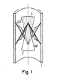
- Figure 1 shows a basic form of the device according to the invention in the cut tube in a perspective view.
- An even number of guide surfaces 2 are attached in a tube 1.
- the guide surfaces 2 consist of cutouts from the outer surface of two identical straight cones, the common axis of which Axis of tube 1 coincides.
- the generatrix of the conical surface with the tube axis form an angle of attack of preferably 25 ° to 45 °.
- the individual guide surfaces 2 are alternately inclined inwards and outwards in the manner shown and lie on the inner wall of the tube 1 with outer cut edges 3.
- the arrangement shown is symmetrical with respect to the direction of flow.
- Three baffles 9 each separate the flow from the wall and guide it inwards, three other baffles 8 guide the flow from the inside to the wall.
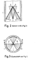
- Figures 2 and 3 show the device shown in Figure 1 in longitudinal and cross section.
- FIG. 4 A further advantageous embodiment of the device according to the invention is shown in FIG. 4.
- the guide surfaces 2 which follow one another in the circumferential direction are each shifted by a constant amount in the axial direction with the same direction of inclination.
- the outer cutting edge 3 of the guide surfaces 2 has an angle of incidence different from 90 ° with the direction of the tube axis.
- the angle of attack in the range from 45 ° to 800, the radial (outward or inward) flow direction of the guide surfaces 2 is superimposed on a component in the circumferential direction.
- the guide surfaces 2 with inner cut edges 4 can rest against a central tube 14 or be firmly connected to it, the heat transfer being improved not only to the tube 1 but also to the central tube 14 by the device according to the invention.
- FIG. 5 A further advantageous embodiment of the invention is shown in FIG. 5 in a cut-open tube in perspective, FIG. 6 in longitudinal section and FIG. 7 in cross section.
- the individual, alternating inward and outward guide surfaces 2 are separated from each other by boundary surfaces 5 over a certain area of the radius, the boundary surfaces 5 abutting lateral cutting edges 6 of the guide surfaces 2, so that flow channels are formed in which the fluid alternately follows is transported inside and outside. This avoids a flow around the web of the guide surfaces 2 in the region of the boundary surfaces 5 and improves the circulation from the inside to the outside.
- the flow diagram is outlined in FIG.
- the boundary surfaces 5 can either lie in one of their main axes parallel to the pipe axis (FIG. 5-7) or wind in the form of spirals around the pipe axis.
- the guide surfaces 2 are preferably formed from the lateral surface of straight cones or pyramids, but single or multiple curved shapes can also be used, as outlined in longitudinal section in FIG. It can also be advantageous to provide cutouts or cutouts in the guide surfaces. This applies in particular to the design of the outer cutting edge 3 and its connection to the pipe wall.
- Figure 9 shows some design options. A gap 7 on the front face of the guide surface and a stagnation area on the back of the guide surface can be avoided by a defined gap 7. In the direction of flow, successive guide surfaces 2 can either overlap with their lateral cutting edges 6 or leave a space,
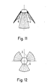
- FIGS. 11 and 12 show as an example a single element with three guide surfaces 2 in a perspective view and in a top view
- FIG. 13 shows the diagram of the nesting of these elements in longitudinal section.
- the device consists of guide surfaces 2 which guide the flow either only inwards or only outwards.
- the backflow is non-directional.
- FIG. 14 shows a corresponding example of three successive guide surface groups in the cut tube in a perspective view.
- successive guide surface groups are rotated so that blocked and unblocked pipe cross-section sectors alternate with one another.
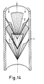
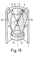
- a device according to the invention for shifting the entire outer region of a pipe flow inwards and the entire inner region outwards is outlined in perspective in FIG. 15, in longitudinal section in FIG. 16 and in plan view in FIG.
- the device shown consists of two mirror-inverted parts which are connected to one another by 90 °.
- the part at the front in the direction of flow (inflow from above) is referred to below as an inlet distributor. It consists of the four boundary surfaces 5, which extend with their main axes in the axial and radial directions, as well as two outwardly directed guide surfaces 8 and two inwardly directed guide surfaces 9, which are composed such that the inner cutting edges 4 of the outside facing guide surfaces 8 with the outer cutting edges 3 of the internally facing guide surfaces 9 form an inlet channel which separates the outside and inside flow.
- the task of the outwardly directed guide surfaces 8 is to combine the external flow into two flow channels 10 which lie opposite one another and which, in the form of two 90 ° sectors, fill half of the pipe cross section.
- the two inward-facing guide surfaces distribute the internal flow over two flow channels 11.
- the outward-facing guide surfaces 8 lie with their outer cutting edge 13 on the pipe 1
- the inward-facing guide surfaces 9 either meet with their tips (FIGS. 15-17) , or abut with their inner cutting edges on a central tube, not shown.
- the greatest radial extent of the boundary surfaces 5 extends from the pipe axis or the central pipe to the inner wall of the pipe 1.
- the distribution of the internal flow from the flow channels 11 to the outside area and the outside flow from the flow channels 10 to the inside area is carried out by a device, which corresponds to the inlet distributor and is turned upside down and rotated by a sector adjoining this.
- the outwardly facing guide surfaces 8 have a continuously variable over the periphery angle of 45 ° to 74 0th This also prevents the flow from jamming on the underside of the guide surface.
- the inlet channel or the outlet channel which is a mirror image, can be extended by a Ror committee 12, which prevents rapid mixing of the outside and inside flow.
Abstract
Description
Die vorliegende Erfindung betrifft eine Vorrichtung zur Invertierung und Mischung von strömenden Stoffen in einem Rohr beliebigen Querschnitts mit mindestens einem Mischelement, bestehend aus Leitflächen, durch die im Rohrzentrum strömende Fluidelemente nach außen, außen strömende Fluidelemente nach innen transportiert werden ("Strömungsinverter"). Dadurch wird zum einen eine intensive Durchmischung über den gesamten Rohrquerschnitt erreicht (statischer Mischer), zum anderen wird der Wärmeübergang von einer beheizten oder gekühlten Rohrwand zum strömenden Fluid wesentlich verbessert, ohne daß der Druckverlust unzulässig erhöht wird. Unter Fluid sollen hierbei Flüssigkeiten, Gase oder rieselfähige Feststoffe, sowie ein- oder mehrphasige Mischungen flüssiger, gasförmiger und/oder fester Bestandteile.verstanden werden.The present invention relates to a device for inverting and mixing flowing substances in a tube of any cross-section with at least one mixing element, consisting of guide surfaces, through which fluid elements flowing in the tube center are transported to the outside and fluid elements flowing outside to the inside ("flow inverter"). As a result, intensive mixing is achieved across the entire pipe cross-section (static mixer), and on the other hand the heat transfer from a heated or cooled pipe wall to the flowing fluid is significantly improved without the pressure loss being increased inadmissibly. Fluid should be understood to mean liquids, gases or free-flowing solids, as well as single or multi-phase mixtures of liquid, gaseous and / or solid components.
Es ist bekannt, daß sich der Wärmeübergang und die Durchmischung in durchströmten, wandbeheizten oder wandgekühlten Rohren durch Einbau statischer Mischelemente wesentlich verbessern läßt. In der Literatur (E.B. Naumann, AIChE Jl. 25 (1979), S. 246 - 258) wird unterschieden zwischen Mischelementen mit Strömungsteiler- und solchen mit Strömungsinvertereigenschaft. Es wird gezeigt, daß Strömungsinverter im allgemeinen eine größere Verbesserung des Wärmeübergangs pro Element zulassen als Strömungsteiler. Während für Strömungsteiler-eine Vielzahl von einfachen und wirksamen Bauformen bekannt sind, fehlen bislang einfache Vorrichtungen zur Invertierung einer Rohrströmung.It is known that the heat transfer and mixing in flow-through, wall-heated or wall-cooled pipes can be significantly improved by installing static mixing elements. In the literature (EB Naumann, AIChE Jl. 25 (1979), pp. 246 - 258), a distinction is made between mixing elements with flow dividers and those with flow inverter properties. It is shown that the flow inverter is generally a greater improvement of the heat transfer element p ro permit as a flow divider. While a large number of simple and effective designs are known for flow dividers, simple devices for inverting a pipe flow have hitherto been lacking.
Aus den Patentschriften DE-PS 2 328 795, DE-AS 25 22 106, US 3 652 061, US 3 751 009, US 3 923 288 sind statische Mischer bekannt, die aus ebenen Platten als Leit- und Begrenzungsflächen zusammengesetzt sind, deren eine Hauptachse senkrecht zur Rohrachse verläuft und deren andere Hauptachse zur Rohrachse geneigt ist, wobei benach-' barte Leitflächen meist entgegengesetzte Neigung besitzen. Durch diese Anordnung wird die Strömung entsprechend den beiden Neigungsebenen aufgefächert und geteilt. Ein wesentlicher Nachteil dieser Anordnungen liegt darin, daß die Auffächerung der Strömung nur in zwei Richtungen erfolgt, wobei dem radialsymmetrischen Charakter der Rohrströmung nicht Rechnung getragen wird. Eine Invertierung der Rohrströmung ist mit einer solchen Anordnung nur zum Teil zu erreichen, u.a. dadurch, daß aufeinanderfolgende Elemente um 90° versetzt eingebaut werden. Aus diesen Gründen ist der Wärmeübergang von der Rohrwand zum strömenden Fluid für bestimmte Anwendungsfälle verbesserungsbedürftig.From the patents DE-PS 2 328 795, DE-AS 25 22 106, US 3 652 061, US 3 751 009, US 3 923 288 static mixers are known, which are composed of flat plates as guide and boundary surfaces, one of which The main axis runs perpendicular to the pipe axis and the other main axis of which is inclined to the pipe axis, adjacent guide surfaces usually having opposite inclinations. With this arrangement, the flow is fanned out and divided according to the two inclination planes. A major disadvantage of these arrangements is that the flow is only fanned out in two directions, the radial symmetry of the pipe flow not being taken into account. An inverting of the pipe flow can only be partially achieved with such an arrangement, e.g. in that successive elements are installed offset by 90 °. For these reasons, the heat transfer from the pipe wall to the flowing fluid is in need of improvement for certain applications.
Aus der Offenlegungsschrift DE-OS 22 05 371 ist weiterhin eine Mischeinrichtung bekannt, die aus einer Anzahl jeweils entgegengesetzt geneigter Strömungskanäle besteht, die gegeneinander geöffnet sind und in bezug auf die Strömungsteilung ähnlich wirken wie die obengenannten Anordnungen.From the published patent application DE-OS 22 05 371 a mixing device is also known, which consists of a number of oppositely inclined flow channels, which are open towards each other and act in relation to the flow division similarly to the above-mentioned arrangements.
Ferner ist eine große Zahl sogenannter Wendelmischer bekannt, bei denen im Prinzip eine Folge von links- und rechtsgerichteten Wendeln die Strömung nacheinander aufteilt. Da hierbei eine Umschichtung von Strömungspartien von innen nach außen nur indirekt erfolgt, sind diese Anordnungen bezüglich einer Verbesserung des Wärmeübergangs weniger günstig als die vorstehend aufgeführten Ausführungen. LFurthermore, a large number of so-called spiral mixers are known, in which, in principle, a sequence of left and right-handed spirals divides the flow one after the other. Since in this case a shifting of flow parts from the inside to the outside only takes place indirectly, these arrangements are less favorable with regard to improving the heat transfer than the above-mentioned embodiments. L
r Es sind also eine Vielzahl statischer Mischer bekannt, die aber nur unzureichend für eine Invertierung der Rohrströmung zum Zwecke der Verbesserung des Wärmeübergangs bei wandbeheizten oder wandgekühlten Rohren geeignet sind.r A large number of static mixers are known, but they are only insufficiently suitable for inverting the pipe flow for the purpose of improving the heat transfer in wall-heated or wall-cooled pipes.
Es stellt sich daher die Aufgabe, eine einfache Vorrichtung mit niedrigem Strömungwiderstand zu finden, durch die im Rohrzentrum strömende Fluidpartien nach außen, außen strömende Fluidpartien nach innen transportiert werden, wobei dem radialsymmetrischen Charakter der Rohrströmung Rechnung zu tragen ist.It is therefore the task of finding a simple device with low flow resistance, through which fluid parts flowing in the tube center are transported to the outside and fluid parts flowing outside inwards, taking into account the radially symmetrical character of the tube flow.
Diese Aufgabe wird erfindungsgemäß durch die Merkmale der Patentansprüche gelöst.This object is achieved by the features of the claims.
In einem Rohr sind also Mischelemente gleicher Form einzeln oder aufeinanderfolgend angeordnet, wobei jedes Mischelement aus einer geraden Anzahl sektorförmiger Leitflächen und gegebenenfalls aus Begrenzungsflächen besteht. Die Aufgabe der Leitflächen ist der Fluidtransport in radialer Richtung von außen nach innen und von innen nach außen. Die Leitflächen stellen dabei Ausschnitte aus der Mantelfläche von Kegeln und Pyramiden mit Spitze in der Rohrachse dar, wobei die Erzeugende der Kegelfläche mit der Rohrachse einen konstanten oder in radialer und in Umfangsrichtung veränderlichen Anstellwinkel von 10° bis 70° bildet. Ein Mischelement kann z.B. nur aus Leitflächen ohne Begrenzungsflächen aufgebaut sein, wobei die Leitflächen entweder nur nach innen oder nur nach außen weisen und die Rückströmung ungerichtet erfolgt, oder es wechseln sich in Umfangsrichtung nach innen und nach außen weisende Leitflächen ab.Mixing elements of the same shape are thus arranged individually or in succession in a tube, each mixing element consisting of an even number of sector-shaped guide surfaces and optionally of boundary surfaces. The task of the guide surfaces is the fluid transport in the radial direction from outside to inside and from inside to outside. The guide surfaces represent sections of the outer surface of cones and pyramids with a tip in the tube axis, the generatrix of the cone surface with the tube axis forming a constant or radial and circumferential angle of attack from 10 ° to 70 °. A mixing element can, for example, only be constructed from guide surfaces without boundary surfaces, the guide surfaces either pointing inwards or outwards and the backflow not being directed, or alternating guide surfaces pointing inwards and outwards alternate in the circumferential direction.
Die Begrenzungsflächen bilden zusammen mit den Leitflächen Strömungskanäle, durch die eine gezielte Umschichtung der Strömung von außen nach innen und von innen nach außen stattfindet. Begrenzungsflächen sind dabei entweder ebene Flächen, die sich mit ihren Hauptachsen vorzugsweise in axialer und radialer Richtung erstrecken oder Wendeln um die Rohrachse.The boundary surfaces, together with the guide surfaces, form flow channels through which the flow is deliberately shifted from outside to inside and from inside to outside. Boundary surfaces are either flat surfaces, which preferably extend in the axial and radial direction with their main axes, or helices around the pipe axis.
Eine vollständige vermischungsfreie Umschichtung des gesamten Innenbereichs einer Rohrströmung ("Innenströmung") nach außen sowie des Außenbereichs ("Außenströmung") nach innen wird erfindungsgemäß durch eine Vorrichtung bewirkt, bei der ein Einlaufkanal zunächst den Innenbereich der Rohrströmung vom Außenbereich abtrennt, sodann ein Einlaufverteiler die Innenströmung sowohl wie die Außenströmung jede für sich zusammenfaßt und auf eine gerade Anzahl von Strömungskanälen verteilt, wobei jeder Strömungskanal einen Sektor des freien Rohrquerschnitts ausfüllt. Die anschließende Aufteilung der Innenströmung aus ihren Kanälen auf den Außenbereich, sowie der Außenströmung auf den Innenbereich läßt sich am einfachsten durch einen Verteiler bewirken, der dem Einlaufverteiler identisch ist und spiegelbildlich zu diesem, sowie um einen Sektor versetzt, angeordnet ist. Dabei läßt sich der Verteiler durch eine geeignete Anordnung aus Leitflächen und Begrenzungsflächen der vorstehend beschriebenen Art aufbauen.A complete, mixture-free shifting of the entire inner region of a pipe flow ("inner flow") to the outside and the outer area ("outer flow") to the inside is achieved according to the invention by a device in which an inlet duct first separates the inner region of the pipe flow from the outer region, then an inlet distributor Internal flow as well as the external flow each summarizes and distributed over an even number of flow channels, each flow channel filling a sector of the free pipe cross section. The subsequent division of the internal flow from its channels to the outside, and the outside flow to the inside, can be effected most simply by means of a distributor which is identical to the inlet distributor and is arranged in a mirror image of this, as well as offset by a sector. The distributor can be constructed by a suitable arrangement of guide surfaces and boundary surfaces of the type described above.
Durch die erfindungsgemäße Vorrichtung wird auf einfache Weise eine Umschichtung einer Rohrströmung von innen nach außen und von außen nach innen bewirkt, so daß damit der Wärmeübergang in wandbeheizten oder gekühlten Rohren wesentlich verbessert wird. Darüber hinaus eignet sich die Vorrichtung für alle traditionellen Einsatzgebiete statischer Mischer. t..By means of the device according to the invention, a shifting of a pipe flow from the inside to the outside and from the outside to the inside is brought about in a simple manner, so that the heat transfer in wall-heated or cooled pipes is thereby substantially improved. In addition, the device is suitable for all traditional areas of application of static mixers. t ..
rDurch ihre einfache Form eignet sie sich außerdem als .Formkörper oder Träger für Festbettkatalysatoren, Adsorbentien u.ä., die in Rohrbündelapparaten eingesetzt werden. Der gute Wärmeübergang zur Rohrwand sowie das definierte, für alle Rohre gleiche Strömungsverhalten bedeuten wesentliche Verbesserungen gegenüber den bislang üblichen regellosen Festbettschüttungen. r Its simple shape also makes it suitable as a shaped body or carrier for fixed bed catalysts, adsorbents and the like, which are used in tube bundle apparatus. The good heat transfer to the pipe wall and the defined flow behavior, which is the same for all pipes, mean significant improvements compared to the previously unregulated fixed bed fillings.
Ein weiteres vorteilhaftes Einsatzgebiet sind Rohre, die mit einer Feststoffschüttung (Adsorbens, Katalysator etc.) gefüllt sind und bei Durchströmung einen großen Druckverlust besitzen. Hier sorgt die erfindungsgemäße Vorrichtung als Füllkörper über die Verbesserung des Wandwärmeübergangs hinaus für eine Auflockerung und damit für eine gleichmäßigere Durchströmung sowie für eine Reduzierung des Druckverlustes, ohne daß es zur Ausbildung von Strömungsgassen ("Randgängigkeit") kommt.Another advantageous area of application is pipes that are filled with a solid bed (adsorbent, catalyst, etc.) and have a large pressure loss when flowing through them. Here, the device according to the invention, as a filler, provides for loosening and thus for a more uniform flow as well as for a reduction in pressure loss as a result of the improvement of the wall heat transfer, without the formation of flow passages ("edge movement").
Die verschiedenen möglichen Varianten bei der Gestaltung der Leitflächen sowie bei der Gestaltung der Begrenzungs-flächen, und ihre Anordnung zueinander geben einen weiteren Spielraum bei der Ausgestaltung der erfindungsgemäßen Vorrichtung und erlauben es, auf die Besonderheiten des jeweiligen Einsatzfalls einzugehen.The various possible variants in the design of the guiding surfaces and in the design of the boundary surfaces, and their arrangement with respect to one another, give further freedom in the design of the device according to the invention and allow the specifics of the respective application to be addressed.
Die Erfindung wird nachstehend anhand einiger in den Zeichnungen dargestellter schematischer Ausführungsbeispiele erläutert.The invention is explained below with reference to some schematic exemplary embodiments shown in the drawings.
Figur 1 zeigt eine Grundform der erfindungsgemäßen Vorrichtung im aufgeschnittenen Rohr in perspektivischer Darstellung. In einem Rohr 1 sind eine gerade Anzahl von Leitflächen 2 angebracht. Die Leitflächen 2 bestehen aus Ausschnitten aus der Mantelfläche von zwei gleichen geraden Kegeln, deren gemeinsame Achse mit der Achse des Rohres 1 zusammenfällt. Dabei bilden die Erzeugenden der Kegelfläche mit der Rohrachse einen Anstellwinkel von vorzugsweise 25° bis 45°. Die einzelnen Leitflächen 2 sind in der gezeigten Weise abwechselnd nach innen und außen geneigt und liegen mit äußeren Schnittkanten 3 an der Innenwand des Rohres 1 an. Die gezeigte Anordnung ist bezüglich der Strömungsrichtung symmetrisch. Je drei Leitflächen 9 lösen die Strömung von der Wand ab und leiten sie nach innen, drei andere Leitflächen 8 führen die Strömung von innen zur Wand. Die Figuren 2 und 3 zeigen die in Figur 1 dargestellte Vorrichtung im Längs- und Querschnitt.Figure 1 shows a basic form of the device according to the invention in the cut tube in a perspective view. An even number of
Eine weitere vorteilhafte Ausgestaltung der erfindungsgemäßen Vorrichtung zeigt Figur 4. Dabei sind die in Umfangsrichtung aufeinanderfolgenden Leitflächen 2 mit gleicher Neigungsrichtung jeweils um einen konstanten Betrag in axialer Richtung verschoben. Außerdem besitzt die äußere Schnittkante 3 der Leitflächen 2 mit der Richtung der Rohrachse einen von 90° verschiedenen Anstellwinkel. Durch Wahl des Anstellwinkels im Bereich von 45° bis 800 wird der radialen (nach außen oder innen gerichteten) Strömungsrichtung der Leitflächen 2 eine Komponente in Umfangsrichtung überlagert. Dadurch liegt auch im Bereich des Kontaktes der äußeren Schnittkanten 3 mit der Innenwand des Rohres 1 eine eindeutige Strömungsrichtung vor, so daß ein Stau der Strömung auf der Vorderseite und ein Stagnationsbereich auf der Rückseite der Leitflächen 2 vermieden wird.A further advantageous embodiment of the device according to the invention is shown in FIG. 4. In this case, the
Ferner können die Leitflächen 2 mit inneren Schnittkanten 4 an einem Zentralrohr 14 anliegen oder mit diesem fest verbunden sein, wobei der Wärmeübergang durch die erfindungsgemäße Vorrichtung nicht nur zu dem Rohr 1, sondern auch zu dem Zentralrohr 14 verbessert wird.Furthermore, the
Eine weitere vorteilhafte Ausgestaltung der Erfindung zeigt Figur 5 im aufgeschnittenen Rohr in perspektivischer Darstellung, Figur 6 im Längsschnitt und Figur 7 im Querschnitt. Die einzelnen, abwechselnd nach innen und außen weisenden Leitflächen 2 werden dabei durch Begrenzungsflächen 5 über einen bestimmten Bereich des Radius voneinander getrennt, wobei die Begrenzungsflächen 5 an seitlichen Schnittkanten 6 der Leitflächen 2 anliegen, so daß sich Strömungskanäle bilden, in denen das Fluid abwechselnd nach innen und nach außen transportiert wird. Dadurch wird eine Stegumströmung der Leitflächen 2 im Bereich der Begrenzungsflächen 5 vermieden und die Umwälzung von innen nach außen verbessert. In Figur 6 ist das Strömungsschema skizziert. Die Begrenzungsflächen 5 können entweder in ihrer einen Hauptachse parallel zur Rohrachse liegen (Figur 5-7) oder sich in Form von Wendeln um die Rohrachse winden.A further advantageous embodiment of the invention is shown in FIG. 5 in a cut-open tube in perspective, FIG. 6 in longitudinal section and FIG. 7 in cross section. The individual, alternating inward and
In ihrer zweiten Hauptachse sind sie zweckmäßigerweise radial ausgerichtet.In their second main axis, they are expediently aligned radially.
Die Leitflächen 2 sind vorzugsweise aus der Mantelfläche gerader Kegel oder Pyramiden gebildet, jedoch können auch einfach oder mehrfach geschwungene Formen Verwendung finden, wie in Figur 8 im Längsschnitt skizziert. Außerdem kann es vorteilhaft sein, in den Leitflächen Aussparungen oder Ausschnitte vorzusehen. Das gilt insbesondere für die Gestaltung der äußeren Schnittkante 3 und ihre Verbindung mit der Rohrwand. Figur 9 zeigt einige Ausgestaltungsmöglichkeiten. So läßt sich durch einen definierten Spalt 7 ein Stau an der Leitflächenvorderseite und ein Stagnationsbereich an der Leitflächenrückseite vermeiden. In Strömungsrichtung aufeinanderfolgende Leitflächen 2 können mit ihren seitlichen Schnittkanten 6 entweder überlappen oder einen Zwischenraum lassen ,The
(Figur 10). Die Ausgestaltung in nicht überlappender Bauweise erlaubt den einfachen Aufbau einer erfindungsgemäßen Vorrichtung durch Ineinanderschachtelung von Einzelelementen. Figur 11 und 12 zeigen als Beispiel ein Einzelelement mit drei Leitflächen 2 in perspektivischer Darstellung und in Draufsicht, Figur 13 zeigt das Schema der Ineinanderschachtelung dieser Elemente im Längsschnitt.(Figure 10). The design in a non-overlapping design allows the simple construction of a device according to the invention by nesting individual elements. FIGS. 11 and 12 show as an example a single element with three
In einer anderen zweckmäßigen Ausführungsform besteht die Vorrichtung aus Leitflächen 2, die die Strömung entweder nur nach innen oder nur nach außen leiten. Die Rückströmung erfolgt dabei ungerichtet. Figur 14 zeigt ein entsprechendes Beispiel von drei aufeinanderfolgenden Leitflächengruppen im aufgeschnittenen Rohr in perspektivischer Darstellung. Zweckmäßigerweise werden dabei aufeinanderfolgende Leitflächengruppen so gedreht, daß versperrte und unversperrte Rohrquerschnittssektoren einander abwechseln.In another expedient embodiment, the device consists of
Eine erfindungsgemäße Vorrichtung zur Umschichtung des gesamten Außenbereichs einer Rohrströmung nach innen und des gesamten Innenbereichs nach außen ist in Figur 15 in perspektivischer Darstellung, in Figur 16 im Längsschnitt und in Figur 17 in Draufsicht skizziert. Die gezeigte Vorrichtung besteht aus zwei spiegelbildlich zueinander angebrachten Teilen, die um 90° verdreht miteinander verbunden sind. Der in Strömungsrichtung vordere Teil (Anströmung von oben) sei im folgenden als Einlaufverteiler bezeichnet. Er besteht aus den vier Begrenzungsflächen 5, die sich mit ihren Hauptachsen in axialer und radialer Richtung erstrecken, sowie aus zwei nach außen weisenden Leitflächen 8 und aus zwei nach innen weisenden Leitflächen 9, die so zusammengesetzt sind, daß die inneren Schnittkanten 4 der nach außen weisenden Leitflächen 8 mit den äußeren Schnittkanten 3 der nach innen weisenden Leitflächen 9 einen Einlaufkanal bilden, der Außen- und Innenströmung voneinander trennt. Die Aufgabe der nach außen weisenden Leitflächen 8 ist die Zusammenfassung der Außenströmung auf zwei einander gegenüberliegende Strömungskanäle 10, die in Form von zwei 90°-Sektoren die Hälfte des Rohrquerschnitts ausfüllen. Analog verteilen die beiden nach innen weisenden Leitflächen die Innenströmung auf zwei Strömungskanäle 11. Dazu liegen die nach außen weisenden Leitflächen 8 mit ihrer äußeren Schnittkante 13 am Rohr 1, die nach innen weisenden Leitflächen 9 treffen sich entweder mit ihren Spitzen (Figur 15-17), oder stoßen mit ihren inneren Schnittkanten an ein nicht gezeigtes Zentralrohr an. Die Begrenzungsflächen 5 erstrecken sich in ihrer größten radialen Ausdehnung von der Rohrachse bzw. dem Zentralrohr bis zur Innenwand des Rohres 1. Die Verteilung der Innenströmung aus den Strömungskanälen 11 auf den Außenbereich und der Außenströmung aus den Strömungskanälen 10 auf den Innenbereich erfolgt durch eine Vorrichtung, die dem Einlaufverteiler entspricht und auf den Kopf gestellt sowie um einen Sektor verdreht an diesen anschließt.A device according to the invention for shifting the entire outer region of a pipe flow inwards and the entire inner region outwards is outlined in perspective in FIG. 15, in longitudinal section in FIG. 16 and in plan view in FIG. The device shown consists of two mirror-inverted parts which are connected to one another by 90 °. The part at the front in the direction of flow (inflow from above) is referred to below as an inlet distributor. It consists of the four
In Figur 15-17 besitzen die nach außen weisenden Leitflächen 8 einen über dem Umfang stetig veränderlichen Anstellwinkel von 45° bis 740. Auch dadurch läßt sich ein Stau der Strömung auf der Leitflächenunterseite vermeiden.In figure 15-17, the outwardly facing guide surfaces 8 have a continuously variable over the periphery angle of 45 ° to 74 0th This also prevents the flow from jamming on the underside of the guide surface.
Bei Bedarf kann der Einlaufkanal bzw. der dazu spiegelbildliche Auslaufkanal durch ein Rorstück 12 verlängert werden, das eine schnelle Vermischung von Außen- und Innenströmung verhindert.If necessary, the inlet channel or the outlet channel, which is a mirror image, can be extended by a
Claims (15)
Priority Applications (1)
| Application Number | Priority Date | Filing Date | Title |
|---|---|---|---|
| AT82103009T ATE25201T1 (en) | 1981-04-25 | 1982-04-08 | DEVICE FOR INVERTING AND MIXING FLOWING SUBSTANCES. |
Applications Claiming Priority (2)
| Application Number | Priority Date | Filing Date | Title |
|---|---|---|---|
| DE3116557 | 1981-04-25 | ||
| DE19813116557 DE3116557A1 (en) | 1981-04-25 | 1981-04-25 | DEVICE FOR INVERTING AND MIXING FLOWING SUBSTANCES |
Publications (3)
| Publication Number | Publication Date |
|---|---|
| EP0063729A2 true EP0063729A2 (en) | 1982-11-03 |
| EP0063729A3 EP0063729A3 (en) | 1984-08-01 |
| EP0063729B1 EP0063729B1 (en) | 1987-01-28 |
Family
ID=6130860
Family Applications (1)
| Application Number | Title | Priority Date | Filing Date |
|---|---|---|---|
| EP82103009A Expired EP0063729B1 (en) | 1981-04-25 | 1982-04-08 | Apparatus for the inversion and mixture of flowing materials |
Country Status (3)
| Country | Link |
|---|---|
| EP (1) | EP0063729B1 (en) |
| AT (1) | ATE25201T1 (en) |
| DE (2) | DE3116557A1 (en) |
Cited By (18)
| Publication number | Priority date | Publication date | Assignee | Title |
|---|---|---|---|---|
| WO1986006296A1 (en) * | 1985-04-27 | 1986-11-06 | Gerd Wilhelm | Vortex packing material made of pyramid-type elements and process for construction of the packing |
| EP0226879A1 (en) * | 1985-12-11 | 1987-07-01 | GebràDer Sulzer Aktiengesellschaft | Static mixer for fluids containing or composed of solid particles |
| WO1989000076A1 (en) * | 1987-06-29 | 1989-01-12 | Moore Barrett And Redwood Limited | Static mixer for flowing materials |
| EP0430973A1 (en) * | 1988-07-27 | 1991-06-12 | Vortab Corporation | Static fluid flow mixing apparatus |
| US5456533A (en) * | 1991-07-30 | 1995-10-10 | Sulzer Brothers Limited | Static mixing element having deflectors and a mixing device |
| WO1996023981A1 (en) * | 1995-02-03 | 1996-08-08 | Bmw Rolls-Royce Gmbh | Flow-guiding body for gas turbine combustion chambers |
| WO1996035508A1 (en) * | 1995-05-09 | 1996-11-14 | Labatt Brewing Company Limited | Flow-through photo-chemical reactor |
| US5800059A (en) * | 1995-05-09 | 1998-09-01 | Labatt Brewing Company Limited | Static fluid flow mixing apparatus |
| EP0956897A2 (en) * | 1998-05-11 | 1999-11-17 | Deutsche Babcock Anlagen Gmbh | Apparatus for mixing a gas flowing through a conduit |
| EP1153650A1 (en) * | 2000-05-08 | 2001-11-14 | Sulzer Chemtech AG | Mixing element for a flange junction in a pipe |
| US6394644B1 (en) * | 1999-06-21 | 2002-05-28 | Koch-Glitsch, Inc. | Stacked static mixing elements |
| US6615872B2 (en) * | 2001-07-03 | 2003-09-09 | General Motors Corporation | Flow translocator |
| US6773156B2 (en) * | 2002-07-10 | 2004-08-10 | Tah Industries, Inc. | Method and apparatus for reducing fluid streaking in a motionless mixer |
| US6986832B2 (en) | 2001-02-21 | 2006-01-17 | Metso Paper Inc. | Arrangement for mixing flows in papermaking process |
| US7040802B2 (en) * | 2002-12-13 | 2006-05-09 | Sulzer Chemtech Ag | Static mixer for high-viscosity media employing arcuate segments for mounting in a sleeve |
| EP1754530A1 (en) | 2005-08-18 | 2007-02-21 | StaMixCo Technology AG | Mixing element for the inversion and mixture of flowing materials in a flow channel, kit and mixer comprising such mixing elements, and method for mixing a flowing material in a flow channel |
| US7383850B2 (en) | 2005-01-18 | 2008-06-10 | Peerless Mfg. Co. | Reagent injection grid |
| FR2957118A1 (en) * | 2010-03-02 | 2011-09-09 | Peugeot Citroen Automobiles Sa | Mixing chamber for reducing product and exhaust fumes of catalytic converter of internal combustion engine of motor vehicle, has flow passage section defined at level of concave wall at level of median part of guidance conduit |
Families Citing this family (5)
| Publication number | Priority date | Publication date | Assignee | Title |
|---|---|---|---|---|
| DE19544816A1 (en) * | 1995-12-01 | 1997-06-05 | Abb Research Ltd | Mixing device |
| DE19730227A1 (en) * | 1997-07-15 | 1999-01-21 | Abb Patent Gmbh | Promoting greater uniformity of gases liberated from untreated waste |
| DE19748383C2 (en) * | 1997-11-03 | 2000-11-23 | U & A Gmbh | Static mixer |
| CN1204945C (en) * | 2003-09-05 | 2005-06-08 | 刘兆彦 | Crossover discs constructed in tube, cylinder or tower |
| ES2451566T3 (en) | 2011-12-19 | 2014-03-27 | Sick Engineering Gmbh | Flow straightener |
Citations (6)
| Publication number | Priority date | Publication date | Assignee | Title |
|---|---|---|---|---|
| DE315382C (en) * | ||||
| GB741030A (en) * | 1953-11-03 | 1955-11-23 | Atomic Energy Authority Uk | Improvements in or relating to random packed elements for distillation and chemical process columns |
| GB891212A (en) * | 1959-08-21 | 1962-03-14 | Du Pont | Liquid flow controlling means |
| DE2128874A1 (en) * | 1971-06-11 | 1973-01-04 | Gerhard Prof Dr Ing Schenkel | Distribution rectifier - for laminar high press flow , esp in heat exchanger pipes |
| US3923288A (en) * | 1973-12-27 | 1975-12-02 | Komax Systems Inc | Material mixing apparatus |
| FR2346040A1 (en) * | 1976-03-31 | 1977-10-28 | Os Bad Rozwojowy Przem | FILLING ELEMENT FOR COLUMN UNITS |
-
1981
- 1981-04-25 DE DE19813116557 patent/DE3116557A1/en not_active Withdrawn
-
1982
- 1982-04-08 EP EP82103009A patent/EP0063729B1/en not_active Expired
- 1982-04-08 DE DE8282103009T patent/DE3275270D1/en not_active Expired
- 1982-04-08 AT AT82103009T patent/ATE25201T1/en not_active IP Right Cessation
Patent Citations (6)
| Publication number | Priority date | Publication date | Assignee | Title |
|---|---|---|---|---|
| DE315382C (en) * | ||||
| GB741030A (en) * | 1953-11-03 | 1955-11-23 | Atomic Energy Authority Uk | Improvements in or relating to random packed elements for distillation and chemical process columns |
| GB891212A (en) * | 1959-08-21 | 1962-03-14 | Du Pont | Liquid flow controlling means |
| DE2128874A1 (en) * | 1971-06-11 | 1973-01-04 | Gerhard Prof Dr Ing Schenkel | Distribution rectifier - for laminar high press flow , esp in heat exchanger pipes |
| US3923288A (en) * | 1973-12-27 | 1975-12-02 | Komax Systems Inc | Material mixing apparatus |
| FR2346040A1 (en) * | 1976-03-31 | 1977-10-28 | Os Bad Rozwojowy Przem | FILLING ELEMENT FOR COLUMN UNITS |
Cited By (30)
| Publication number | Priority date | Publication date | Assignee | Title |
|---|---|---|---|---|
| US4830792A (en) * | 1985-04-27 | 1989-05-16 | Gerd Wilhelm | Vortex-inducing packing of pyramid-type elements and process for its assembly |
| WO1986006296A1 (en) * | 1985-04-27 | 1986-11-06 | Gerd Wilhelm | Vortex packing material made of pyramid-type elements and process for construction of the packing |
| EP0226879A1 (en) * | 1985-12-11 | 1987-07-01 | GebràDer Sulzer Aktiengesellschaft | Static mixer for fluids containing or composed of solid particles |
| WO1989000076A1 (en) * | 1987-06-29 | 1989-01-12 | Moore Barrett And Redwood Limited | Static mixer for flowing materials |
| EP0430973A1 (en) * | 1988-07-27 | 1991-06-12 | Vortab Corporation | Static fluid flow mixing apparatus |
| EP0430973A4 (en) * | 1988-07-27 | 1991-12-11 | Vortab Corporation | Static fluid flow mixing apparatus |
| US5456533A (en) * | 1991-07-30 | 1995-10-10 | Sulzer Brothers Limited | Static mixing element having deflectors and a mixing device |
| USRE36969E (en) * | 1991-07-30 | 2000-11-28 | Sulzer Brothers Limited | Static mixing element having deflectors and a mixing device |
| US5918465A (en) * | 1995-02-03 | 1999-07-06 | Bmw Rolls-Royce Gmbh | Flow guiding body for a gas turbine combustion chamber |
| WO1996023981A1 (en) * | 1995-02-03 | 1996-08-08 | Bmw Rolls-Royce Gmbh | Flow-guiding body for gas turbine combustion chambers |
| US5994705A (en) * | 1995-05-09 | 1999-11-30 | Labatt Brewing Company Limited | Flow-through photo-chemical reactor |
| US5800059A (en) * | 1995-05-09 | 1998-09-01 | Labatt Brewing Company Limited | Static fluid flow mixing apparatus |
| US5696380A (en) * | 1995-05-09 | 1997-12-09 | Labatt Brewing Company Limited | Flow-through photo-chemical reactor |
| WO1996035508A1 (en) * | 1995-05-09 | 1996-11-14 | Labatt Brewing Company Limited | Flow-through photo-chemical reactor |
| US5866910A (en) * | 1995-05-09 | 1999-02-02 | Labatt Brewing Company Limited | Flow-through photo-chemical reactor |
| EP0956897A2 (en) * | 1998-05-11 | 1999-11-17 | Deutsche Babcock Anlagen Gmbh | Apparatus for mixing a gas flowing through a conduit |
| EP0956897A3 (en) * | 1998-05-11 | 2000-12-06 | BBP Environment GmbH | Apparatus for mixing a gas flowing through a conduit |
| US6394644B1 (en) * | 1999-06-21 | 2002-05-28 | Koch-Glitsch, Inc. | Stacked static mixing elements |
| US6595682B2 (en) | 2000-05-08 | 2003-07-22 | Sulzer Chemtech Ag | Mixing element for a flange transition in a pipeline |
| EP1153650A1 (en) * | 2000-05-08 | 2001-11-14 | Sulzer Chemtech AG | Mixing element for a flange junction in a pipe |
| US6986832B2 (en) | 2001-02-21 | 2006-01-17 | Metso Paper Inc. | Arrangement for mixing flows in papermaking process |
| US6615872B2 (en) * | 2001-07-03 | 2003-09-09 | General Motors Corporation | Flow translocator |
| US6773156B2 (en) * | 2002-07-10 | 2004-08-10 | Tah Industries, Inc. | Method and apparatus for reducing fluid streaking in a motionless mixer |
| US7040802B2 (en) * | 2002-12-13 | 2006-05-09 | Sulzer Chemtech Ag | Static mixer for high-viscosity media employing arcuate segments for mounting in a sleeve |
| US7383850B2 (en) | 2005-01-18 | 2008-06-10 | Peerless Mfg. Co. | Reagent injection grid |
| EP1754530A1 (en) | 2005-08-18 | 2007-02-21 | StaMixCo Technology AG | Mixing element for the inversion and mixture of flowing materials in a flow channel, kit and mixer comprising such mixing elements, and method for mixing a flowing material in a flow channel |
| WO2007020149A2 (en) * | 2005-08-18 | 2007-02-22 | Stamixco Technology Ag | Mixing element for mixing and inverting flowing materials in a flow channel, module and mixer comprising said mixing element and method for mixing a flowing material in a flow channel |
| WO2007020149A3 (en) * | 2005-08-18 | 2007-05-18 | Stamixco Technology Ag | Mixing element for mixing and inverting flowing materials in a flow channel, module and mixer comprising said mixing element and method for mixing a flowing material in a flow channel |
| US20080232190A1 (en) * | 2005-08-18 | 2008-09-25 | Stamixco Technology Ag | Mixing Element, Arrangement Comprising a Mixing Element and Mixer |
| FR2957118A1 (en) * | 2010-03-02 | 2011-09-09 | Peugeot Citroen Automobiles Sa | Mixing chamber for reducing product and exhaust fumes of catalytic converter of internal combustion engine of motor vehicle, has flow passage section defined at level of concave wall at level of median part of guidance conduit |
Also Published As
| Publication number | Publication date |
|---|---|
| DE3116557A1 (en) | 1982-11-11 |
| EP0063729B1 (en) | 1987-01-28 |
| DE3275270D1 (en) | 1987-03-05 |
| EP0063729A3 (en) | 1984-08-01 |
| ATE25201T1 (en) | 1987-02-15 |
Similar Documents
| Publication | Publication Date | Title |
|---|---|---|
| EP0063729B1 (en) | Apparatus for the inversion and mixture of flowing materials | |
| DE2900164C2 (en) | Device for bringing a vapor into contact with a liquid | |
| EP0301237B1 (en) | Tower packing | |
| DE2030618B2 (en) | Inclined clarifier | |
| EP1089819B1 (en) | Monolithic, metallic honeycomb bodies with a number of varying channels | |
| DE2239418C3 (en) | Writing tip for writing implements | |
| EP0601257B1 (en) | Rim element for the packing of a mass exchange column | |
| DE1442884A1 (en) | Mass transfer column | |
| EP0462049B1 (en) | Apparatus for collecting and mixing liquids in a counter-current column | |
| EP0084650A1 (en) | Contact aerator for biological sewage purification | |
| DE1913103C3 (en) | Thin film apparatus | |
| DE3226420C2 (en) | Static mixing device for mixing gases, liquids and solids in single or multi-phase systems | |
| EP1029588B2 (en) | Packing element with cross-channel structure | |
| DE2343352A1 (en) | Fluid mixer with helical guide vanes in a pipeline - to subdivide each upstream channel into downstream channels | |
| DE2811489A1 (en) | PIPE MIXER | |
| DE2162280A1 (en) | Liquid-gas contact device | |
| DE2221734A1 (en) | Device for the mutual contact of fluid phases | |
| EP0515852A1 (en) | Stirring device | |
| DE3618062A1 (en) | Device for mixing pasty or gel-like components | |
| DE3240987A1 (en) | DISTRIBUTION AND COLLECTING DEVICE | |
| DE854475C (en) | Filter for centrifugal drums u. like | |
| DD205076A1 (en) | CONTACTING DEVICE FOR CONTINUOUS STATIC MIXING AND DISTRIBUTION OF FLUIDABLE SUBSTANCES | |
| DE1908148C3 (en) | Device for extracting soluble components from solids | |
| DE1532694C (en) | Mixing and separating centrifuge | |
| DE2359192C3 (en) | Mixer reactor |
Legal Events
| Date | Code | Title | Description |
|---|---|---|---|
| PUAI | Public reference made under article 153(3) epc to a published international application that has entered the european phase |
Free format text: ORIGINAL CODE: 0009012 |
|
| AK | Designated contracting states |
Designated state(s): AT BE CH DE FR GB IT NL SE |
|
| 17P | Request for examination filed |
Effective date: 19821211 |
|
| PUAL | Search report despatched |
Free format text: ORIGINAL CODE: 0009013 |
|
| AK | Designated contracting states |
Designated state(s): AT BE CH DE FR GB IT LI NL SE |
|
| GRAA | (expected) grant |
Free format text: ORIGINAL CODE: 0009210 |
|
| RAP1 | Party data changed (applicant data changed or rights of an application transferred) |
Owner name: EIGENBERGER, GERHART, PROF. DR. |
|
| RIN1 | Information on inventor provided before grant (corrected) |
Inventor name: EIGENBERGER, GERHART, PROF. DR. |
|
| AK | Designated contracting states |
Kind code of ref document: B1 Designated state(s): AT BE CH DE FR GB IT LI NL SE |
|
| REF | Corresponds to: |
Ref document number: 25201 Country of ref document: AT Date of ref document: 19870215 Kind code of ref document: T |
|
| ITF | It: translation for a ep patent filed |
Owner name: ING. C. GREGORJ S.P.A. |
|
| REF | Corresponds to: |
Ref document number: 3275270 Country of ref document: DE Date of ref document: 19870305 |
|
| PGFP | Annual fee paid to national office [announced via postgrant information from national office to epo] |
Ref country code: NL Payment date: 19870430 Year of fee payment: 6 |
|
| ET | Fr: translation filed | ||
| PLBE | No opposition filed within time limit |
Free format text: ORIGINAL CODE: 0009261 |
|
| STAA | Information on the status of an ep patent application or granted ep patent |
Free format text: STATUS: NO OPPOSITION FILED WITHIN TIME LIMIT |
|
| 26N | No opposition filed | ||
| PG25 | Lapsed in a contracting state [announced via postgrant information from national office to epo] |
Ref country code: AT Effective date: 19890408 |
|
| PG25 | Lapsed in a contracting state [announced via postgrant information from national office to epo] |
Ref country code: SE Effective date: 19890409 |
|
| PGFP | Annual fee paid to national office [announced via postgrant information from national office to epo] |
Ref country code: FR Payment date: 19890427 Year of fee payment: 8 |
|
| PGFP | Annual fee paid to national office [announced via postgrant information from national office to epo] |
Ref country code: GB Payment date: 19890430 Year of fee payment: 8 |
|
| PGFP | Annual fee paid to national office [announced via postgrant information from national office to epo] |
Ref country code: BE Payment date: 19890503 Year of fee payment: 8 |
|
| PG25 | Lapsed in a contracting state [announced via postgrant information from national office to epo] |
Ref country code: NL Effective date: 19891101 |
|
| NLV4 | Nl: lapsed or anulled due to non-payment of the annual fee | ||
| PG25 | Lapsed in a contracting state [announced via postgrant information from national office to epo] |
Ref country code: GB Effective date: 19900408 |
|
| PG25 | Lapsed in a contracting state [announced via postgrant information from national office to epo] |
Ref country code: BE Effective date: 19900430 |
|
| BERE | Be: lapsed |
Owner name: EIGENBERGER GERHART Effective date: 19900430 |
|
| GBPC | Gb: european patent ceased through non-payment of renewal fee | ||
| PG25 | Lapsed in a contracting state [announced via postgrant information from national office to epo] |
Ref country code: FR Effective date: 19901228 |
|
| REG | Reference to a national code |
Ref country code: FR Ref legal event code: ST |
|
| PGFP | Annual fee paid to national office [announced via postgrant information from national office to epo] |
Ref country code: CH Payment date: 19920427 Year of fee payment: 11 |
|
| PGFP | Annual fee paid to national office [announced via postgrant information from national office to epo] |
Ref country code: DE Payment date: 19920619 Year of fee payment: 11 |
|
| PG25 | Lapsed in a contracting state [announced via postgrant information from national office to epo] |
Ref country code: LI Effective date: 19930430 Ref country code: CH Effective date: 19930430 |
|
| REG | Reference to a national code |
Ref country code: CH Ref legal event code: PL |
|
| PG25 | Lapsed in a contracting state [announced via postgrant information from national office to epo] |
Ref country code: DE Effective date: 19940101 |
|
| EUG | Se: european patent has lapsed |
Ref document number: 82103009.5 Effective date: 19900412 |