EP1153650A1 - Mixing element for a flange junction in a pipe - Google Patents
Mixing element for a flange junction in a pipe Download PDFInfo
- Publication number
- EP1153650A1 EP1153650A1 EP01810359A EP01810359A EP1153650A1 EP 1153650 A1 EP1153650 A1 EP 1153650A1 EP 01810359 A EP01810359 A EP 01810359A EP 01810359 A EP01810359 A EP 01810359A EP 1153650 A1 EP1153650 A1 EP 1153650A1
- Authority
- EP
- European Patent Office
- Prior art keywords
- ring
- mixing element
- wings
- element according
- partial
- Prior art date
- Legal status (The legal status is an assumption and is not a legal conclusion. Google has not performed a legal analysis and makes no representation as to the accuracy of the status listed.)
- Granted
Links
- 239000012530 fluid Substances 0.000 claims abstract description 15
- 239000000654 additive Substances 0.000 claims description 11
- 230000000996 additive effect Effects 0.000 claims description 9
- 230000007704 transition Effects 0.000 claims description 6
- 230000000295 complement effect Effects 0.000 claims description 5
- 238000011144 upstream manufacturing Methods 0.000 claims description 4
- 238000012986 modification Methods 0.000 claims description 2
- 230000004048 modification Effects 0.000 claims description 2
- 230000001427 coherent effect Effects 0.000 claims 1
- 239000000203 mixture Substances 0.000 description 13
- 230000000694 effects Effects 0.000 description 9
- 230000003068 static effect Effects 0.000 description 4
- 238000009434 installation Methods 0.000 description 2
- 238000012512 characterization method Methods 0.000 description 1
- 239000002131 composite material Substances 0.000 description 1
- 230000001419 dependent effect Effects 0.000 description 1
- 238000013507 mapping Methods 0.000 description 1
- 239000000463 material Substances 0.000 description 1
- 239000002184 metal Substances 0.000 description 1
- 238000000034 method Methods 0.000 description 1
Images
Classifications
-
- B—PERFORMING OPERATIONS; TRANSPORTING
- B01—PHYSICAL OR CHEMICAL PROCESSES OR APPARATUS IN GENERAL
- B01F—MIXING, e.g. DISSOLVING, EMULSIFYING OR DISPERSING
- B01F25/00—Flow mixers; Mixers for falling materials, e.g. solid particles
- B01F25/40—Static mixers
- B01F25/42—Static mixers in which the mixing is affected by moving the components jointly in changing directions, e.g. in tubes provided with baffles or obstructions
- B01F25/43—Mixing tubes, e.g. wherein the material is moved in a radial or partly reversed direction
- B01F25/431—Straight mixing tubes with baffles or obstructions that do not cause substantial pressure drop; Baffles therefor
- B01F25/43197—Straight mixing tubes with baffles or obstructions that do not cause substantial pressure drop; Baffles therefor characterised by the mounting of the baffles or obstructions
-
- B—PERFORMING OPERATIONS; TRANSPORTING
- B01—PHYSICAL OR CHEMICAL PROCESSES OR APPARATUS IN GENERAL
- B01F—MIXING, e.g. DISSOLVING, EMULSIFYING OR DISPERSING
- B01F25/00—Flow mixers; Mixers for falling materials, e.g. solid particles
- B01F25/30—Injector mixers
- B01F25/31—Injector mixers in conduits or tubes through which the main component flows
- B01F25/313—Injector mixers in conduits or tubes through which the main component flows wherein additional components are introduced in the centre of the conduit
- B01F25/3131—Injector mixers in conduits or tubes through which the main component flows wherein additional components are introduced in the centre of the conduit with additional mixing means other than injector mixers, e.g. screens, baffles or rotating elements
-
- B—PERFORMING OPERATIONS; TRANSPORTING
- B01—PHYSICAL OR CHEMICAL PROCESSES OR APPARATUS IN GENERAL
- B01F—MIXING, e.g. DISSOLVING, EMULSIFYING OR DISPERSING
- B01F25/00—Flow mixers; Mixers for falling materials, e.g. solid particles
- B01F25/30—Injector mixers
- B01F25/31—Injector mixers in conduits or tubes through which the main component flows
- B01F25/314—Injector mixers in conduits or tubes through which the main component flows wherein additional components are introduced at the circumference of the conduit
- B01F25/3141—Injector mixers in conduits or tubes through which the main component flows wherein additional components are introduced at the circumference of the conduit with additional mixing means other than injector mixers
-
- B—PERFORMING OPERATIONS; TRANSPORTING
- B01—PHYSICAL OR CHEMICAL PROCESSES OR APPARATUS IN GENERAL
- B01F—MIXING, e.g. DISSOLVING, EMULSIFYING OR DISPERSING
- B01F25/00—Flow mixers; Mixers for falling materials, e.g. solid particles
- B01F25/40—Static mixers
- B01F25/42—Static mixers in which the mixing is affected by moving the components jointly in changing directions, e.g. in tubes provided with baffles or obstructions
- B01F25/43—Mixing tubes, e.g. wherein the material is moved in a radial or partly reversed direction
- B01F25/431—Straight mixing tubes with baffles or obstructions that do not cause substantial pressure drop; Baffles therefor
- B01F25/4315—Straight mixing tubes with baffles or obstructions that do not cause substantial pressure drop; Baffles therefor the baffles being deformed flat pieces of material
Definitions
- the invention relates to a mixing element for a flange transition in one Pipe according to the preamble of claim 1 and a pipe with such a mixing element.
- Static mixers which are located in a pipe section of a pipeline are arranged. For the installation of such a pipe section in the pipeline As a rule, there must be two pairs of flanges, two flanges on Pipe section and two assigned flanges on the pipeline. Such static mixers cause small pressure drops when - what in the The rule is the case - do not narrow the cross-section of the pipe section significantly thus cause only a small degree of vertebral detachment, which is high Dissipation of the flow energy results.
- a flange mixer is known for its installation only one pair of flanges is required.
- This flange mixer is trained like an aperture.
- Its mix-effective structure comprises two mirror-symmetrical surface areas, between which there is a Flow opening is located; this has a central bottleneck and two Lenticular zones across the bottleneck.
- the Surface areas can lie on two levels that are inclined towards each other and their crossing line - projected vertically onto a pipe cross-section - forms a midline of the bottleneck.
- a mixing effect on added additives have and on the other hand cause a relatively large pressure drop. Because of Due to the mirror symmetry, there is a low mass exchange between the the intersection line and midline given tube halves.
- Flange mixers have compared to those arranged in pipe sections static mixers have the advantage that they have a small volume. To They apply to certain calculation rules thanks to their small volume not as a pressure vessel and therefore do not require any for approval elaborate examination procedure.
- a disadvantage is that the flange mixer consists of only one mixing element and that it is therefore a limited one Has a mixing effect.
- the object of the invention is to provide an alternative to the known Flange mixer to create an improved mixing effect has low pressure drop.
- This object is achieved by the in claim 1 defined mixing element, which is a flange mixer, solved.
- the additive can be fed in via a large number of access points, so that the Mixing effect of the flange mixer, which consists of only one mixing element exists, can suffice.
- the mixing element is for a flange transition in a pipe provided and can be installed between two flanges of the pipeline. It includes a mix structure by one or two wings is formed within a ring. There are two inclined planes definable, whereby on one level one wing or on both Levels arranged in two wings. The two levels intersect on an intersection axis. Closed partial areas as well as open ones Surfaces of the wings form a surface pattern that is related to the Crossing axis is asymmetrical.
- a fluid flowing through the pipeline can be deflected such that Partial flows from a pipe half through partial surfaces of one level into the other pipe half are redirected and there largely not diverted partial flows encounter, this also vice versa with respect to another level applies if there is a second, structural elements showing wing exists.
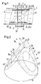
- FIG. 1 shows sections of a longitudinal section through a pipeline 1 the location of a flange transition 10 at which a ring 20 between Flanges 11 and 12 is inserted.
- Structure 25 In the interior of the ring 20 is one Structure 25 arranged for which only their location 25 'in the drawing is drawn in and in FIG. 2 in a schematic form 25 "as a Surface pattern is shown.
- Structure 25 acts as a static mixer a fluid 9 indicated by arrows 90 which connects the pipeline 1 flows through.
- the structure 25 can be made of sheet metal, for example Stamping and folding. That from the ring 20 and the Mixing structure 25 composite mixing element 2 is on Flange transition 10 mountable; it is by means of screws, not shown the flanges 11 and 12 attached.
- the structure 25 is each with a wing 25a or 25b on two inclined planes 21 and 22, the intersect on an intersection axis 23.
- the crossing axis 23 is arranged downstream of the ring 20.
- the wings 25a and 25b can be designed so that parts of them over the Intersection axis 23 on the side of the other wing 25b or 25a protrude (see Fig. 12).
- the mix-effective structure 25 can, if configured appropriately, be clamped between the flanges 11 and 12.
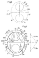
- FIG. 2 Form closed partial areas and open area pieces of structure 25 a surface pattern 5, which in a specific embodiment with closed partial areas 52, 51 ', 55, 56 and open area pieces 51, 520, 521, 522 in Fig. 4, wherein the surface pattern 5 in the Image plane is unfolded.
- Figures 2 and 3 is a surface pattern shown that as a reference system 4 for a characterization of Surface pattern 5 is introduced.
- the reference system 4 in Fig. 3 is the plane Unfolding the surface pattern 25 "shown as an oblique image in FIG. 2.
- the two wings 25a and 25b are largely complementary antisymmetric form in the following sense: 1.) It is a reference system 4 definable by the boundary lines 40, 40 ', 40 ", 43 of reference surfaces 41, 41', 42, 42 'and that with respect to the crossing axis 23 or Axis of symmetry 43 is mirror-symmetrical; 2.) the partial surfaces 52, 51 ', 55, 56 and patches 51, 520, 521, 522 of the patch 5 and the Reference surfaces 41, 41 ', 42, 42' of the reference system 4 cover common Areas 52, 51 ', 51, 520, 521, 522 that are smaller than the covering ones Surfaces 41, 41 ', 42, 42' or the same size.
- the closed and open partial surfaces form a with respect to the crossing axis 23 antisymmetric arrangement, for which the following applies: Crossing axis 23 or the axis of symmetry 53 the closed Partial surfaces 52, 51 'to lie on open partial surfaces 51, 520, 521, 522 come and that the reverse also applies. Because of this antisymmetry is a mapping between open and closed areas of the two Given wings.
- the three open ones arranged on the wing 25b Partial surfaces 520, 521, 522 taken together are practically congruent (same shape and area) to the associated closed partial area 52 of the other wing 25a.
- the open partial surface 51 of the wing 25a is congruent to the closed partial surface 51 'of the other wing 25b.
- FIG. 2 The special anti-symmetry of the mix-effective structure 25 now has Effect desired according to the invention, which is explained with reference to FIG. 2: Arrows 9a and 9b schematically show the flow pattern of the mixing fluid specified. In reality there are also eddies for a good mixing effect is essential. These eddies are with the present schematic illustration ignored because another aspect of Mixing effect should be explained.
- the arrows 9a are in the Main flow direction (arrow 90 in Fig. 1) oriented. Give the arrows 9b Partial flows of the fluid through the closed partial areas of the Structure 25 are distracted. Thanks to the complementary antisymmetry, they are Arrows 9b each directed against an arrow 9a. Express these relationships differs in that there is fluid exchange between the areas of the two Wing 25a and 25b takes place, so that a thorough mixing over the whole cross section of the pipeline 1 results.
- the mixing element 2 can be more general Mark as follows:
- the surface pattern 5 of the mix-effective Structure 25 is asymmetrical with respect to the crossing axis 23.
- the asymmetrical shape means that the pipe 1 flows through Fluid 9 can be deflected in such a way that partial flows 9b, which through partial surfaces of the one Wing 25a to the side of the other wing 25b are deflected there encounter largely non-redirected partial streams 9a. this is also valid vice versa with respect to deflected partial flows 9b of the other wing 25b.
- the structure 25 arranged in the interior of the pipeline 1 is included two ring pieces 6 and 6 'connected between the ring 20 and the Flange 11 - see Fig. 1 - be inserted.
- the structure 25 is on the Axis of symmetry 53 folded so that the right dash in Fig. 4 drawn angle arises.
- Also between the ring pieces 6, 6 'and both wings 25a, 25b is folded in such a way that the ring pieces 6, 6 'come to lie in the same plane. After folding, they form Ring pieces 6 and 6 'at their ends 61 and 62 or 61' and 62 'joints.
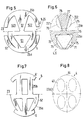
- FIGS. 5 to 8 Two further exemplary embodiments of the invention are shown in FIGS. 5 to 8 shown. While in one example the number of open patches on one wing 25a is one and on the other wing 25b is two in the other example, this number two or three. In these examples the surface pattern 5 differ relatively strongly from the pattern of Frame of reference 4.
- the surface pattern 5 according to FIG. 5 (with corresponding surfaces 51, 52, 521, 522 and 51 'as in the first example, Fig. 4) can do the same Reference system as in the first example Fig. 3 are assigned.
- Fig. 6 shows an overlay of the surface pattern 5 and the reference system 4. Common areas of this overlay that are up to 30% smaller than the covering surface pieces 51, 521, 522 or partial surfaces 51 ', 52 of the Are surface pattern 5, the closed partial surface 72 and the open partial surface 71 on the wing 25a and the closed Partial surfaces 71 'and the open partial surfaces 721, 722 on the wing 25a.
- FIG. 7 The other mix-effective structure 5 with the somewhat more complicated one Surface pattern 5 is shown in FIG. 7.
- a correspondingly more complex reference system 4 namely that of Fig. 8 be taken as a basis.
- the mixing element 2 according to the invention is intended to lead to a mixing result, which is associated with the smallest possible pressure loss. Therefore, the open areas of the wings 25a and 25b overall are not essential be smaller than the free cross section of the pipeline 1. This condition is fulfilled if the above-mentioned open areas are at least in total have the same area as the closed partial areas and if the inclination of levels 21 and 22 is relatively large, so that of angle included at the intersection axis 23 of 120 ° or less is.
- the flange mixer 2 can with a suitable training in the Pipe 1 can be installed and removed without disassembly part of the pipeline 1 is required. This requires that the Wings 25a and 25b largely in the area between the two End cross sections 13, 14 of the ring 20 (see Fig. 1) are arranged.
- the mixing element 2 is well suited for adding an additive to feed the flange point 10 into the pipeline 1.
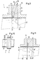
- Fig. 9 are Feed points for an additive 95 are shown, which are integrated in the ring 20 are. They are uniform by a plurality or a plurality arranged and equally large outlet openings 31 are formed.
- the Additive 95 is conveyed via a feed pipe 30 into an annular groove 3 'from which it through the outlet openings 31 into the effective range dash-dotted lines 25 'indicated mixer structure 25 arrives.
- feed pipes 30 for several additives or other fluids to be mixed may be provided.
- the many Outlet openings 31 can also enter an annular gap or radially inwards leading grooves in the ring pieces 6 and 6 ', the ring 20 or one inserted seal (not shown) are milled.
- Feed points 30 'for fluid to be mixed can also be upstream the mixing element can be arranged as illustrated in FIG. 10. about a nozzle 31 'feeds a fluid upstream of the mixing element 2.
- the aperture 8 can also be part of the mix-effective structure 25 his; the structure 25 may be formed on the periphery so that it is as Ring aperture works.
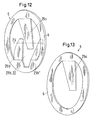
- FIG. 12 shows a further mix-effective structure 25.
- This consists of a closed ring 6, which between the pipe flanges 11, 12 (Fig. 1) can be inserted, a first wing 25a, which consists of a middle Web is formed, and a second wing 25b, which consists of two lateral Webs 25b 'and 25b "is composed.
- the wings 25a and 25b are like this formed parts of them over the crossing axis 23 to the side of the other wing 25b or 25a protrude.
- the middle bridge or the Both side webs can be missing, so that the mixed structure 25 has only one wing 25a.
- a mixing element 2, one such reduced structure 25, is also an inventive Mixing element.
- An example of such a structure 25, which has only one wing is shown in Fig. 13; it is missing compared to the embodiment of FIG Fig. 12 of the wing with the lateral webs 25b 'and 25b ".
- the mix-effective structure 25 can be made of flexible material, for example be made of thin spring sheet or plastic. At different throughput, the webs bend differently; the Flow resistance grows less with increasing throughput quickly, as if the bars were rigid.
- the mixing elements described above can be modified so that Parts of one or both wings 25a, 25b of the mixing structure 25 plane 21, 22 associated with the wing are bent out. So can in the example of FIG. 12, the two lateral webs 25b 'and 25b "around different angles can be bent out of the plane 22.
Landscapes
- Chemical & Material Sciences (AREA)
- Chemical Kinetics & Catalysis (AREA)
- Dispersion Chemistry (AREA)
- Forging (AREA)
- Pipe Accessories (AREA)
- Compositions Of Oxide Ceramics (AREA)
Abstract
Description
Die Erfindung betrifft ein Mischelement für einen Flanschübergang in einer
Rohrleitung gemäss Oberbegriff von Anspruch 1 und eine Rohrleitung mit
einem solchen Mischelement.The invention relates to a mixing element for a flange transition in one
Pipe according to the preamble of
Es sind statische Mischer bekannt, die in einem Rohrstück einer Rohrleitung angeordnet sind. Für den Einbau eines solchen Rohrstücks in die Rohrleitung müssen in der Regel zwei Flanschpaare vorhanden sein, zwei Flansche am Rohrstück und zwei zugeordnete Flansche an der Rohrleitung. Solche statische Mischer verursachen kleine Druckverluste, wenn sie - was in der Regel der Fall ist - den Querschnitt des Rohrstücks nicht stark verengen und damit nur in geringem Mass eine Wirbelablösung verursachen, die eine hohe Dissipation der Strömungsenergie zur Folge hat.Static mixers are known which are located in a pipe section of a pipeline are arranged. For the installation of such a pipe section in the pipeline As a rule, there must be two pairs of flanges, two flanges on Pipe section and two assigned flanges on the pipeline. Such static mixers cause small pressure drops when - what in the The rule is the case - do not narrow the cross-section of the pipe section significantly thus cause only a small degree of vertebral detachment, which is high Dissipation of the flow energy results.
Aus der US-A 5 839 828 ist ein Flanschmischer bekannt, für dessen Einbau lediglich ein Flanschpaar benötigt wird. Dieser Flanschmischer ist blendenartig ausgebildet. Seine mischwirksame Struktur umfasst zwei spiegelsymmetrische Flächenbereiche, zwischen denen sich eine Durchströmöffnung befindet; diese weist einen zentralen Engpass und zwei quer zum Engpass ausgedehnte, linsenförmige Zonen auf. Die Flächenbereiche können auf zwei Ebenen liegen, die gegeneinander geneigt sind und deren Kreuzungslinie - senkrecht auf einen Rohrquerschnitt projiziert - eine Mittelline des Engpasses bildet. In einem den zentralen Engpass durchstömenden Fluid entstehen aufgrund der Blendenwirkung des Engpasses Wirbel, die einerseits eine Mischwirkung auf zudosierte Additive haben und andererseits einen relativ grossen Druckabfall bewirken. Aufgrund der Spiegelsymmetrie erfolgt ein geringer Stoffaustausch zwischen den durch die Kreuzungslinie und Mittelline gegebenen Rohrhälften.From US-A 5 839 828 a flange mixer is known for its installation only one pair of flanges is required. This flange mixer is trained like an aperture. Its mix-effective structure comprises two mirror-symmetrical surface areas, between which there is a Flow opening is located; this has a central bottleneck and two Lenticular zones across the bottleneck. The Surface areas can lie on two levels that are inclined towards each other and their crossing line - projected vertically onto a pipe cross-section - forms a midline of the bottleneck. In a central bottleneck flowing fluid arise due to the aperture effect of the Bottleneck vortex, on the one hand a mixing effect on added additives have and on the other hand cause a relatively large pressure drop. Because of Due to the mirror symmetry, there is a low mass exchange between the the intersection line and midline given tube halves.
Flanschmischer haben gegenüber den in Rohrstücken angeordneten statischen Mischern den Vorteil, dass sie ein kleines Volumen haben. Nach gewissen Berechnungsvorschriften gelten sie dank des kleinen Volumens nicht als Druckbehälter und benötigen daher für eine Zulassung kein aufwendiges Prüfungsverfahren. Ein Nachteil ist, dass der Flanschmischer nur aus einem Mischelement besteht und dass er somit eine beschränkte Mischwirkung hat.Flange mixers have compared to those arranged in pipe sections static mixers have the advantage that they have a small volume. To They apply to certain calculation rules thanks to their small volume not as a pressure vessel and therefore do not require any for approval elaborate examination procedure. A disadvantage is that the flange mixer consists of only one mixing element and that it is therefore a limited one Has a mixing effect.
Aufgabe der Erfindung ist es, eine Alternative zu dem bekannten
Flanschmischer zu schaffen, der eine verbesserte Mischwirkung bei
niedrigem Druckverlust hat. Diese Aufgabe wird durch das im Anspruch 1
definierte Mischelement, das ein Flanschmischer ist, gelöst. Beim Zumischen
eines Additivs mit dem erfindungsgemässen Mischelement kann das Additiv
über eine Vielzahl von Zutrittstellen eingespeist werden, so dass die
Mischwirkung des Flanschmischers, der nur aus einem Mischelement
besteht, ausreichen kann.The object of the invention is to provide an alternative to the known
Flange mixer to create an improved mixing effect
has low pressure drop. This object is achieved by the in
Das Mischelement ist für einen Flanschübergang in einer Rohrleitung vorgesehen und ist zwischen zwei Flanschen der Rohrleitung montierbar. Es umfasst eine mischwirksame Struktur, die durch einen oder zwei Flügel innerhalb eines Ringes gebildet ist. Zwei zueinander geneigte Ebenen sind definierbar, wobei auf der einen Ebene der eine Flügel oder auf beiden Ebenen die zwei Flügel angeordnet sind. Die beiden Ebenen schneiden sich auf einer Kreuzungsachse. Geschlossene Teilflächen sowie offene Flächenstücke der Flügel bilden ein Flächenmuster, das bezüglich der Kreuzungsachse asymmetrisch ausgebildet ist. Durch die asymmetrische Form ist ein die Rohrleitung durchströmendes Fluid derart umlenkbar, dass Teilströme aus einer Rohrhälfte durch Teilflächen der einen Ebene in die andere Rohrhälfte umgelenkt werden und dort auf weitgehend nicht umgelenkte Teilströme stossen, wobei dies auch umgekehrt bezüglich der anderen Ebene gilt, falls auf dieser ein zweiter, Strukturelemente aufweisender Flügel existiert.The mixing element is for a flange transition in a pipe provided and can be installed between two flanges of the pipeline. It includes a mix structure by one or two wings is formed within a ring. There are two inclined planes definable, whereby on one level one wing or on both Levels arranged in two wings. The two levels intersect on an intersection axis. Closed partial areas as well as open ones Surfaces of the wings form a surface pattern that is related to the Crossing axis is asymmetrical. Because of the asymmetrical Form, a fluid flowing through the pipeline can be deflected such that Partial flows from a pipe half through partial surfaces of one level into the other pipe half are redirected and there largely not diverted partial flows encounter, this also vice versa with respect to another level applies if there is a second, structural elements showing wing exists.
Die abhängigen Ansprüche 2 bis 9 betreffen vorteilhafte Ausführungsformen
des erfindungsgemässen Mischelements. Eine Rohrleitung mit einem
derartigen Mischelement ist Gegenstand des Anspruchs 10.The dependent claims 2 to 9 relate to advantageous embodiments
of the mixing element according to the invention. A pipe with one
Such a mixing element is the subject of
Nachfolgend wird die Erfindung anhand der Zeichnungen erläutert. Es zeigen:
- Fig. 1
- ausschnittsweise einen Längsschnitt durch eine Rohrleitung bei einer Flanschstelle mit eingelegtem Ring,
- Fig. 2
- eine schematische Darstellung zum Strömungsverlauf bei einem erfindungsgemässen Mischelement,
- Fig. 3
- ein Bezugssystem für eine Definition der mischwirksamen Struktur des erfindungsgemässen Mischelements,
- Fig. 4
- ein Flächenmuster zu dem Mischelement der Fig. 3 gemäss einem ersten Ausführungsbeispiel,
- Fig. 5
- ein Flächenmuster zu einem zweiten Ausführungsbeispiel,
- Fig. 6
- eine Hilfsdarstellung für die Definition der mischwirksamen Struktur,
- Fig. 7
- ein Flächenmuster zu einem dritten Ausführungsbeispiel,
- Fig. 8
- ein Bezugssystem, das dem Flächenmuster der Fig. 7 zugeordnet werden kann,
- Fig. 9
- ausschnittsweise einen Längsschnitt durch einen Rand eines Mischelements mit Einspeisestellen für ein Additiv,
- Fig. 10
- eine Seitenansicht auf eine Rohrleitung mit einer stromaufwärts vor dem Mischelement angeordneten Einspeisestelle für ein Additiv,
- Fig. 11
- ausschnittsweise einen Längsschnitt durch einen Rand eines Mischelements mit einer zusätzlichen Blende,
- Fig. 12
- eine weitere mischwirksame Struktur und
- Fig. 13
- eine Modifikation der Struktur aus Fig. 12 mit nur einem Flügel, die auch Teil eines erfindungsgemässen Mischelements ist.
- Fig. 1
- sections of a longitudinal section through a pipe at a flange point with an inserted ring,
- Fig. 2
- 2 shows a schematic illustration of the flow pattern in a mixing element according to the invention,
- Fig. 3
- a reference system for a definition of the mix-effective structure of the mixing element according to the invention,
- Fig. 4
- 3 according to a first exemplary embodiment,
- Fig. 5
- a surface pattern to a second embodiment,
- Fig. 6
- an auxiliary representation for the definition of the mix-effective structure,
- Fig. 7
- a surface pattern to a third embodiment,
- Fig. 8
- a reference system that can be assigned to the surface pattern of FIG. 7,
- Fig. 9
- sections of a longitudinal section through an edge of a mixing element with feed points for an additive,
- Fig. 10
- 2 shows a side view of a pipeline with an infeed point for an additive arranged upstream of the mixing element,
- Fig. 11
- sections of a longitudinal section through an edge of a mixing element with an additional screen,
- Fig. 12
- another mix effective structure and
- Fig. 13
- a modification of the structure of FIG. 12 with only one wing, which is also part of a mixing element according to the invention.
Fig. 1 zeigt ausschnittsweise einen Längsschnitt durch eine Rohrleitung 1 an
der Stelle eines Flanschübergangs 10, an dem ein Ring 20 zwischen
Flanschen 11 und 12 eingelegt ist. Im Innenbereich des Rings 20 ist eine
Struktur 25 angeordnet, für die in der Zeichnung nur deren Ort 25'
eingezeichnet ist und die in Fig. 2 in einer schematischen Form 25" als ein
Flächenmuster dargestellt ist. Die Struktur 25 wirkt als statischer Mischer auf
ein mit Pfeilen 90 angedeutetes Fluid 9 ein, das die Rohrleitung 1
durchströmt. Die Struktur 25 lässt sich beispielsweise aus einem Blech, durch
Stanzen und Abkanten, herstellen. Das aus dem Ring 20 und der
mischwirksamen Struktur 25 zusammengesetzte Mischelement 2 ist am
Flanschübergang 10 montierbar; es ist mittels nicht dargestellter Schrauben
der Flansche 11 und 12 befestigt. Die Struktur 25 ist mit je einem Flügel 25a
bzw. 25b auf zwei zueinander geneigten Ebenen 21 und 22 angeordnet, die
sich auf einer Kreuzungsachse 23 schneiden. Die Kreuzungsachse 23 ist
bezüglich dem Ring 20 stromabwärts angeordnet. Bei einer umgekehrten
Anordnung des Mischelements 2 ergibt sich auch eine Mischwirkung, die aber
bezüglich Druckabfall und Mischqualität weniger gut ist. Die Flügel 25a und
25b können so ausgebildet sein, dass Teile von ihnen über die
Kreuzungsachse 23 auf die Seite des anderen Flügels 25b bzw. 25a
hinausragen (vgl. Fig. 12).1 shows sections of a longitudinal section through a
Die Verwendung eines separaten Rings 20 ist vorteilhaft aber nicht
notwendig. Die mischwirksame Struktur 25 kann, falls geeignet ausgebildet,
zwischen die Flansche 11 und 12 eingeklemmt werden.However, the use of a
Geschlossene Teilflächen und offene Flächenstücke der Struktur 25 bilden
ein Flächenmuster 5, das in einer konkreten Ausgestaltung mit
geschlossenen Teilflächen 52, 51', 55, 56 und offenen Flächenstücken 51,
520, 521, 522 in Fig. 4 gezeigt ist, wobei das Flächenmuster 5 in die
Bildebene ausgefaltet ist. In den Figuren 2 und 3 ist ein Flächenmuster
dargestellt, das als Bezugssystem 4 für eine Charakterisierung des
Flächenmusters 5 eingeführt wird. Das Bezugssystem 4 in Fig. 3 ist die ebene
Ausfaltung des in Fig. 2 als Schrägbild gezeigten Flächenmusters 25".Form closed partial areas and open area pieces of
Die beiden Flügel 25a und 25b weisen weitgehend eine komplementär
antisymmetrische Form in folgendem Sinn auf: 1.) Es ist ein Bezugssystems 4
definierbar, das durch Grenzlinien 40, 40', 40", 43 von Bezugsflächen 41, 41',
42, 42' gebildet ist und das bezüglich der Kreuzungsachse 23 oder
Symmetrieachse 43 spiegelsymmetrisch ist; 2.) die Teilflächen 52, 51', 55, 56
und Flächenstücke 51, 520, 521, 522 des Flächenmusters 5 und die
Bezugsflächen 41, 41', 42, 42' des Bezugssystem 4 decken gemeinsame
Bereiche 52, 51', 51, 520, 521, 522 ab, die kleiner als die abdeckenden
Flächen 41, 41', 42, 42' oder gleich gross sind. Diese Bereiche sind dem
Flächenmuster 5 entsprechend geschlossene Partialflächen 52, 51' oder
offene Partialflächen 51, 520, 521, 522; und 3.) die geschlossenen und
offenen Partialflächen bilden bezüglich der Kreuzungsachse 23 eine
antisymmetrische Anordnung, für die gilt, dass bei einer Spiegelung an der
Kreuzungsachse 23 oder der Symmetrieachse 53 die geschlossenen
Partialflächen 52, 51' auf offene Partialflächen 51, 520, 521, 522 zu liegen
kommen und dass das Umgekehrte ebenso gilt. Durch diese Antisymmetrie
ist eine Zuordnung zwischen offenen und geschlossenen Flächen der beiden
Flügel gegeben. Die auf dem Flügel 25b angeordneten drei offenen
Partialflächen 520, 521, 522 sind zusammengenommen praktisch kongruent
(gleiche Form und Fläche) zur zugeordneten geschlossenen Partialfläche 52
des anderen Flügels 25a. Die offene Partialfäche 51 des Flügels 25a ist
kongruent zur geschlossenen Partialfläche 51' des anderen Flügels 25b.The two
Die besondere Antisymmetrie der mischwirksamen Struktur 25 hat nun die
erfindungsgemäss angestrebte Wirkung, die anhand der Fig. 2 erläutert wird:
Mit den Pfeilen 9a und 9b ist schematisch der Strömungsverlauf des zu
mischenden Fluids angegeben. In Wirklichkeit treten auch Wirbel auf, die für
einen guten Mischeffekt wesentlich sind. Diese Wirbel sind bei der
vorliegenden schematischen Darstellung ignoriert, da ein anderer Aspekt der
Mischwirkung erläutert werden soll. Die Pfeile 9a sind in der
Hauptströmungsrichtung (Pfeil 90 in Fig. 1) orientiert. Die Pfeile 9b geben
Teilströme des Fluids an, die durch die geschlossenen Teilflächen der
Struktur 25 abgelenkt sind. Dank der komplementären Antisymmetrie sind die
Pfeile 9b jeweils gegen einen Pfeil 9a gerichtet. Diese Verhältnisse äussern
sich dadurch, dass ein Fluidaustausch zwischen den Bereichen der beiden
Flügel 25a und 25b stattfindet, so dass sich eine Durchmischung über den
ganzen Querschnitt der Rohrleitung 1 ergibt.The special anti-symmetry of the mix-
Das erfindungsgemässe Mischelement 2 lässt sich allgemeiner
folgendermassen kennzeichnen: Das Flächenmuster 5 der mischwirksamen
Struktur 25 ist bezüglich der Kreuzungsachse 23 asymmetrisch ausgebildet.
Durch die asymmetrische Form ist ein die Rohrleitung 1 durchströmendes
Fluid 9 derart umlenkbar, dass Teilströme 9b, die durch Teilflächen des einen
Flügels 25a auf die Seite des anderen Flügels 25b umgelenkt werden, dort
auf weitgehend nicht umgelenkte Teilströme 9a stossen. Dies gilt auch
umgekehrt bezüglich umgelenkten Teilströmen 9b des anderen Flügels 25b.The mixing
Zu der in Fig. 4 dargestellten Struktur 25 sind noch folgende Bemerkungen zu
machen: Die im Innenraum der Rohrleitung 1 angeordnete Struktur 25 ist mit
zwei Ringstücken 6 und 6' verbunden, die zwischen den Ring 20 und den
Flansch 11 - siehe Fig. 1 - eingelegt werden. Die Struktur 25 wird an der
Symmetrieachse 53 abgekantet, so dass der rechts in Fig. 4 strichpunktiert
gezeichnete Winkel entsteht. Auch zwischen den Ringstücken 6, 6' und den
beiden Flügeln 25a, 25b wird abgekantet und zwar so, dass die Ringstücke 6,
6' in die gleiche Ebene zu liegen kommen. Nach dem Abkanten bilden die
Ringstücke 6 und 6' an ihren Enden 61 und 62 bzw. 61' und 62' Stossstellen.The following comments should also be made regarding the
Zwei weitere Ausführungsbeispiele der Erfindung sind in den Figuren 5 bis 8
dargestellt. Während im einen Beispiel die Anzahl offener Flächenstücke auf
dem einen Flügel 25a eins und auf dem anderen Flügel 25b zwei beträgt, ist
beim anderen Beispiel diese Anzahl zwei bzw. drei. Bei diesen Beispielen
unterscheiden sich die Flächenmuster 5 relativ stark von dem Muster des
Bezugssystems 4.Two further exemplary embodiments of the invention are shown in FIGS. 5 to 8
shown. While in one example the number of open patches on
one
Dem Flächenmuster 5 gemäss Fig. 5 (mit entsprechenden Flächen 51, 52,
521, 522 und 51' wie im ersten Beispiel, Fig. 4) kann das gleiche
Bezugssystem wie im ersten Beispiel Fig. 3 zugeordnet werden. Fig. 6 zeigt
eine Überlagerung des Flächenmusters 5 und des Bezugssystems 4.
Gemeinsame Bereiche dieser Überlagerung, die um maximal 30% kleiner als
die abdeckenden Flächenstücke 51, 521, 522 bzw. Teilflächen 51', 52 des
Flächenmusters 5 sind, sind die geschlossene Partialfläche 72 sowie die
offene Partialfläche 71 auf dem Flügel 25a und die geschlossene
Partialflächen 71' sowie die offenen Partialflächen 721, 722 auf dem Flügel
25a. Bezüglich diesen Partialflächen besteht eine komplementäre
Antisymmetrie im Einklang mit der Definition des Flächenmusters 5, das die
Struktur 25 erfindungsgemäss aufweist. Bei dieser Definition werden die in
Fig. 6 weiss gelassenen, kleinen Teilflächen 75 vernachlässigt.The
Die andere mischwirksame Struktur 5 mit dem etwas komplizierteren
Flächenmuster 5 ist in Fig. 7 abgebildet. Bei diesem Ausführungsbeispiel
muss ein entsprechend komplizierteres Bezugssystem 4, nämlich jenes der
Fig. 8, zugrunde gelegt werden. Eine Überlagerung des Musters 5 der Fig. 7
mit dem Bezugssystem der Fig. 8 führt - analog zur Überlagerung in Fig. 6 -
zu gemeinsamen Bereichen, für die wieder eine komplementäre
Antisymmetrie besteht. Auf eine explizite Durchführung dieser Überlagerung
wird verzichtet.The other mix-
Das erfindungsgemässe Mischelement 2 soll zu einem Mischergebnis führen,
das mit einem möglichst kleinen Druckverlust verbunden ist. Daher sollen die
offenen Flächenstücke der Flügel 25a und 25b gesamthaft nicht wesentlich
kleiner als der freie Querschnitt der Rohrleitung 1 sein. Diese Bedingung ist
erfüllt, wenn die genannten offenen Flächenstücke gesamthaft mindestens
den gleichen Flächeninhalt wie die geschlossenen Teilflächen aufweisen und
wenn die Neigung der Ebenen 21 und 22 relativ gross ist, so dass der von
ihnen an der Kreuzungsachse 23 eingeschlossene Winkel 120° oder kleiner
ist.The mixing
Der Flanschmischer 2 kann bei einer geeigneten Ausbildung in die
Rohrleitung 1 ein- und ausgebaut werden, ohne dass dabei eine Demontage
eines Teils der Rohrleitung 1 erforderlich ist. Dazu ist erforderlich, dass die
Flügel 25a und 25b weitgehend im Bereich zwischen den beiden
Endquerschnitten 13, 14 des Rings 20 (siehe Fig. 1) angeordnet sind. The
Für das Flächenmuster 5 der mischwirksamen Struktur 25 kann eine
Spiegelsymmetrie bezüglich einer Achse 44 (siehe Fig. 3 oder 8), die
senkrecht zur Kreuzungsachse 23 steht, vorgesehen werden.One can be used for the
Das erfindungsgemässe Mischelement 2 eignet sich gut dazu, ein Additiv an
der Flanschstelle 10 in die Rohrleitung 1 einzuspeisen. In Fig. 9 sind
Einspeisestellen für ein Additiv 95 dargestellt, die in den Ring 20 integriert
sind. Sie werden durch eine Mehrzahl oder Vielzahl von gleichmässig
angeordneten sowie gleich grossen Austrittsöffnungen 31 gebildet. Das
Additiv 95 wird über ein Zuleitungsrohr 30 in eine Ringnut 3' gefördert, aus der
es über die Austrittsöffnungen 31 in den Wirkbereich der durch
strichpunktierte Linien 25' angedeuteten Mischerstruktur 25 gelangt.
Selbstverständlich können auch Zuleitungsrohre 30 für mehrere Additive oder
sonstige beizumischende Fluide vorgesehen sein. An die Stelle der vielen
Austrittsöffnungen 31 kann auch ein Ringspalt treten oder radial nach innen
führende Nuten, die in die Ringstücke 6 und 6', den Ring 20 oder eine
eingelegte Dichtung (nicht dargestellt) eingefräst sind.The mixing
Einspeisestellen 30' für beizumischende Fluid können auch stromaufwärts vor
dem Mischelement angeordnet werden, wie es in Fig. 10 illustriert ist. Über
eine Düse 31' wird ein Fluid vor dem Mischelement 2 eingespeist.Feed points 30 'for fluid to be mixed can also be upstream
the mixing element can be arranged as illustrated in FIG. 10. about
a nozzle 31 'feeds a fluid upstream of the mixing
Um den Fluidstrom der Rohrleitung 1 im Bereich des Flanschmischers 2
stärker zu verwirbeln, können - siehe Fig. 11 - mit einer Blende 8, die
zusammen mit der Mischerstruktur 25 an der Flanschstelle 10 eingelegt wird,
in der Strömung 91 zusätzliche Wirbel 92 hinter der Blendenöffnung 80
erzeugt werden. Die Blende 8 kann auch Teil der mischwirksamen Struktur 25
sein; die Struktur 25 kann an der Peripherie so ausgebildet sein, dass sie als
Ringblende wirkt.Around the fluid flow of the
Fig. 12 zeigt eine weitere mischwirksame Struktur 25. Diese besteht aus
einem geschlossenen Ring 6, der zwischen die Rohrflansche 11, 12 (Fig. 1)
eingelegt werden kann, einem ersten Flügel 25a, der aus einem mittleren
Steg gebildet ist, und einem zweiten Flügel 25b, der sich aus zwei seitlichen
Stegen 25b' und 25b" zusammensetzt. Die Flügel 25a und 25b sind so
ausgebildet, dass Teile von ihnen über die Kreuzungsachse 23 auf die Seite
des anderen Flügels 25b bzw. 25a hinausragen. Der mittlere Steg oder die
beiden seitlichen Stege können fehlen, so dass die mischwirksame Struktur
25 nur einen Flügel 25a aufweist. Ein Mischelement 2, das eine derart
reduzierte Struktur 25 aufweist, ist ebenfalls ein erfindungsgemässes
Mischelement. Ein Beispiel für eine solche Struktur 25, die nur einen Flügel
hat, ist in Fig. 13 dargestellt; es fehlt verglichen mit der Ausführungsform der
Fig. 12 der Flügel mit den seitlichen Stegen 25b' und 25b".12 shows a further mix-
Die mischwirksame Struktur 25 kann aus flexiblem Material, beispielsweise
aus dünnem Federblech oder Kunststoff hergestellt sein. Bei
unterschiedlichem Durchsatz biegen so die Stege unterschiedlich aus; der
Strömungswiderstand wächst somit bei zunehmendem Durchsatz weniger
schnell, als wenn die Stege starr wären.The mix-
Die oben beschriebenen Mischelemente können so modifiziert werden, dass
Teile eines oder beider Flügel 25a, 25b der mischwirksamen Struktur 25 aus
der dem Flügel zugeordneten Ebene 21, 22 hinausgebogen sind. So können
beim Beispiel der Fig. 12 die zwei seitlichen Stegen 25b' und 25b" um
verschiedene Winkel aus der Ebene 22 hinausgebogen sein.The mixing elements described above can be modified so that
Parts of one or both
Claims (10)
dadurch gekennzeichnet, dass das Flächenmuster bezüglich der Kreuzungsachse asymmetrisch ausgebildet ist und dass durch die asymmetrische Form ein die Rohrleitung durchströmendes Fluid (9) derart umlenkbar ist, dass Teilströme (9b) aus einer Rohrhälfte durch Teilflächen der einen Ebene (21) in die andere Rohrhälfte umgelenkt werden und dort auf weitgehend nicht umgelenkte Teilströme stossen, wobei dies auch umgekehrt bezüglich der anderen Ebene (22) gilt, falls auf dieser ein zweiter, Strukturelemente aufweisender Flügel (25b) existiert.Mixing element (2) for a flange transition (10) in a pipeline (1) which can be mounted between two flanges (11, 12) of the pipeline and which comprises a mix-effective structure (25) which is formed by one or two wings (25a, 25b ) is formed within a ring (20), two mutually inclined planes (21, 22) being definable, on one plane of which the one wing or on which planes the two wings are arranged, the two planes on an intersection axis (23) cut and form closed partial surfaces (52, 51 ') and open surface pieces (51, 520, 521, 522) of the wings to form a surface pattern (5),
characterized in that the surface pattern is asymmetrical with respect to the crossing axis and that the asymmetrical shape allows a fluid (9) flowing through the pipeline to be deflected such that partial flows (9b) from one pipe half through partial surfaces of one plane (21) into the other pipe half are deflected and encounter largely non-deflected partial flows there, this also applies vice versa with respect to the other plane (22) if there is a second wing (25b) having structural elements on it.
3. diese geschlossenen und offenen Partialflächen bilden bezüglich der Kreuzungsachse eine angenähert antisymmetrische Anordnung, für die gilt, dass bei einer Spiegelung die geschlossenen Partialflächen (72; 71') weitgehend auf offene Partialflächen (721, 722; 71) zu liegen kommen und dass das Umgekehrte ebenso gilt.Mixing element according to claim 1, characterized in that two wings (25a, 25b) form the mix-effective structure (25), the entirety of the closed partial areas (52, 51 ') lie on a coherent surface and the two wings approximately have a complementary antisymmetric shape have the following meaning: 1. a reference system (4) can be defined, which is formed by closed boundary lines (40, 40 ', 40 ") of reference surfaces (41, 42, 41', 42 ') and which is related to the crossing axis (23 ) is mirror-symmetrical; 2. the surface pieces (51, 521, 522) and partial surfaces (51 ', 52) of the wings and the reference surfaces of the reference system cover common areas (71, 72, 71', 721, 722), which by a maximum 30% smaller than the covering surface pieces (51, 521, 522) or partial surfaces (51 ', 52) of the surface pattern (5), these regions being closed or open partial surfaces corresponding to the surface pattern; and
3. These closed and open partial areas form an approximately antisymmetric arrangement with respect to the crossing axis, for which it applies that the closed partial areas (72; 71 ') largely lie on open partial areas (721, 722; 71) during mirroring and that The reverse also applies.
Priority Applications (1)
| Application Number | Priority Date | Filing Date | Title |
|---|---|---|---|
| EP01810359A EP1153650B1 (en) | 2000-05-08 | 2001-04-10 | Mixing element for a flange junction in a pipe |
Applications Claiming Priority (3)
| Application Number | Priority Date | Filing Date | Title |
|---|---|---|---|
| EP00810390 | 2000-05-08 | ||
| EP00810390 | 2000-05-08 | ||
| EP01810359A EP1153650B1 (en) | 2000-05-08 | 2001-04-10 | Mixing element for a flange junction in a pipe |
Publications (2)
| Publication Number | Publication Date |
|---|---|
| EP1153650A1 true EP1153650A1 (en) | 2001-11-14 |
| EP1153650B1 EP1153650B1 (en) | 2005-07-20 |
Family
ID=8174681
Family Applications (1)
| Application Number | Title | Priority Date | Filing Date |
|---|---|---|---|
| EP01810359A Expired - Lifetime EP1153650B1 (en) | 2000-05-08 | 2001-04-10 | Mixing element for a flange junction in a pipe |
Country Status (10)
| Country | Link |
|---|---|
| US (1) | US6595682B2 (en) |
| EP (1) | EP1153650B1 (en) |
| JP (1) | JP4704600B2 (en) |
| AT (1) | ATE299751T1 (en) |
| BR (1) | BR0101798B1 (en) |
| CA (1) | CA2343561C (en) |
| DE (1) | DE50106757D1 (en) |
| ES (1) | ES2246304T3 (en) |
| MX (1) | MXPA01004119A (en) |
| SG (1) | SG118073A1 (en) |
Cited By (4)
| Publication number | Priority date | Publication date | Assignee | Title |
|---|---|---|---|---|
| EP1302236A1 (en) * | 2001-10-16 | 2003-04-16 | Sulzer Chemtech AG | Pipe segment with a feeding port for an additiv |
| US6811302B2 (en) | 2001-10-16 | 2004-11-02 | Sulzer Chemtech Ag | Pipe member having an infeed point for an additive |
| WO2014084276A1 (en) * | 2012-11-27 | 2014-06-05 | 辻 清 | Aeration nozzle, and blockage removal method for said aeration nozzle |
| TWI491435B (en) * | 2012-01-25 | 2015-07-11 | 亞斯通科技有限公司 | Gas mixing arrangement |
Families Citing this family (21)
| Publication number | Priority date | Publication date | Assignee | Title |
|---|---|---|---|---|
| DE10019759C2 (en) * | 2000-04-20 | 2003-04-30 | Tracto Technik | Static mixing system |
| ATE235311T1 (en) * | 2000-06-19 | 2003-04-15 | Balcke Duerr Energietech Gmbh | MIXER FOR MIXING AT LEAST TWO GAS STREAMS OR OTHER NEWTONIAN LIQUIDS |
| US7011180B2 (en) * | 2002-09-18 | 2006-03-14 | Savant Measurement Corporation | System for filtering ultrasonic noise within a fluid flow system |
| CA2460292C (en) * | 2003-05-08 | 2011-08-23 | Sulzer Chemtech Ag | A static mixer |
| US20070070807A1 (en) * | 2003-05-19 | 2007-03-29 | Maarten Bracht | Process to upgrade kerosenes and a gasoils from naphthenic and aromatic crude petroleum sources |
| AU2003292650A1 (en) * | 2003-12-26 | 2005-08-12 | Shinyou Technologies Inc. | Static mixer |
| JP4989062B2 (en) * | 2005-04-28 | 2012-08-01 | バブコック日立株式会社 | Fluid mixing device |
| DE602006006438D1 (en) | 2006-08-10 | 2009-06-04 | Robert W Glanville | Mixing system for piping with adjustable static mixer |
| US7845688B2 (en) | 2007-04-04 | 2010-12-07 | Savant Measurement Corporation | Multiple material piping component |
| TWI417135B (en) * | 2007-06-22 | 2013-12-01 | Sulzer Chemtech Ag | Static mixing element |
| EP2111916B1 (en) | 2008-04-21 | 2012-10-24 | Swenox AB | Gas treatment apparatus, vehicle equipped with it and method for treatment of an exhaust gas |
| DE102010027908A1 (en) * | 2010-04-19 | 2011-10-20 | Infracor Gmbh | tubular reactor |
| ITBO20110533A1 (en) * | 2011-09-16 | 2013-03-17 | Magneti Marelli Spa | DISCHARGE SYSTEM OF AN INTERNAL COMBUSTION ENGINE PROVIDED WITH AN ADDITIVE INJECTION DEVICE |
| EP3352889B1 (en) * | 2015-09-24 | 2019-09-04 | Tetra Laval Holdings & Finance S.A. | Baffle pipe segment, injector device and dissolving installation |
| WO2018107268A1 (en) * | 2016-12-12 | 2018-06-21 | Canada Pipeline Accessories, Co. Ltd. | Static mixer for fluid flow in a pipeline |
| GB2581919B (en) | 2018-05-07 | 2023-03-15 | Canada Pipeline Access Co Ltd | Pipe assembly with static mixer and flow conditioner |
| PT3852912T (en) | 2018-09-20 | 2022-11-25 | Noram Eng And Constructors Ltd | Fluid mixing device |
| US10737227B2 (en) | 2018-09-25 | 2020-08-11 | Westfall Manufacturing Company | Static mixer with curved fins |
| USD976384S1 (en) | 2020-01-13 | 2023-01-24 | Canada Pipeline Accessories Co., Ltd. | Static mixer for fluid flow |
| NO345609B1 (en) * | 2020-02-11 | 2021-05-10 | Stauper Offshore As | Static mixer including a mixing element |
| US11285448B1 (en) * | 2021-04-12 | 2022-03-29 | William J. Lund | Static mixer inserts and static mixers incorporating same |
Citations (7)
| Publication number | Priority date | Publication date | Assignee | Title |
|---|---|---|---|---|
| US1610507A (en) * | 1925-03-30 | 1926-12-14 | Peter H Foley | Auxiliary air inlet and mixing device |
| US3090603A (en) * | 1960-03-01 | 1963-05-21 | Babcock & Wilcox Co | Apparatus for mixing fluids |
| US4019719A (en) * | 1975-06-05 | 1977-04-26 | Schuster Hans H | Fluid mixing device |
| EP0063729A2 (en) * | 1981-04-25 | 1982-11-03 | Gerhart Prof. Dr. Eigenberger | Apparatus for the inversion and mixture of flowing materials |
| US4758098A (en) * | 1985-12-11 | 1988-07-19 | Sulzer Brothers Limited | Static mixing device for fluids containing or consisting of solid particles |
| US5522661A (en) * | 1994-02-16 | 1996-06-04 | Tokyo Nisshin Jabara Co., Ltd. | Static mixing module and mixing apparatus using the same |
| US5839828A (en) * | 1996-05-20 | 1998-11-24 | Glanville; Robert W. | Static mixer |
Family Cites Families (12)
| Publication number | Priority date | Publication date | Assignee | Title |
|---|---|---|---|---|
| US1199243A (en) * | 1916-03-01 | 1916-09-26 | Eli J Bushey | Mixer. |
| US1569519A (en) * | 1924-01-15 | 1926-01-12 | Elmer H Middaugh | Fuel mixer for internal-combustion engines |
| GB1563994A (en) * | 1975-05-15 | 1980-04-02 | Albright & Wilson | Sulph(on)ation process and mixer |
| DE2522106C3 (en) * | 1975-05-17 | 1982-04-15 | Bayer Ag, 5090 Leverkusen | Device for the continuous mixing of flowable substances and method for producing a mixing insert |
| US4313680A (en) * | 1979-11-05 | 1982-02-02 | Chevron Research Company | Reactor for fast reactions |
| US4929088A (en) * | 1988-07-27 | 1990-05-29 | Vortab Corporation | Static fluid flow mixing apparatus |
| JP2845259B2 (en) * | 1992-08-31 | 1999-01-13 | 東京日進ジャバラ株式会社 | Manufacturing method of static mixing parts |
| EP0655275B1 (en) * | 1993-11-26 | 1999-10-06 | Sulzer Chemtech AG | Static mixing device |
| US5967658A (en) * | 1998-07-28 | 1999-10-19 | Kam Controls Incorporated | Static mixing apparatus and method |
| US6109781A (en) * | 1999-02-16 | 2000-08-29 | Ogasawara; Toshiyuki | Element of a mixing apparatus |
| US6394644B1 (en) * | 1999-06-21 | 2002-05-28 | Koch-Glitsch, Inc. | Stacked static mixing elements |
| JP2001179065A (en) * | 1999-12-28 | 2001-07-03 | Satsuki Kogyo:Kk | Mixer |
-
2001
- 2001-04-09 CA CA002343561A patent/CA2343561C/en not_active Expired - Fee Related
- 2001-04-10 DE DE50106757T patent/DE50106757D1/en not_active Expired - Lifetime
- 2001-04-10 EP EP01810359A patent/EP1153650B1/en not_active Expired - Lifetime
- 2001-04-10 ES ES01810359T patent/ES2246304T3/en not_active Expired - Lifetime
- 2001-04-10 AT AT01810359T patent/ATE299751T1/en not_active IP Right Cessation
- 2001-04-17 SG SG200102359A patent/SG118073A1/en unknown
- 2001-04-25 MX MXPA01004119A patent/MXPA01004119A/en active IP Right Grant
- 2001-04-30 US US09/846,493 patent/US6595682B2/en not_active Expired - Lifetime
- 2001-05-07 JP JP2001135676A patent/JP4704600B2/en not_active Expired - Fee Related
- 2001-05-08 BR BRPI0101798-5A patent/BR0101798B1/en not_active IP Right Cessation
Patent Citations (7)
| Publication number | Priority date | Publication date | Assignee | Title |
|---|---|---|---|---|
| US1610507A (en) * | 1925-03-30 | 1926-12-14 | Peter H Foley | Auxiliary air inlet and mixing device |
| US3090603A (en) * | 1960-03-01 | 1963-05-21 | Babcock & Wilcox Co | Apparatus for mixing fluids |
| US4019719A (en) * | 1975-06-05 | 1977-04-26 | Schuster Hans H | Fluid mixing device |
| EP0063729A2 (en) * | 1981-04-25 | 1982-11-03 | Gerhart Prof. Dr. Eigenberger | Apparatus for the inversion and mixture of flowing materials |
| US4758098A (en) * | 1985-12-11 | 1988-07-19 | Sulzer Brothers Limited | Static mixing device for fluids containing or consisting of solid particles |
| US5522661A (en) * | 1994-02-16 | 1996-06-04 | Tokyo Nisshin Jabara Co., Ltd. | Static mixing module and mixing apparatus using the same |
| US5839828A (en) * | 1996-05-20 | 1998-11-24 | Glanville; Robert W. | Static mixer |
Cited By (8)
| Publication number | Priority date | Publication date | Assignee | Title |
|---|---|---|---|---|
| EP1302236A1 (en) * | 2001-10-16 | 2003-04-16 | Sulzer Chemtech AG | Pipe segment with a feeding port for an additiv |
| US6811302B2 (en) | 2001-10-16 | 2004-11-02 | Sulzer Chemtech Ag | Pipe member having an infeed point for an additive |
| CN1325150C (en) * | 2001-10-16 | 2007-07-11 | 苏舍化学技术有限公司 | Pipe fitting with additive material feeding device |
| TWI491435B (en) * | 2012-01-25 | 2015-07-11 | 亞斯通科技有限公司 | Gas mixing arrangement |
| US10232328B2 (en) | 2012-01-25 | 2019-03-19 | General Electric Technology Gmbh | Gas mixing arrangement |
| WO2014084276A1 (en) * | 2012-11-27 | 2014-06-05 | 辻 清 | Aeration nozzle, and blockage removal method for said aeration nozzle |
| CN104884393A (en) * | 2012-11-27 | 2015-09-02 | 株式会社清和 | Aeration nozzle, and blockage removal method for said aeration nozzle |
| CN104884393B (en) * | 2012-11-27 | 2016-10-12 | 株式会社清和 | A kind of aeration nozzle and the method removing the blocking of this aeration nozzle |
Also Published As
| Publication number | Publication date |
|---|---|
| JP4704600B2 (en) | 2011-06-15 |
| MXPA01004119A (en) | 2002-06-04 |
| SG118073A1 (en) | 2006-01-27 |
| ES2246304T3 (en) | 2006-02-16 |
| CA2343561A1 (en) | 2001-11-08 |
| BR0101798A (en) | 2001-12-18 |
| ATE299751T1 (en) | 2005-08-15 |
| CA2343561C (en) | 2004-11-30 |
| JP2002001077A (en) | 2002-01-08 |
| EP1153650B1 (en) | 2005-07-20 |
| DE50106757D1 (en) | 2005-08-25 |
| US6595682B2 (en) | 2003-07-22 |
| US20010038575A1 (en) | 2001-11-08 |
| BR0101798B1 (en) | 2010-05-04 |
Similar Documents
| Publication | Publication Date | Title |
|---|---|---|
| EP1153650B1 (en) | Mixing element for a flange junction in a pipe | |
| EP0800857B1 (en) | Mixer tube for low viscosity fluids | |
| EP0815929B1 (en) | Static mixer | |
| EP0760253B1 (en) | Static mixer for viscous fluids | |
| EP0931198B1 (en) | Jet adjuster | |
| EP1924346B1 (en) | Mixing element for the inversion and mixture of flowing materials in a flow channel, as well as kit and mixer comprising such mixing elements | |
| EP2286904B1 (en) | Static mixing device for flowable materials | |
| DE29522199U1 (en) | Mixer arranged in a tube | |
| CH669336A5 (en) | ||
| EP0727249A1 (en) | Static mixer for very viscous liquids | |
| CH699958A1 (en) | A static mixer. | |
| EP1967806A1 (en) | Device for heat exchange and mixing treatment of fluid mediums | |
| DE2723056A1 (en) | PIPE MIXER | |
| EP2001580B1 (en) | Static mixer, and process for producing the same | |
| WO2021094467A1 (en) | Jet regulator | |
| DE2508482A1 (en) | MIXING DEVICE | |
| DE7234116U (en) | DEVICE TO SUPPORT THE DEVELOPMENT OF TURBULENCE | |
| EP0462049A1 (en) | Apparatus for collecting and mixing liquids in a counter-current column | |
| EP1254700A1 (en) | Flanged ring mountable between a pipe connection for the introduction of additives in a fluid stream | |
| DE10149335B4 (en) | Jet exciter for a sanitary outlet fitting | |
| EP0303850B1 (en) | Air-mixing device | |
| EP1302236B1 (en) | Pipe segment with a feeding port for an additiv | |
| DE9419087U1 (en) | Liquid filter | |
| DE202020101430U1 (en) | Sanitary cartridge | |
| DE10051925A1 (en) | Static mixing device for the homogenization of polymer melts |
Legal Events
| Date | Code | Title | Description |
|---|---|---|---|
| PUAI | Public reference made under article 153(3) epc to a published international application that has entered the european phase |
Free format text: ORIGINAL CODE: 0009012 |
|
| AK | Designated contracting states |
Kind code of ref document: A1 Designated state(s): AT BE CH CY DE DK ES FI FR GB GR IE IT LI LU MC NL PT SE TR |
|
| AX | Request for extension of the european patent |
Free format text: AL;LT;LV;MK;RO;SI |
|
| 17P | Request for examination filed |
Effective date: 20020418 |
|
| AKX | Designation fees paid |
Free format text: AT BE CH CY DE DK ES FI FR GB GR IE IT LI LU MC NL PT SE TR |
|
| 17Q | First examination report despatched |
Effective date: 20030813 |
|
| GRAP | Despatch of communication of intention to grant a patent |
Free format text: ORIGINAL CODE: EPIDOSNIGR1 |
|
| GRAS | Grant fee paid |
Free format text: ORIGINAL CODE: EPIDOSNIGR3 |
|
| GRAA | (expected) grant |
Free format text: ORIGINAL CODE: 0009210 |
|
| AK | Designated contracting states |
Kind code of ref document: B1 Designated state(s): AT BE CH CY DE DK ES FI FR GB GR IE IT LI LU MC NL PT SE TR |
|
| PG25 | Lapsed in a contracting state [announced via postgrant information from national office to epo] |
Ref country code: TR Free format text: LAPSE BECAUSE OF FAILURE TO SUBMIT A TRANSLATION OF THE DESCRIPTION OR TO PAY THE FEE WITHIN THE PRESCRIBED TIME-LIMIT Effective date: 20050720 Ref country code: FI Free format text: LAPSE BECAUSE OF FAILURE TO SUBMIT A TRANSLATION OF THE DESCRIPTION OR TO PAY THE FEE WITHIN THE PRESCRIBED TIME-LIMIT Effective date: 20050720 Ref country code: IE Free format text: LAPSE BECAUSE OF FAILURE TO SUBMIT A TRANSLATION OF THE DESCRIPTION OR TO PAY THE FEE WITHIN THE PRESCRIBED TIME-LIMIT Effective date: 20050720 |
|
| REG | Reference to a national code |
Ref country code: GB Ref legal event code: FG4D Free format text: NOT ENGLISH |
|
| REG | Reference to a national code |
Ref country code: CH Ref legal event code: EP |
|
| GBT | Gb: translation of ep patent filed (gb section 77(6)(a)/1977) |
Effective date: 20050720 |
|
| REG | Reference to a national code |
Ref country code: CH Ref legal event code: NV Representative=s name: SULZER MANAGEMENT AG PATENTABTEILUNG/0067 |
|
| REG | Reference to a national code |
Ref country code: IE Ref legal event code: FG4D Free format text: LANGUAGE OF EP DOCUMENT: GERMAN |
|
| REF | Corresponds to: |
Ref document number: 50106757 Country of ref document: DE Date of ref document: 20050825 Kind code of ref document: P |
|
| REG | Reference to a national code |
Ref country code: SE Ref legal event code: TRGR |
|
| PG25 | Lapsed in a contracting state [announced via postgrant information from national office to epo] |
Ref country code: GR Free format text: LAPSE BECAUSE OF FAILURE TO SUBMIT A TRANSLATION OF THE DESCRIPTION OR TO PAY THE FEE WITHIN THE PRESCRIBED TIME-LIMIT Effective date: 20051020 Ref country code: DK Free format text: LAPSE BECAUSE OF FAILURE TO SUBMIT A TRANSLATION OF THE DESCRIPTION OR TO PAY THE FEE WITHIN THE PRESCRIBED TIME-LIMIT Effective date: 20051020 |
|
| PG25 | Lapsed in a contracting state [announced via postgrant information from national office to epo] |
Ref country code: PT Free format text: LAPSE BECAUSE OF FAILURE TO SUBMIT A TRANSLATION OF THE DESCRIPTION OR TO PAY THE FEE WITHIN THE PRESCRIBED TIME-LIMIT Effective date: 20051221 |
|
| REG | Reference to a national code |
Ref country code: ES Ref legal event code: FG2A Ref document number: 2246304 Country of ref document: ES Kind code of ref document: T3 |
|
| REG | Reference to a national code |
Ref country code: IE Ref legal event code: FD4D |
|
| PGFP | Annual fee paid to national office [announced via postgrant information from national office to epo] |
Ref country code: SE Payment date: 20060413 Year of fee payment: 6 |
|
| ET | Fr: translation filed | ||
| PGFP | Annual fee paid to national office [announced via postgrant information from national office to epo] |
Ref country code: AT Payment date: 20060418 Year of fee payment: 6 |
|
| PG25 | Lapsed in a contracting state [announced via postgrant information from national office to epo] |
Ref country code: MC Free format text: LAPSE BECAUSE OF NON-PAYMENT OF DUE FEES Effective date: 20060430 |
|
| PLBE | No opposition filed within time limit |
Free format text: ORIGINAL CODE: 0009261 |
|
| STAA | Information on the status of an ep patent application or granted ep patent |
Free format text: STATUS: NO OPPOSITION FILED WITHIN TIME LIMIT |
|
| 26N | No opposition filed |
Effective date: 20060421 |
|
| PG25 | Lapsed in a contracting state [announced via postgrant information from national office to epo] |
Ref country code: AT Free format text: LAPSE BECAUSE OF NON-PAYMENT OF DUE FEES Effective date: 20070410 |
|
| PG25 | Lapsed in a contracting state [announced via postgrant information from national office to epo] |
Ref country code: SE Free format text: LAPSE BECAUSE OF NON-PAYMENT OF DUE FEES Effective date: 20070411 |
|
| PG25 | Lapsed in a contracting state [announced via postgrant information from national office to epo] |
Ref country code: LU Free format text: LAPSE BECAUSE OF NON-PAYMENT OF DUE FEES Effective date: 20060410 |
|
| PG25 | Lapsed in a contracting state [announced via postgrant information from national office to epo] |
Ref country code: CY Free format text: LAPSE BECAUSE OF FAILURE TO SUBMIT A TRANSLATION OF THE DESCRIPTION OR TO PAY THE FEE WITHIN THE PRESCRIBED TIME-LIMIT Effective date: 20050720 |
|
| REG | Reference to a national code |
Ref country code: CH Ref legal event code: PCOW Free format text: NEW ADDRESS: SULZERALLEE 48, 8404 WINTERTHUR (CH) Ref country code: CH Ref legal event code: NV Representative=s name: DR. GRAF AND PARTNER AG INTELLECTUAL PROPERTY, CH |
|
| REG | Reference to a national code |
Ref country code: FR Ref legal event code: PLFP Year of fee payment: 15 |
|
| PGFP | Annual fee paid to national office [announced via postgrant information from national office to epo] |
Ref country code: NL Payment date: 20150420 Year of fee payment: 15 |
|
| PGFP | Annual fee paid to national office [announced via postgrant information from national office to epo] |
Ref country code: GB Payment date: 20150420 Year of fee payment: 15 Ref country code: CH Payment date: 20150420 Year of fee payment: 15 Ref country code: ES Payment date: 20150427 Year of fee payment: 15 Ref country code: DE Payment date: 20150421 Year of fee payment: 15 |
|
| PGFP | Annual fee paid to national office [announced via postgrant information from national office to epo] |
Ref country code: FR Payment date: 20150421 Year of fee payment: 15 Ref country code: IT Payment date: 20150430 Year of fee payment: 15 Ref country code: BE Payment date: 20150420 Year of fee payment: 15 |
|
| PG25 | Lapsed in a contracting state [announced via postgrant information from national office to epo] |
Ref country code: BE Free format text: LAPSE BECAUSE OF NON-PAYMENT OF DUE FEES Effective date: 20160430 |
|
| REG | Reference to a national code |
Ref country code: DE Ref legal event code: R119 Ref document number: 50106757 Country of ref document: DE |
|
| REG | Reference to a national code |
Ref country code: CH Ref legal event code: PL |
|
| REG | Reference to a national code |
Ref country code: NL Ref legal event code: MM Effective date: 20160501 |
|
| GBPC | Gb: european patent ceased through non-payment of renewal fee |
Effective date: 20160410 |
|
| REG | Reference to a national code |
Ref country code: FR Ref legal event code: ST Effective date: 20161230 |
|
| PG25 | Lapsed in a contracting state [announced via postgrant information from national office to epo] |
Ref country code: DE Free format text: LAPSE BECAUSE OF NON-PAYMENT OF DUE FEES Effective date: 20161101 Ref country code: CH Free format text: LAPSE BECAUSE OF NON-PAYMENT OF DUE FEES Effective date: 20160430 Ref country code: LI Free format text: LAPSE BECAUSE OF NON-PAYMENT OF DUE FEES Effective date: 20160430 Ref country code: GB Free format text: LAPSE BECAUSE OF NON-PAYMENT OF DUE FEES Effective date: 20160410 Ref country code: FR Free format text: LAPSE BECAUSE OF NON-PAYMENT OF DUE FEES Effective date: 20160502 Ref country code: NL Free format text: LAPSE BECAUSE OF NON-PAYMENT OF DUE FEES Effective date: 20160501 |
|
| PG25 | Lapsed in a contracting state [announced via postgrant information from national office to epo] |
Ref country code: IT Free format text: LAPSE BECAUSE OF NON-PAYMENT OF DUE FEES Effective date: 20160410 |
|
| PG25 | Lapsed in a contracting state [announced via postgrant information from national office to epo] |
Ref country code: ES Free format text: LAPSE BECAUSE OF NON-PAYMENT OF DUE FEES Effective date: 20160411 |
|
| REG | Reference to a national code |
Ref country code: ES Ref legal event code: FD2A Effective date: 20180626 |