EP0063536A1 - Electrical conductor with a protecting sleeve against bending - Google Patents
Electrical conductor with a protecting sleeve against bending Download PDFInfo
- Publication number
- EP0063536A1 EP0063536A1 EP82730041A EP82730041A EP0063536A1 EP 0063536 A1 EP0063536 A1 EP 0063536A1 EP 82730041 A EP82730041 A EP 82730041A EP 82730041 A EP82730041 A EP 82730041A EP 0063536 A1 EP0063536 A1 EP 0063536A1
- Authority
- EP
- European Patent Office
- Prior art keywords
- kink
- sleeve
- housing wall
- groove
- kink sleeve
- Prior art date
- Legal status (The legal status is an assumption and is not a legal conclusion. Google has not performed a legal analysis and makes no representation as to the accuracy of the status listed.)
- Granted
Links
- 238000005452 bending Methods 0.000 title description 2
- 239000004020 conductor Substances 0.000 title 1
- 238000003780 insertion Methods 0.000 claims abstract description 5
- 230000037431 insertion Effects 0.000 claims abstract description 5
- 239000013536 elastomeric material Substances 0.000 claims abstract description 4
- 238000005520 cutting process Methods 0.000 claims abstract description 3
- 238000005553 drilling Methods 0.000 claims description 2
- 235000001674 Agaricus brunnescens Nutrition 0.000 abstract description 2
- 230000002093 peripheral effect Effects 0.000 abstract 2
- 238000004519 manufacturing process Methods 0.000 description 2
- 244000273618 Sphenoclea zeylanica Species 0.000 description 1
- 238000004026 adhesive bonding Methods 0.000 description 1
- 238000002347 injection Methods 0.000 description 1
- 239000007924 injection Substances 0.000 description 1
- 239000011810 insulating material Substances 0.000 description 1
- 238000000034 method Methods 0.000 description 1
Images
Classifications
-
- H—ELECTRICITY
- H01—ELECTRIC ELEMENTS
- H01R—ELECTRICALLY-CONDUCTIVE CONNECTIONS; STRUCTURAL ASSOCIATIONS OF A PLURALITY OF MUTUALLY-INSULATED ELECTRICAL CONNECTING ELEMENTS; COUPLING DEVICES; CURRENT COLLECTORS
- H01R13/00—Details of coupling devices of the kinds covered by groups H01R12/70 or H01R24/00 - H01R33/00
- H01R13/56—Means for preventing chafing or fracture of flexible leads at outlet from coupling part
- H01R13/562—Bending-relieving
-
- H—ELECTRICITY
- H02—GENERATION; CONVERSION OR DISTRIBUTION OF ELECTRIC POWER
- H02G—INSTALLATION OF ELECTRIC CABLES OR LINES, OR OF COMBINED OPTICAL AND ELECTRIC CABLES OR LINES
- H02G3/00—Installations of electric cables or lines or protective tubing therefor in or on buildings, equivalent structures or vehicles
- H02G3/02—Details
- H02G3/08—Distribution boxes; Connection or junction boxes
- H02G3/081—Bases, casings or covers
- H02G3/083—Inlets
Definitions
- the invention is in the field of energy supply for portable electrical devices and is to be used in the structural design of an anti-kink sleeve which is arranged at the end of a flexible electrical line to be inserted into the device.
- the cables are provided with an anti-kink sleeve anchored in the device.
- a known kink protection sleeve is made of plastic or elastomeric material and is firmly connected to the line.
- the anti-kink sleeve In order to be able to mount this anti-kink sleeve on devices where there is no parting plane at the connection point in the housing, but only a hole all around the housing wall, the anti-kink sleeve is provided with a circumferential recess in which an elastically resilient ring made of mechanically strong insulating material is appropriate; this ring has a circumferential recess which serves to receive the wall of the housing (DE-OS 29 22 655).
- This two-part design of the kink protection sleeve requires a corresponding manufacturing and assembly effort.
- this anti-kink sleeve can be anchored by means of a circumferential recess in a bore of a housing wall of the device, the invention has for its object to constructively change the anti-kink sleeve so that it is formed in one piece and thus can be produced by a single injection process.
- the recess consists of a groove whose width corresponds to the thickness of the housing wall, that the diameter of the anti-kink sleeve on both sides of the groove is larger than the diameter of the bore in the housing wall and that the front one one end of the circumferential groove, the end of the anti-kink bushing is formed like a young mushroom, the dome-like hat being supported on the stem via webs evenly distributed over the circumference.
- This configuration of the anti-kink sleeve provides a radial elasticity of the front end of the anti-kink sleeve, so that when the electrical line provided with the anti-kink sleeve is inserted into the bore of a housing wall, the groove of the anti-kink sleeve can snap directly into the areas of the side wall adjacent to the bore.
- the one-piece anti-kink sleeve also directly takes on the function of locally fixing the electrical line. Furthermore, both the manufacturing and assembly costs are reduced to a minimum.
- the radial elasticity of one end of the anti-kink sleeve can thereby be improved that the dome-like hat is provided with slots running parallel to the axis of the kink protection sleeve.
- the kink protection sleeve be designed in such a way that the rear end of the kink protection sleeve is tapered like an e-function that is running out. It may be advantageous that the area of this end of the kink protection sleeve directly adjacent to the annular groove is initially cylindrical, in order to ensure that the kink protection sleeve is supported in this area in a corresponding recess in the housing wall.
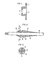
- FIGS. 1 to 3 An exemplary embodiment of a multi-core electrical line provided with the new kink protection sleeve, including the corresponding introduction into the housing of an electrical device, is shown in FIGS. 1 to 3.
- Fig. 1 shows in section the wall 1 of the housing of an electrical device in which a bore 2 is provided for the introduction of an electrical line and a corresponding kink protection sleeve.
- the bore 2 is located in a cylindrical insertion of the housing wall, which merges into the collar 4.
- the multi-core electrical line 10 is provided with the anti-kink bushing 11, which, for example, is manufactured separately and then pushed onto the line and connected to it in a cohesive manner (for example by gluing) or which is sprayed onto the electrical line and cohesively with the jacket the line is connected.
- the kink protection sleeve is overall torpedo-like and young mushroom-shaped at the front end.
- the hollow stem 12 is penetrated by the line 10 while on this stem the cap-like hat 13 connects. This ends at the groove 1 5, which is delimited on the other side by the cylindrical piece 16 of the kink protection sleeve.
- This is followed by the rear end of the kink protection sleeve, which is similar in area 17 or tapered in the manner of an expiring e-function.
- Fig. 3 shows a section of the anti-kink sleeve along the section line A - A. This sectional view shows that the cap-like hat is provided with slots 18 extending in parallel to the axis of the anti-kink sleeve and that the individual areas of the hat over webs 14 on the Support stick 12.
Landscapes
- Engineering & Computer Science (AREA)
- Architecture (AREA)
- Civil Engineering (AREA)
- Structural Engineering (AREA)
- Insulated Conductors (AREA)
- Insulating Bodies (AREA)
- Insertion, Bundling And Securing Of Wires For Electric Apparatuses (AREA)
- Laying Of Electric Cables Or Lines Outside (AREA)
- Cable Accessories (AREA)
- Insulators (AREA)
- Non-Insulated Conductors (AREA)
Abstract
Description
Die Erfindung liegt auf dem Gebiet der Energieversorgung ortsveränderlicher elektrischer Geräte und ist bei der konstruktiven Ausgestaltung einer Knickschutztülle anzuwenden, die am Ende einer in das Gerät einzuführenden flexiblen elektrischen Leitung angeordnet ist.The invention is in the field of energy supply for portable electrical devices and is to be used in the structural design of an anti-kink sleeve which is arranged at the end of a flexible electrical line to be inserted into the device.
Mit Rücksicht auf häufige Biegebeanspruchungen, denen flexible elektrische Leitungen an der Stelle der Einführung in ein ortsveränderliches Gerät ausgesetzt sind, werden die Leitungen an dieser Stelle mit einer im Gerät verankerten Knickschutztülle versehen. Eine bekannte Knickschutztülle besteht aus plastischem oder elastomerem Material und ist fest mit der Leitung verbunden. Um diese Knickschutztülle auch an Geräten montieren zu können, bei denen an der Anschlußstelle im Gehäuse keine Trennebene, sondern nur ein rundum von der Gehäusewandung umgebenes Loch vorliegt, ist die Knickschutztülle mit einer umlaufenden Aussparung versehen, in der ein elastisch federnder Ring aus mechanisch festem Isoliermaterial angebracht ist; dieser Ring weist eine umlaufende, der Aufnahme der Wandung des Gehäuses dienende Ausnehmung auf.(DE-OS 29 22 655). Diese zweiteilige Ausgestaltung der Knickschutztülle bedingt einen entsprechenden Fertigungs- und Montageaufwand.In view of frequent bending stresses to which flexible electrical cables are exposed at the point of insertion into a portable device, the cables are provided with an anti-kink sleeve anchored in the device. A known kink protection sleeve is made of plastic or elastomeric material and is firmly connected to the line. In order to be able to mount this anti-kink sleeve on devices where there is no parting plane at the connection point in the housing, but only a hole all around the housing wall, the anti-kink sleeve is provided with a circumferential recess in which an elastically resilient ring made of mechanically strong insulating material is appropriate; this ring has a circumferential recess which serves to receive the wall of the housing (DE-OS 29 22 655). This two-part design of the kink protection sleeve requires a corresponding manufacturing and assembly effort.
Ausgehend von einer flexiblen elektrischen Leitung, die zur Einführung in ein ortsveränderliches elektrisches Gerät (Haushaltsgerät, Bohr- und Schneidwerkzeug) an einem Ende mit einer fest aufsitzenden, gleichzeitig als Zugabfangung dienenden Knickschutztülle aus plastischem oder elastomerem Material versehen ist, wobei diese Knickschutztülle mittels einer umfänglichen Ausnehmung in einer Bohrung einer Gehäusewand des Gerätes verankerbar ist, liegt der Erfindung die Aufgabe zugrunde, die Knickschutztülle konstruktiv so zu verändern, daß sie einteilig ausgebildet und somit durch einen einzigen Spritzvorgang herstellbar ist.Starting from a flexible electrical cable, which for insertion into a portable electrical device (household appliance, drilling and cutting tool) at one end with a firmly seated, At the same time serving as strain relief anti-kink sleeve made of plastic or elastomeric material, this anti-kink sleeve can be anchored by means of a circumferential recess in a bore of a housing wall of the device, the invention has for its object to constructively change the anti-kink sleeve so that it is formed in one piece and thus can be produced by a single injection process.
Zur Lösung dieser Aufgabe ist gemäß der Erfindung vorgesehen, daß die Ausnehmung aus einer Nut besteht, deren Breite der Dicke der Gehäusewand entspricht, daß der Durchmesser der Knickschutztülle beiderseits der Nut größer ist als der Durchmesser der Bohrung in der Gehäusewand und daß das vordere, auf der einen Seite der umfänglichen Nut liegende Ende der Knickschutztülle jungpilzartig ausgebildet ist, wobei sich der kuppenartige Hut über am Umfang gleichmäßig verteilte Stege auf dem Stiel abstützt.To solve this problem it is provided according to the invention that the recess consists of a groove whose width corresponds to the thickness of the housing wall, that the diameter of the anti-kink sleeve on both sides of the groove is larger than the diameter of the bore in the housing wall and that the front one one end of the circumferential groove, the end of the anti-kink bushing is formed like a young mushroom, the dome-like hat being supported on the stem via webs evenly distributed over the circumference.
Durch diese Ausgestaltung der Knickschutztülle ist eine radiale Elastizität des vorderen Endes der Knickschutztülle gegeben, so daß beim Einschieben der mit der Knickschutztülle versehenen elektrischen Leitung in die Bohrung einer Gehäusewand die Nut der Knickschutztülle unmittelbar in die an die Bohrung angrenzenden Bereiche der Seitenwand einrasten kann. Damit übernimmt die einstückig ausgebildete Knickschutztülle neben den Funktionen des Knickschutzes und der Zugabfangung der elektrischen Leitung auch unmittelbar die Funktion der örtlichen Fixierung der elektrischen Leitung. Weiterhin sind sowohl der Herstellungs- als auch der Montageaufwand auf ein Minimum reduziert.This configuration of the anti-kink sleeve provides a radial elasticity of the front end of the anti-kink sleeve, so that when the electrical line provided with the anti-kink sleeve is inserted into the bore of a housing wall, the groove of the anti-kink sleeve can snap directly into the areas of the side wall adjacent to the bore. In addition to the functions of the kink protection and strain relief of the electrical line, the one-piece anti-kink sleeve also directly takes on the function of locally fixing the electrical line. Furthermore, both the manufacturing and assembly costs are reduced to a minimum.
In Weiterbildung der Erfindung kann die radiale Elastizität des einen Endes der Knickschutztülle dadurch verbessert werden, daß der kuppenartige Hut mit parallel zur Achse der Knickschutztülle verlaufenden Schlitzen versehen ist. Hinsichtlich der Funktion des Knickschutzes empfiehlt sich im übrigen eine solche Ausgestaltung der Knickschutztülle, bei der das rückwärtige Ende der Knickschutztülle ähnlich einer auslaufenden e-Funktion verjüngt ist. Dabei kann es von Vorteil sein, daß der unmittelbar an die ringförmige Nut angrenzende Bereich dieses Endes der Knickschutztülle zunächst zylindrisch, ausgebildet ist, um eine Abstützung der Knickschutztülle in diesem Bereich in einer entsprechenden Ausnehmung der Gehäusewand sicherzustellen.In a further development of the invention, the radial elasticity of one end of the anti-kink sleeve can thereby be improved that the dome-like hat is provided with slots running parallel to the axis of the kink protection sleeve. With regard to the function of the kink protection, it is recommended that the kink protection sleeve be designed in such a way that the rear end of the kink protection sleeve is tapered like an e-function that is running out. It may be advantageous that the area of this end of the kink protection sleeve directly adjacent to the annular groove is initially cylindrical, in order to ensure that the kink protection sleeve is supported in this area in a corresponding recess in the housing wall.
Ein Ausführungsbeispiel einer mit der neuen Knickschutztülle versehenen mehradrigen elektrischen Leitung einschließlich der entsprechenden Einführung in das Gehäuse eines elektrischen Gerätes ist in den Figuren 1 bis 3 dargestellt.An exemplary embodiment of a multi-core electrical line provided with the new kink protection sleeve, including the corresponding introduction into the housing of an electrical device, is shown in FIGS. 1 to 3.
Fig. 1 zeigt im Ausschnitt die Wand 1 des Gehäuses eines elektrischen Gerätes, in der eine Bohrung 2 zur Einführung einer elektrischen Leitung sowie einer entsprechenden Knickschutztülle vorgesehen ist. Die Bohrung 2 befindet sich dabei in einer zylindrischen Einführung der Gehäusewand, die in den Kragen 4 übergeht.Fig. 1 shows in section the
Gemäß Fig. 2 ist die mehradrige elektrische Leitung 10 mit der Knickschutztülle 11 versehen, die beispielsweise getrennt hergestellt und anschließend auf die Leitung aufgeschoben und mit dieser stoffschlüssig (beispielsweise durch Verkleben) verbunden ist oder die auf die elektrische Leitung aufgespritzt und dabei stoffschlüssig mit dem Mantel der Leitung verbunden ist. Die Knickschutztülle ist insgesamt gesehen torpedoartig ausgebildet und am vorderen Ende jungpilzartig gestaltet. Dabei wird der hohle Stiel 12 von der Leitung 10 durchsetzt, während an diesen Stiel der kuppenartige Hut 13 anschließt. Dieser endet an der Nut 15, die auf der anderen Seite von dem zylindrischen Stück 16 der Knickschutztülle begrenzt ist. Hieran schließt sich das rückwärtige Ende der Knickschutztülle an, das im Bereich 17 ähnlich oder nach Art einer auslaufenden e-Funktion verjüngt ist.According to FIG. 2, the multi-core
Fig. 3 zeigt einen Schnitt der Knickschutztülle längs der Schnittlinie A - A. Diese Schnittdarstellung gibt zu erkennen, daß der kuppenartige Hut mit in parallel zur Achse der Knickschutztülle verlaufenden Schlitzen 18 versehen ist und daß sich die einzelnen Bereiche des Hutes über Stege 14 auf dem Stiel 12 abstützen.Fig. 3 shows a section of the anti-kink sleeve along the section line A - A. This sectional view shows that the cap-like hat is provided with
Claims (3)
Priority Applications (1)
| Application Number | Priority Date | Filing Date | Title |
|---|---|---|---|
| AT82730041T ATE9748T1 (en) | 1981-04-06 | 1982-03-23 | ELECTRICAL CABLE WITH ANTI-KIND SLEEVES. |
Applications Claiming Priority (2)
| Application Number | Priority Date | Filing Date | Title |
|---|---|---|---|
| DE3114419 | 1981-04-06 | ||
| DE19813114419 DE3114419A1 (en) | 1981-04-06 | 1981-04-06 | ELECTRIC CABLE WITH ANTI-KIND PROTECTION |
Publications (2)
| Publication Number | Publication Date |
|---|---|
| EP0063536A1 true EP0063536A1 (en) | 1982-10-27 |
| EP0063536B1 EP0063536B1 (en) | 1984-10-03 |
Family
ID=6129812
Family Applications (1)
| Application Number | Title | Priority Date | Filing Date |
|---|---|---|---|
| EP82730041A Expired EP0063536B1 (en) | 1981-04-06 | 1982-03-23 | Electrical conductor with a protecting sleeve against bending |
Country Status (5)
| Country | Link |
|---|---|
| EP (1) | EP0063536B1 (en) |
| AT (1) | ATE9748T1 (en) |
| DE (2) | DE3114419A1 (en) |
| ES (1) | ES272676Y (en) |
| PT (1) | PT74698B (en) |
Cited By (2)
| Publication number | Priority date | Publication date | Assignee | Title |
|---|---|---|---|---|
| FR2547452A1 (en) * | 1983-06-09 | 1984-12-14 | Renault | Bulkhead lead-in grommet for an electrical cable |
| EP1689057A1 (en) * | 2005-02-03 | 2006-08-09 | Neutrik Aktiengesellschaft | Antikink device for an electrical cable |
Families Citing this family (5)
| Publication number | Priority date | Publication date | Assignee | Title |
|---|---|---|---|---|
| DE29922040U1 (en) | 1999-12-15 | 2000-03-30 | protec Kabel Produktion GmbH, 98574 Schmalkalden | Coupling for holding electrical cables, lines and hoses |
| DE102008002616A1 (en) * | 2008-06-24 | 2009-12-31 | Robert Bosch Gmbh | Cable grommet for hand tool |
| DE102011056780A1 (en) * | 2011-12-21 | 2013-06-27 | Balluff Gmbh | Electric device e.g. distance sensor, has case positioned in housing inner space and comprising case inner space by which cable is conducted, where case inner space is connected with cable and wall, which surrounds feedthrough space |
| US9769551B2 (en) | 2014-12-31 | 2017-09-19 | Skullcandy, Inc. | Method of connecting cable to headphone, and headphone formed using such methods |
| DE102016109055A1 (en) | 2016-05-17 | 2017-11-23 | Deutsches Zentrum für Luft- und Raumfahrt e.V. | Free piston device and method for operating a free piston device |
Citations (4)
| Publication number | Priority date | Publication date | Assignee | Title |
|---|---|---|---|---|
| US2115495A (en) * | 1936-05-16 | 1938-04-26 | Gen Electric | Bushing |
| US2727088A (en) * | 1954-03-23 | 1955-12-13 | Gen Electric | Strain relief for electric cords |
| US3243835A (en) * | 1963-04-18 | 1966-04-05 | Gen Motors Corp | Bushing for electrical lead |
| FR2397084A1 (en) * | 1977-07-06 | 1979-02-02 | Inst Francais Du Petrole | Suspension point for submarine cables and lines - provides progressive stiffening of cable using thermoplastic sleeves |
-
1981
- 1981-04-06 DE DE19813114419 patent/DE3114419A1/en not_active Withdrawn
-
1982
- 1982-03-23 AT AT82730041T patent/ATE9748T1/en not_active IP Right Cessation
- 1982-03-23 DE DE8282730041T patent/DE3260867D1/en not_active Expired
- 1982-03-23 EP EP82730041A patent/EP0063536B1/en not_active Expired
- 1982-04-02 PT PT74698A patent/PT74698B/en unknown
- 1982-04-05 ES ES1982272676U patent/ES272676Y/en not_active Expired
Patent Citations (4)
| Publication number | Priority date | Publication date | Assignee | Title |
|---|---|---|---|---|
| US2115495A (en) * | 1936-05-16 | 1938-04-26 | Gen Electric | Bushing |
| US2727088A (en) * | 1954-03-23 | 1955-12-13 | Gen Electric | Strain relief for electric cords |
| US3243835A (en) * | 1963-04-18 | 1966-04-05 | Gen Motors Corp | Bushing for electrical lead |
| FR2397084A1 (en) * | 1977-07-06 | 1979-02-02 | Inst Francais Du Petrole | Suspension point for submarine cables and lines - provides progressive stiffening of cable using thermoplastic sleeves |
Cited By (4)
| Publication number | Priority date | Publication date | Assignee | Title |
|---|---|---|---|---|
| FR2547452A1 (en) * | 1983-06-09 | 1984-12-14 | Renault | Bulkhead lead-in grommet for an electrical cable |
| EP1689057A1 (en) * | 2005-02-03 | 2006-08-09 | Neutrik Aktiengesellschaft | Antikink device for an electrical cable |
| US7314999B2 (en) | 2005-02-03 | 2008-01-01 | Neutrik Aktiengesellschaft | Antikink device for an electrical cable |
| CN1862888B (en) * | 2005-02-03 | 2011-10-12 | 努伊特里克公开股份有限公司 | Antikink device for an electrical cable, electrical with the device and processing method thereof |
Also Published As
| Publication number | Publication date |
|---|---|
| ES272676U (en) | 1983-12-01 |
| DE3114419A1 (en) | 1982-10-21 |
| EP0063536B1 (en) | 1984-10-03 |
| ATE9748T1 (en) | 1984-10-15 |
| ES272676Y (en) | 1984-06-16 |
| PT74698A (en) | 1982-05-01 |
| DE3260867D1 (en) | 1984-11-08 |
| PT74698B (en) | 1983-10-28 |
Similar Documents
| Publication | Publication Date | Title |
|---|---|---|
| EP0350835A3 (en) | Electrical connector | |
| EP0521189A1 (en) | Electrical terminal for a solar module | |
| DE3604896A1 (en) | COAXIAL ANGLE PLUG | |
| EP0396931A3 (en) | Terminal housing for multipolar electrical plug connector | |
| EP0653322B1 (en) | Pivot shaft for a vehicle sunvisor | |
| GB1535668A (en) | Junction device | |
| EP0063536A1 (en) | Electrical conductor with a protecting sleeve against bending | |
| DE2835400C2 (en) | Connector for connecting two electrical lines with at least two wires | |
| DE2511294B2 (en) | Rotary coupling | |
| ES296612U (en) | Nuclear fuel assembly with replaceable fuel elements | |
| DE3436635C1 (en) | Gas-tight and moisture-proof connection with tension relief, for coaxial cables which are inserted into connecting fittings | |
| DE2745887A1 (en) | ELECTRIC CONNECTOR HOUSING | |
| DE3762907D1 (en) | CONSTRUCTION, CONSISTING OF AT LEAST TWO CONSTRUCTION PARTS, CONNECTED BY CONNECTORS. | |
| DE478570C (en) | Slot clamp for electrical wiring systems | |
| DE2817170C2 (en) | Internal vibrator | |
| DE7004948U (en) | PROTECTIVE CAP TO SECURE PUSH-BUTTON SWITCHES OR DGL. AGAINST DUST, WET, OR THE LIKE. | |
| DE60116245T2 (en) | Clamp for electrical cables | |
| DE2930413A1 (en) | ELECTRICAL THROUGH CONNECTOR AND PRE-WIRED PARTITION SYSTEM WITH SUCH A CONNECTOR | |
| DE8218120U1 (en) | Cover cap for a plug-in device | |
| DE7519930U (en) | Spark plug connector in angled design | |
| DE3208307A1 (en) | THREE-PHASE GENERATOR, ESPECIALLY AS ON-LINE POWER GENERATOR | |
| DE7134976U (en) | NON-CLOCKABLE EQUIPMENT CONNECTOR WITH ELECTRIC HOSE | |
| DE1765175B1 (en) | INTRODUCTION FOR AN ELECTRIC CABLE WITH A METALLIC EXTERNAL ARMING IN THE HOUSING OF ELECTRICAL EQUIPMENT | |
| DE3046389A1 (en) | PROTECTIVE TERMINAL | |
| DE7009798U (en) | SPLIT CABLE JOINT WITH CABLE CLAMP. |
Legal Events
| Date | Code | Title | Description |
|---|---|---|---|
| PUAI | Public reference made under article 153(3) epc to a published international application that has entered the european phase |
Free format text: ORIGINAL CODE: 0009012 |
|
| AK | Designated contracting states |
Designated state(s): AT CH DE FR GB IT NL SE |
|
| 17P | Request for examination filed |
Effective date: 19830309 |
|
| ITF | It: translation for a ep patent filed | ||
| GRAA | (expected) grant |
Free format text: ORIGINAL CODE: 0009210 |
|
| AK | Designated contracting states |
Designated state(s): AT CH DE FR GB IT LI NL SE |
|
| REF | Corresponds to: |
Ref document number: 9748 Country of ref document: AT Date of ref document: 19841015 Kind code of ref document: T |
|
| REF | Corresponds to: |
Ref document number: 3260867 Country of ref document: DE Date of ref document: 19841108 |
|
| ET | Fr: translation filed | ||
| PLBE | No opposition filed within time limit |
Free format text: ORIGINAL CODE: 0009261 |
|
| STAA | Information on the status of an ep patent application or granted ep patent |
Free format text: STATUS: NO OPPOSITION FILED WITHIN TIME LIMIT |
|
| 26N | No opposition filed | ||
| PGFP | Annual fee paid to national office [announced via postgrant information from national office to epo] |
Ref country code: AT Payment date: 19860228 Year of fee payment: 5 |
|
| PGFP | Annual fee paid to national office [announced via postgrant information from national office to epo] |
Ref country code: NL Payment date: 19860331 Year of fee payment: 5 |
|
| PG25 | Lapsed in a contracting state [announced via postgrant information from national office to epo] |
Ref country code: AT Effective date: 19870323 |
|
| PG25 | Lapsed in a contracting state [announced via postgrant information from national office to epo] |
Ref country code: SE Effective date: 19870324 |
|
| PG25 | Lapsed in a contracting state [announced via postgrant information from national office to epo] |
Ref country code: LI Effective date: 19870331 Ref country code: CH Effective date: 19870331 |
|
| PG25 | Lapsed in a contracting state [announced via postgrant information from national office to epo] |
Ref country code: NL Effective date: 19871001 |
|
| NLV4 | Nl: lapsed or anulled due to non-payment of the annual fee | ||
| GBPC | Gb: european patent ceased through non-payment of renewal fee | ||
| PG25 | Lapsed in a contracting state [announced via postgrant information from national office to epo] |
Ref country code: FR Free format text: LAPSE BECAUSE OF NON-PAYMENT OF DUE FEES Effective date: 19871130 |
|
| REG | Reference to a national code |
Ref country code: CH Ref legal event code: PL |
|
| PG25 | Lapsed in a contracting state [announced via postgrant information from national office to epo] |
Ref country code: DE Effective date: 19871201 |
|
| REG | Reference to a national code |
Ref country code: FR Ref legal event code: ST |
|
| PG25 | Lapsed in a contracting state [announced via postgrant information from national office to epo] |
Ref country code: GB Effective date: 19881121 |
|
| EUG | Se: european patent has lapsed |
Ref document number: 82730041.9 Effective date: 19880215 |