EP0063287B1 - Schutzvorrichtung für Rohre - Google Patents
Schutzvorrichtung für Rohre Download PDFInfo
- Publication number
- EP0063287B1 EP0063287B1 EP82102816A EP82102816A EP0063287B1 EP 0063287 B1 EP0063287 B1 EP 0063287B1 EP 82102816 A EP82102816 A EP 82102816A EP 82102816 A EP82102816 A EP 82102816A EP 0063287 B1 EP0063287 B1 EP 0063287B1
- Authority
- EP
- European Patent Office
- Prior art keywords
- means according
- pipes
- moisture
- support
- containers
- Prior art date
- Legal status (The legal status is an assumption and is not a legal conclusion. Google has not performed a legal analysis and makes no representation as to the accuracy of the status listed.)
- Expired
Links
- 230000001681 protective effect Effects 0.000 claims description 21
- 238000001035 drying Methods 0.000 claims 4
- 238000010521 absorption reaction Methods 0.000 claims 1
- 230000001788 irregular Effects 0.000 claims 1
- 238000010792 warming Methods 0.000 claims 1
- 238000003466 welding Methods 0.000 claims 1
- 239000002274 desiccant Substances 0.000 description 13
- JEIPFZHSYJVQDO-UHFFFAOYSA-N iron(III) oxide Inorganic materials O=[Fe]O[Fe]=O JEIPFZHSYJVQDO-UHFFFAOYSA-N 0.000 description 13
- 238000011161 development Methods 0.000 description 3
- 230000018109 developmental process Effects 0.000 description 3
- 238000004519 manufacturing process Methods 0.000 description 3
- 229910000831 Steel Inorganic materials 0.000 description 2
- 230000015572 biosynthetic process Effects 0.000 description 2
- 239000000969 carrier Substances 0.000 description 2
- 239000000463 material Substances 0.000 description 2
- 239000010959 steel Substances 0.000 description 2
- 244000089486 Phragmites australis subsp australis Species 0.000 description 1
- 238000004026 adhesive bonding Methods 0.000 description 1
- 239000012790 adhesive layer Substances 0.000 description 1
- 239000013043 chemical agent Substances 0.000 description 1
- 239000003795 chemical substances by application Substances 0.000 description 1
- 238000009833 condensation Methods 0.000 description 1
- 230000005494 condensation Effects 0.000 description 1
- 230000007797 corrosion Effects 0.000 description 1
- 238000005260 corrosion Methods 0.000 description 1
- 230000003247 decreasing effect Effects 0.000 description 1
- 238000009826 distribution Methods 0.000 description 1
- 238000007689 inspection Methods 0.000 description 1
- 239000010410 layer Substances 0.000 description 1
- 238000012544 monitoring process Methods 0.000 description 1
- 230000003287 optical effect Effects 0.000 description 1
- 238000007789 sealing Methods 0.000 description 1
- 238000009958 sewing Methods 0.000 description 1
- 239000002356 single layer Substances 0.000 description 1
- 238000003860 storage Methods 0.000 description 1
Images

Classifications
-
- B—PERFORMING OPERATIONS; TRANSPORTING
- B65—CONVEYING; PACKING; STORING; HANDLING THIN OR FILAMENTARY MATERIAL
- B65D—CONTAINERS FOR STORAGE OR TRANSPORT OF ARTICLES OR MATERIALS, e.g. BAGS, BARRELS, BOTTLES, BOXES, CANS, CARTONS, CRATES, DRUMS, JARS, TANKS, HOPPERS, FORWARDING CONTAINERS; ACCESSORIES, CLOSURES, OR FITTINGS THEREFOR; PACKAGING ELEMENTS; PACKAGES
- B65D59/00—Plugs, sleeves, caps, or like rigid or semi-rigid elements for protecting parts of articles or for bundling articles, e.g. protectors for screw-threads, end caps for tubes or for bundling rod-shaped articles
- B65D59/06—Caps
-
- Y—GENERAL TAGGING OF NEW TECHNOLOGICAL DEVELOPMENTS; GENERAL TAGGING OF CROSS-SECTIONAL TECHNOLOGIES SPANNING OVER SEVERAL SECTIONS OF THE IPC; TECHNICAL SUBJECTS COVERED BY FORMER USPC CROSS-REFERENCE ART COLLECTIONS [XRACs] AND DIGESTS
- Y10—TECHNICAL SUBJECTS COVERED BY FORMER USPC
- Y10S—TECHNICAL SUBJECTS COVERED BY FORMER USPC CROSS-REFERENCE ART COLLECTIONS [XRACs] AND DIGESTS
- Y10S138/00—Pipes and tubular conduits
- Y10S138/06—Corrosion
Definitions
- the invention relates to a protective device for pipes, the pipe ends of which are provided with a thread, according to the preamble of claim 1.
- Pipes especially threaded oilfield pipes, are often exposed to various climatic conditions due to long transport routes and storage. As a result, they tend to rust on the inside.
- the tubes are usually provided with protective caps at the ends to protect the threads.
- closed protective caps and protective plugs are often used, which completely close the pipe on both sides. This in turn has the consequence that condensation forms with temperature fluctuations, which can increase the rust formation.
- Chemical agents are known which have the property of absorbing moisture from the environment. Such agents are commonly called desiccants. It is also known to pack such desiccants in bags to protect the pipes and then to push these bags into the pipes, where they are stored just behind the pipe ends.
- DE-U-1 812 073 and DE-U-1 820 105 show a sealing plug for the ends of steel pipes, which has a cavity open to the inside of the steel pipes, in which a drying agent for binding moisture is arranged.
- a tape is known on which tablets are arranged in packaged form and which is provided with moisture indicators with a color display.
- This tape has an adhesive layer on the side opposite the tablets and serves to keep closed cavities, for example containers for transporting sensitive measuring instruments, dry.
- the present invention has for its object to provide a protective device for pipes so that corrosion, in particular rusting of the inner wall of the pipes is safely avoided and the previous, cumbersome, complex and expensive inspection can be dispensed with.
- the design according to the invention makes it possible in a simple manner to introduce desiccants into pipes in such a way that reliable protection against moisture and thus against rust formation along the entire pipe is ensured.
- the desiccant can be distributed in portions, filled into containers, along the inside of the tube with short, longer, even or uneven intervals. A continuous distribution along the inside of the pipe is also possible.
- the handling and attachment of the device according to the invention is possible without essential aids and can also be done by auxiliary staff.
- the thread protection device once screwed on can remain in the installed position due to the design according to the invention.
- the inside of the pipe is checked by monitoring the moisture with the aid of a suitable moisture indicator.
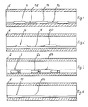
- reference numeral 2 denotes a pipe in which rust protection devices 4, 6, 8, 10 and 25 are arranged.
- the rust protection device 4 according to FIG. Consists of a two-layer strip 12, in which cushions 14 are worked out, between which there are constrictions 16 and in which there is desiccant.
- the rust protection device 6 according to FIG. 2 consists of a single-layer strip 18, on which cushions 20 are applied at certain intervals, for example by sewing, gluing or the like. Desiccant is again present in the pillows.
- the rust protection device 8 according to FIG. 3 consists of bags 22 filled with desiccant, which are fastened at a distance from one another on a band or a cord 24, for example by tying or clipping.
- the rust protection device 25 consists of a fleece strip 27 in which the desiccant is sewn in the form of tablets 29.
- the cushions 14 and 20 and the bags 22 and the tablets 29 can also be arranged in an unevenly distributed manner apart from at regular intervals. It is also conceivable to arrange them from the pipe center to the pipe ends with increasing or decreasing distances (see FIG. 5).
- the rust protection device 10 consists of a hose 26 filled with desiccant, the ends of which are closed.
- a material that is permeable to moisture for example a fleece, is used as the material for the pillows, bags and the tube.
- the rust protection devices 4, 6, 8, 10 and 25 are attached to the pipe ends.
- the fastening takes place by means of the thread protection devices closing the pipe ends in the form of protective caps 30 or protective plugs 32, for example with the aid of hooks 34 arranged on the caps and eyelets 36 attached to the rust protection devices, cf. Fig. 5; Suitable clamping devices (not shown) can also be used.
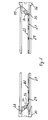
- FIG. 6 shows a tube 40 which has an external thread 42 at one end and an internal thread 44 at the other end.
- a protective cap 46 is screwed onto the external thread and a protective plug 48 onto the internal thread.
- the protective cap 46 has a jacket 52 provided with an internal thread 50 and a cup-shaped insert 54 with a bottom 56 which is connected to the jacket 52 via an annular web part 58 covering the tube edge. Grooves 60 are formed in the web part for attaching a tool.
- the protective plug 48 is in the form of a cup-shaped insert with a jacket 62 and a bottom 64.
- the jacket 62 has an external thread 65.
- a moisture indicator device 68 or 70 is arranged in the bottom 56 of the protective cap and also in the bottom 64 of the protective plug. It is normally sufficient if such a moisture indicator is arranged in only one of the trays 56 and 64.
- the moisture indicator device is a simple moisture indicator 71 which is arranged in the viewing window 72 of a threaded plug 74 which is screwed into the bottom of the protective device.
- the moisture indicator is preferably arranged interchangeably.
- the moisture indicator can also be an electrical moisture measuring device, to which a warning device can additionally be connected in order to indicate acoustically and, of course, optically that a certain moisture content has been reached.
- the protective cap 46 and the protective plug 48 can, unlike in the drawing, also have bottoms which lie approximately in the plane of the web part 58 or the ring flanges 67.
Landscapes
- Engineering & Computer Science (AREA)
- Mechanical Engineering (AREA)
- Buffer Packaging (AREA)
- Testing Resistance To Weather, Investigating Materials By Mechanical Methods (AREA)
- Packages (AREA)
Description
- Die Erfindung betrifft eine Schutzvorrichtung für Rohre, deren Rohrenden mit einem Gewinde versehen sind, gemäß dem Oberbegriff des Anspruchs 1.
- Rohre, insbesondere mit Gewinde versehene Ölfeldrohre, werden häufig durch lange Transportwege und Lagerung verschiedenen klimatischen Bedingungen ausgesetzt. Sie neigen infolgedessen vor allem an der Innenseite zur Rostbildung. Die Rohre werden üblicherweise an den Enden mit Schutzkappen versehen, um die Gewinde zu schützen. Um ferner zu verhindern, daß Fremdkörper oder Regenwasser in das Innere der Rohre gelangt, werden häufig geschlossene Schutzkappen und Schutzstopfen verwendet, die das Rohr vollständig an beiden Seiten verschließen. Dies wiederum hat zur Folge, daß sich bei Temperaturschwankungen Schwitzwasser bildet, das die Rostbildung verstärken kann. Es sind chemische Mittel bekannt, die die Eigenschaft haben, Feuchtigkeit aus der Umgebung aufzunehmen. Solche Mittel werden allgemein Trockenmittel genannt. Es ist auch bekannt, zum Schutz der Rohre solche Trockenmittel in Beutel abzupacken und diese Beutel dann in die Rohre zu schieben, wo sie kurz hinter den Rohrenden lagern.
- Die DE-U-1 812 073 undDE-U-1 820 105 zeigen einen Verschlußstopfen für die Enden von Stahlrohren, der einen zum Inneren der Stahlrohre hin offenen Hohlraum aufweist, in dem ein Trockenmittel zur Bindung von Feuchtigkeit angeordnet ist.
- Es hat sich nun gezeigt, daß diese bekannten Schutzeinrichtungen nicht ausreichen, die Rohre vor Rostbildung zu schützen. Es hat sich nämlich gezeigt, daß in Rohren, insbesondere größerer Länge, die Feuchtigkeit von dem Trockenmittel' nur aus der näheren Umgebung der Trockenmittel aufgenommen wird, und daß die weiter innen liegenden Innenrohrflächen rosten. Ferner ist es notwendig, die Rohre von Zeit zu Zeit zu inspizieren. Hierzu werden bisher in recht umständlicher, zeitraubender und teurer Art und Weise jeweils die Schutzkappen und Schutzstopfen abgeschraubt bzw. abgenommen ; das Rohrinnere wird dann optisch überprüft.
- Aus der US-A-3 260 234 ist ein Band bekannt, auf dem Tabletten in abgepackter Form angeordnet sind und das mit Feuchtigkeitsindikatoren mit Farbanzeige versehen ist. Dieses Band weist auf der den Tabletten gegenüberliegenden Seite eine Klebeschicht auf und dient dazu, abgeschlossene Hohlräume, beispielsweise Behälter zum Transport empfindlicher Meßinstrumente, trockenzuhalten.
- Der vorliegenden Erfindung liegt die Aufgabe zugrunde, eine Schutzeinrichtung für Rohre so auszubilden, daß eine Korrosion, insbesondere ein Rosten der Innenwandung der Rohre sicher vermieden ist und auf die bisherige, umständliche, aufwendige und teure Inspektion verzichet werden kann.
- Diese Aufgabe wird durch die im Kennzeichen des Anspruchs 1 angegebene Ausbildung gelöst.
- Durch die erfindungsgemäße Ausbildung ist es auf einfache Weise möglich, Trockenmittel definiert in Rohre so einzubringen, daß ein sicherer Schutz gegen Feuchtigkeit und damit gegen Rostbildung entlang des ganzen Rohres gewährleistet ist. Die Verteilung des Trockenmittels kann portionsweise, abgefüllt in Behältnisse, entlang des Rohrinneren mit kurzen, längeren, gleichmäßigen oder ungleichmäßigen Abständen erfolgen. Eine kontinuierliche Verteilung entlang des Rohrinneren ist auch möglich. Die Handhabung und Anbringung der erfindungsgemäßen Einrichtung ist ohne wesentliche Hilfsmittel möglich und kann auch von Hilfskräften erfolgen.
- Durch die erfindungsgemäße Ausbildung kann die einmal aufgeschraubte Gewindeschutzvorrichtung in der Einbaulage verbleiben. Die Kontrolle des Rohrinneren erfolgt durch Überwachung der Feuchtigkeit mit Hilfe einer geeigneten Feuchtigkeitsanzeigeeinrichtung.
- Zweckmäßige und vorteilhafte Weiterbildungen der erfindungsgemäßen Lösung sind in den Unteransprüchen gekennzeichnet.
- Zweckmäßig und einfach herzustellende Behältnisse und Träger sowie deren Verbindung und Anordnung sind in den Ansprüchen 2 bis 5 und 9 angegeben.
- Die Weiterbildungen nach den Ansprüchen 6, 7 und 8 geben besonders einfach herstellbare und einsetzbare Träger mit Trockenmittel wieder.
- In den Unteransprüchen 10 bis 12 sind zweckmäßige und vorteilhafte Ausbildungen und Anordnungen von Feuchtigkeitsanzeige-einrichtungen angegeben. Diese Anzeigeeinrichtungen sind preiswert in der Herstellung, einfach zu installieren und geben den Feuchtigkeitsgehalt mit ausreichender Genauigkeit an. Eine Meß- und Warneinrichtung kann ebenfalls eingebaut sein, die bei Erreichen eines vorbestimmten Feuchtigkeitsgrades ein optisches oder akustisches Warnsignal abgibt. Durch diese erfindungsgemäße Weiterbildung entfällt das aufwendige und damit teure Abnehmen der Gewindeschutzvorrichtung zwecks Inspektion des Rohrinneren ; mit Hilfe der eingebauten Feuchtigkeitsanzeigeeinrichtung kann sofort erkannt werden, ob im Rohrinneren ein die Rostbildung zulassender Feuchtigkeitsgrad herrscht oder nicht.
- Die Erfindung soll nun anhand der beigefügten Zeichnung, in der einige Ausführungsbeispiele dargestellt sind, näher erläutert werden.
- Es zeigt
- Figuren 1 bis 5 verschiedene Ausführungsformen der erfindungsgemäßen Schutzvorrichtung für Rohre und
- Figur 6 eine erfindungsgemäß ausgebildete Einrichtung zur Anzeige der Feuchtigkeit in einem Rohr.
- In den Fig. 1 bis 5 ist mit dem Bezugszeichen 2 ein Rohr bezeichnet, in dem Rostschutzeinrichtungen 4, 6, 8, 10 und 25 angeordnet sind. Die Rostschutzeinrichtung 4 nach Fig. besteht aus einem zweilagigen Streifen 12, in dem Kissen 14 ausgearbeitet sind, zwischen denen sich Einschnürungen 16 befinden und in denen sich Trockenmittel befindet.
- Die Rostschutzeinrichtung 6 nach Fig. 2 besteht aus einem einlagigen Streifen 18, auf dem Kissen 20 in bestimmten Abständen aufgebracht sind, beispielsweise durch Annähen, Aufkleben oder dergleichen. In den Kissen ist wiederum Trockenmittel vorhanden.
- Die Rostschutzeinrichtung 8 nach Fig. 3 besteht aus mit Trockenmittel gefüllten Beuteln 22, die mit Abstand zueinander an einem Band oder einer Kordel 24 befestigt sind, beispielsweise durch Festbinden oder Anklammern.
- Die Rostschutzeinrichtung 25 nach Fig.5 5 besteht aus einem Vliesstreifen 27, in dem das Trockenmittel in Form von Tabletten 29 eingenäht ist.
- Die Kissen 14 und 20 und die Beutel 22 sowie die Tabletten 29 können außer in gleichmäßigen Abständen auch ungleichmäßig verteilt angeordnet sein. Es ist auch denkbar, sie von der Rohrmitte zu den Rohrenden hin mit zu- oder abnehmenden Abständen (vgl. Fig.5) anzuordnen.
- Die Rostschutzeinrichtung 10 nach Fig.4 besteht aus einem mit Trockenmittel gefüllten Schlauch 26, dessen Enden verschlossen sind.
- Als Material für die Kissen, Beutel und den Schlauch dient ein für Feuchtigkeit durchlässiges Material, beispielsweise ein Vlies.
- Die Rostschutzeinrichtungen 4, 6, 8, 10 und 25 sind an den Rohrenden befestigt. Die Befestigung erfolgt durch die die Rohrenden verschließenden Gewindeschutzvorrichtungen in Form von Schutzkappen 30 oder Schutzstopfen 32, beispielsweise mit Hilfe von an den Kappen angeordneten Haken 34 und an den Rostschutzeinrichtungen angebrachten Ösen 36, vgl. Fig. 5 ; auch geeignete Klemmeinrichtungen (nicht dargestellt) können eingesetzt werden.
- Bei Rohren größeren Durchmessers ist es zweckmäßig, mehrere der Rostschutzeinrichtungen 4, 6, 8, 10 oder 25 in den Rohren nebeneinander anzuordnen.
- Die Fig. 6 zeigt ein Rohr 40, das an einem Ende ein Außengewinde 42 und am anderen Ende ein Innengewinde 44 trägt. Auf das Außengewinde ist eine Schutzkappe 46 und auf das Innengewinde ein Schutzstopfen 48 geschraubt.
- Die Schutzkappe 46 weist einen mit einem Innengewinde 50 versehenen Mantel 52 und einen becherförmigen Einsatz 54 mit einem Boden 56 auf, der mit dem Mantel 52 über einen den Rohrrand überdeckenden, ringförmigen Stegteil 58 verbunden ist. Im Stegteil sind Nuten 60 ausgebildet zum Ansetzen eines Werkzeugs.
- Der Schutzstopfen 48 ist in Form eines becherförmigen Einsatzes ausgebildet mit einem Mantel 62 und einem Boden 64. Der Mantel 62 weist ein Außengewinde 65 auf. Ein Ringflansch 67, in dem Nuten 66 zum Ansetzen eines Werkzeugs ausgebildet sind, überdeckt den Rohrrand.
- Im Boden 56 der Schutzkappe und auch im Boden 64 des Schutzstopfens ist jeweils eine Feuchtigkeitsanzeigeeinrichtung 68 bzw. 70 angeordnet. Es ist normalerweise ausreichend, wenn nur in einem der Böden 56 und 64 eine solche Feuchtigkeitsanzeigeeinrichtung angeordnet ist.
- Die Feuchtigkeitsanzeigeeinrichtung ist in der Zeichnung ein einfacher Feuchtigkeitsindikator 71, der im Sichtfenster 72 eines Gewindestopfens 74 angeordnet ist, der in den Boden der Schutzvorrichtung eingeschraubt ist. Der Feuchtigkeitsindikator ist vorzugsweise austauschbar angeordnet.
- Die Feuchtigkeitsanzeige kann auch ein elektrisches Feuchtigkeitsmeßgerät sein, an das zusätzlich noch eine Warneinrichtung angeschlossen sein kann, um das Erreichen eines bestimmten Feuchtigkeitsgehaltes akustisch und natürlich auch optisch anzuzeigen.
- Die Schutzkappe 46 und der Schutzstopfen 48 können anders als in der Zeichnung dargestellt auch Böden aufweisen, die in etwa in der Ebene des Stegteiles 58 bzw. der Ringflansche 67 liegen.
Claims (12)
Priority Applications (1)
| Application Number | Priority Date | Filing Date | Title |
|---|---|---|---|
| AT82102816T ATE14045T1 (de) | 1981-04-09 | 1982-04-02 | Schutzvorrichtung fuer rohre. |
Applications Claiming Priority (4)
| Application Number | Priority Date | Filing Date | Title |
|---|---|---|---|
| DE3114264 | 1981-04-09 | ||
| DE19813114264 DE3114264C2 (de) | 1981-04-09 | 1981-04-09 | Rostschutzeinrichtung für die Innenfläche von Rohren unter Verwendung eines Trocknungsmittels |
| DE19813114368 DE3114368C2 (de) | 1981-04-09 | 1981-04-09 | Schutzkappe bzw. Schutzstopfen für mit Gewinde versehene Enden von Rohren |
| DE3114368 | 1981-04-09 |
Publications (2)
| Publication Number | Publication Date |
|---|---|
| EP0063287A1 EP0063287A1 (de) | 1982-10-27 |
| EP0063287B1 true EP0063287B1 (de) | 1985-06-26 |
Family
ID=25792558
Family Applications (1)
| Application Number | Title | Priority Date | Filing Date |
|---|---|---|---|
| EP82102816A Expired EP0063287B1 (de) | 1981-04-09 | 1982-04-02 | Schutzvorrichtung für Rohre |
Country Status (3)
| Country | Link |
|---|---|
| US (1) | US4438783A (de) |
| EP (1) | EP0063287B1 (de) |
| DE (1) | DE3264397D1 (de) |
Families Citing this family (6)
| Publication number | Priority date | Publication date | Assignee | Title |
|---|---|---|---|---|
| US5211206A (en) * | 1989-07-07 | 1993-05-18 | Cougar Tools Inc. | Apparatus for securing written information to tubular goods |
| US5303743A (en) * | 1991-05-08 | 1994-04-19 | Vincent Larry W | Thread protection system |
| US5352383A (en) * | 1991-10-18 | 1994-10-04 | Centrax International Corp. | Corrosion inhibitor and sealable thread protector end cap for tubular goods |
| DE20103745U1 (de) * | 2001-03-03 | 2002-07-04 | Fraunhofer-Gesellschaft zur Förderung der angewandten Forschung e.V., 80636 München | Bauteil |
| US20080189869A1 (en) * | 2007-02-08 | 2008-08-14 | 3M Innovative Properties Company | Securing unit |
| US9915433B2 (en) | 2014-05-30 | 2018-03-13 | Amtrol Licensing Inc. | Moisture detecting air cap indicator for expansion tank failure |
Family Cites Families (14)
| Publication number | Priority date | Publication date | Assignee | Title |
|---|---|---|---|---|
| US1705837A (en) * | 1928-04-30 | 1929-03-19 | Rowan Colonel Glenn | Thermostat-controlled alarm |
| US2737205A (en) * | 1952-08-28 | 1956-03-06 | Fullerton Mfg Company | Means for protectively isolating internal pipe surfaces |
| US3052083A (en) * | 1953-12-22 | 1962-09-04 | Piquerez Ervin | Waterproof watchcase with moisture indicator |
| US2716338A (en) * | 1954-04-08 | 1955-08-30 | Welford C Blinn | Button type package humidity indicator |
| US2826222A (en) * | 1954-10-29 | 1958-03-11 | James W Case | Preservative closure |
| US2977993A (en) * | 1957-11-27 | 1961-04-04 | Texas Pipe Line Company | Non-metallic pipe end closure |
| US3085424A (en) * | 1959-11-17 | 1963-04-16 | Ansul Chemical Co | Moisture indicator housing |
| DE1820105U (de) * | 1960-05-13 | 1960-10-20 | Luther Werke Luther & Jordan | Korrosionsschutzorgan fuer lagernde stahlrohre. |
| US3115010A (en) * | 1960-12-12 | 1963-12-24 | Thiokol Chemical Corp | Closure for container |
| US3246758A (en) * | 1963-01-30 | 1966-04-19 | Watsco Inc | Hygrometric indicator for desiccants |
| FR1398104A (fr) * | 1964-03-26 | 1965-05-07 | Participations Et Procedes Ind | éléments déshydratants et leur procédé de fabrication |
| US3260234A (en) * | 1964-12-11 | 1966-07-12 | Gen Dynamics Corp | Desiccant tape |
| SE358383B (de) * | 1967-12-06 | 1973-07-30 | Sandoz Ag | |
| US4124116A (en) * | 1977-02-15 | 1978-11-07 | Mccabe Jr Edward G | Liquid absorbing sectional pack |
-
1982
- 1982-04-02 DE DE8282102816T patent/DE3264397D1/de not_active Expired
- 1982-04-02 EP EP82102816A patent/EP0063287B1/de not_active Expired
- 1982-04-09 US US06/366,981 patent/US4438783A/en not_active Expired - Lifetime
Also Published As
| Publication number | Publication date |
|---|---|
| DE3264397D1 (en) | 1985-08-01 |
| US4438783A (en) | 1984-03-27 |
| EP0063287A1 (de) | 1982-10-27 |
Similar Documents
| Publication | Publication Date | Title |
|---|---|---|
| DE3118878C2 (de) | Prüfröhrchen | |
| EP0590280B1 (de) | Verfahren und Einrichtung zur Ultraschall-Leckage-Ortung | |
| EP0997716A1 (de) | Eintausch-Messsonde zur Messung in Flüssigkeiten | |
| DE10011768A1 (de) | Transportbehälter für Lebewesen | |
| DE1932175B2 (de) | Elektrischer messfuehler zur bestimmung der jeweiligen augen blicklichen fuellhoehe von schuettfaehigem gut | |
| EP0063287A1 (de) | Schutzvorrichtung für Rohre | |
| DE69604609T2 (de) | Seerettungsgerät | |
| DE4205805A1 (de) | Spende-behaelter fuer streifenfoermige materialabschnitte | |
| DE3037826A1 (de) | Probenahmeroehrchen mit verschlusskappen | |
| DE3000201C2 (de) | Vorrichtung zur Bestimmung des Kohlenstoffgehalts in geschmolzenem Metall | |
| DE10065384B4 (de) | Gassensor mit Schutzkappe und Schutzkappe für Gassensor | |
| DE3114264C2 (de) | Rostschutzeinrichtung für die Innenfläche von Rohren unter Verwendung eines Trocknungsmittels | |
| EP0591294B1 (de) | Gas- und/oder flüssigkeitsführende rohrleitung | |
| WO2014012633A1 (de) | Verpackung für ein produkt mit mindestens einem hygroskopischen rieselfähigen feststoff | |
| DE3336335A1 (de) | Einrichtung zur ueberwachung eines behaelters | |
| DE202019104256U1 (de) | Schutzvorrichtung für eine Einrichtung eines Behälters | |
| DE3035902C2 (de) | ||
| DE2802139C3 (de) | Wasserfüll- und Entleerungseinrichtung für Ackerschlepper-Triebradreifen | |
| DE9108467U1 (de) | Element zum gas- und flüssigkeitsdichten Sichern und Überwachen eines Körpers, insbesondere einer Abfalldeponie | |
| DE8110770U1 (de) | Feuchtigkeitsdurchlaessiges mit Trockenmittel gefuelltes Behaeltnis zur Verwendung von Rohren | |
| DE1925660C3 (de) | Flüssigkeitsanzeiger mit Primärmagnet auf einem Schwimmer | |
| AT400947B (de) | Leckwarnsystem | |
| DE3114368A1 (de) | "gewindeschutzvorrichtung fuer rohrenden" | |
| DE2310943A1 (de) | Verfahren und vorrichtung zur pruefung der sicheren funktionsfaehigkeit eines mit einem druckgefaess verbundenen druckanzeigers | |
| DE8110716U1 (de) | Gewindeschutzvorrichtung fuer Rohrenden |
Legal Events
| Date | Code | Title | Description |
|---|---|---|---|
| PUAI | Public reference made under article 153(3) epc to a published international application that has entered the european phase |
Free format text: ORIGINAL CODE: 0009012 |
|
| AK | Designated contracting states |
Designated state(s): AT BE CH DE FR GB IT LU NL SE |
|
| RHK1 | Main classification (correction) |
Ipc: F16L 57/00 |
|
| 17P | Request for examination filed |
Effective date: 19830423 |
|
| ITF | It: translation for a ep patent filed | ||
| GRAA | (expected) grant |
Free format text: ORIGINAL CODE: 0009210 |
|
| AK | Designated contracting states |
Designated state(s): AT BE CH DE FR GB IT LI LU NL SE |
|
| REF | Corresponds to: |
Ref document number: 14045 Country of ref document: AT Date of ref document: 19850715 Kind code of ref document: T |
|
| REF | Corresponds to: |
Ref document number: 3264397 Country of ref document: DE Date of ref document: 19850801 |
|
| ET | Fr: translation filed | ||
| PLBE | No opposition filed within time limit |
Free format text: ORIGINAL CODE: 0009261 |
|
| STAA | Information on the status of an ep patent application or granted ep patent |
Free format text: STATUS: NO OPPOSITION FILED WITHIN TIME LIMIT |
|
| PGFP | Annual fee paid to national office [announced via postgrant information from national office to epo] |
Ref country code: AT Payment date: 19860429 Year of fee payment: 5 |
|
| PG25 | Lapsed in a contracting state [announced via postgrant information from national office to epo] |
Ref country code: LU Free format text: LAPSE BECAUSE OF NON-PAYMENT OF DUE FEES Effective date: 19860430 |
|
| PGFP | Annual fee paid to national office [announced via postgrant information from national office to epo] |
Ref country code: NL Payment date: 19860430 Year of fee payment: 5 |
|
| 26N | No opposition filed | ||
| PG25 | Lapsed in a contracting state [announced via postgrant information from national office to epo] |
Ref country code: AT Effective date: 19870402 |
|
| PG25 | Lapsed in a contracting state [announced via postgrant information from national office to epo] |
Ref country code: SE Effective date: 19870403 |
|
| PG25 | Lapsed in a contracting state [announced via postgrant information from national office to epo] |
Ref country code: LI Effective date: 19870430 Ref country code: CH Effective date: 19870430 |
|
| BERE | Be: lapsed |
Owner name: DREYFUSS WILFRIED REMP THOMAS E Effective date: 19870430 |
|
| PG25 | Lapsed in a contracting state [announced via postgrant information from national office to epo] |
Ref country code: NL Effective date: 19871101 |
|
| NLV4 | Nl: lapsed or anulled due to non-payment of the annual fee | ||
| PG25 | Lapsed in a contracting state [announced via postgrant information from national office to epo] |
Ref country code: FR Free format text: LAPSE BECAUSE OF NON-PAYMENT OF DUE FEES Effective date: 19871230 |
|
| REG | Reference to a national code |
Ref country code: CH Ref legal event code: PL |
|
| REG | Reference to a national code |
Ref country code: FR Ref legal event code: ST |
|
| PG25 | Lapsed in a contracting state [announced via postgrant information from national office to epo] |
Ref country code: DE Effective date: 19890103 |
|
| PG25 | Lapsed in a contracting state [announced via postgrant information from national office to epo] |
Ref country code: BE Effective date: 19890430 |
|
| ITTA | It: last paid annual fee | ||
| PGFP | Annual fee paid to national office [announced via postgrant information from national office to epo] |
Ref country code: GB Payment date: 19940405 Year of fee payment: 13 |
|
| EUG | Se: european patent has lapsed |
Ref document number: 82102816.4 Effective date: 19880906 |
|
| PG25 | Lapsed in a contracting state [announced via postgrant information from national office to epo] |
Ref country code: GB Effective date: 19950402 |
|
| GBPC | Gb: european patent ceased through non-payment of renewal fee |
Effective date: 19950402 |