EP0063045A2 - Überwachungsverfahren in kombinierter Weise mittels einer Programmtafel-Steuerung für ein industrielles Prozess-Steuerungssystem - Google Patents
Überwachungsverfahren in kombinierter Weise mittels einer Programmtafel-Steuerung für ein industrielles Prozess-Steuerungssystem Download PDFInfo
- Publication number
- EP0063045A2 EP0063045A2 EP82301890A EP82301890A EP0063045A2 EP 0063045 A2 EP0063045 A2 EP 0063045A2 EP 82301890 A EP82301890 A EP 82301890A EP 82301890 A EP82301890 A EP 82301890A EP 0063045 A2 EP0063045 A2 EP 0063045A2
- Authority
- EP
- European Patent Office
- Prior art keywords
- control
- block
- control system
- information
- output
- Prior art date
- Legal status (The legal status is an assumption and is not a legal conclusion. Google has not performed a legal analysis and makes no representation as to the accuracy of the status listed.)
- Ceased
Links
Images


Classifications
-
- G—PHYSICS
- G05—CONTROLLING; REGULATING
- G05B—CONTROL OR REGULATING SYSTEMS IN GENERAL; FUNCTIONAL ELEMENTS OF SUCH SYSTEMS; MONITORING OR TESTING ARRANGEMENTS FOR SUCH SYSTEMS OR ELEMENTS
- G05B19/00—Program-control systems
- G05B19/02—Program-control systems electric
- G05B19/18—Numerical control [NC], i.e. automatically operating machines, in particular machine tools, e.g. in a manufacturing environment, so as to execute positioning, movement or co-ordinated operations by means of program data in numerical form
- G05B19/409—Numerical control [NC], i.e. automatically operating machines, in particular machine tools, e.g. in a manufacturing environment, so as to execute positioning, movement or co-ordinated operations by means of program data in numerical form characterised by using manual data input [MDI] or by using control panel, e.g. controlling functions with the panel; characterised by control panel details or by setting parameters
-
- G—PHYSICS
- G05—CONTROLLING; REGULATING
- G05B—CONTROL OR REGULATING SYSTEMS IN GENERAL; FUNCTIONAL ELEMENTS OF SUCH SYSTEMS; MONITORING OR TESTING ARRANGEMENTS FOR SUCH SYSTEMS OR ELEMENTS
- G05B2219/00—Program-control systems
- G05B2219/30—Nc systems
- G05B2219/33—Director till display
- G05B2219/33117—Define function by user programmable basic operations
-
- G—PHYSICS
- G05—CONTROLLING; REGULATING
- G05B—CONTROL OR REGULATING SYSTEMS IN GENERAL; FUNCTIONAL ELEMENTS OF SUCH SYSTEMS; MONITORING OR TESTING ARRANGEMENTS FOR SUCH SYSTEMS OR ELEMENTS
- G05B2219/00—Program-control systems
- G05B2219/30—Nc systems
- G05B2219/33—Director till display
- G05B2219/33119—Servo parameters in memory, configuration of control parameters
-
- G—PHYSICS
- G05—CONTROLLING; REGULATING
- G05B—CONTROL OR REGULATING SYSTEMS IN GENERAL; FUNCTIONAL ELEMENTS OF SUCH SYSTEMS; MONITORING OR TESTING ARRANGEMENTS FOR SUCH SYSTEMS OR ELEMENTS
- G05B2219/00—Program-control systems
- G05B2219/30—Nc systems
- G05B2219/36—Nc in input of data, input key till input tape
- G05B2219/36022—Switch between machining language for execution and high level for editing
Definitions
- the present invention relates to an industrial control system and, more particularly, to a method of controlling an industrial control system from which the overall system architecture and the operating parameters thereof may be conveniently modified by the system operator.
- Typical industrial control systems include a plurality of diverse controlled devices and associated sensors that are interconnected and operably inter-related to achieve the desired system function.
- An exemplary industrial control system is one that controls the overall operation of a coal-fired electrical power generation installation.
- the controlled devices typically utilized in this type of application include motors, transmissions, valves, solenoids, pumps, compressors, clutches, etc.
- the associated sensors typically include electrical energy responsive sensors, motion detectors, temperature and pressure detectors, timers, and the like.
- the controlled devices and the associated sensors are typically combined to form higher level sub-systems such as fuel feed systems, burner control systems, and pollution control and management sub-systems.
- a combined-mode program panel display for displaying graphic symbols representative of desired system functions with means by which the inter-relationship of the system function and various operating states and parameters may be established
- the system operator at the program panel, can effect system changes by having system function displayed in symbolic graphic form and then interconnect the symbolic forms to achieve new controlled device inter-relationships-
- the operating states and parameters of the so-configured controlled devices can likewise be displayed in alphanumeric form whereby the system operator, again at the combined-mode program panel, can effect and guide system operation in a time efficient manner.
- the inventive method advantageously permits the system operator to quickly and efficiently configure or reconfigure control loop architecture at the system or sub-system level and establish parameters or operating states of the so-configured architecture.
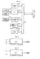
- FIG. 1 A preferred embodiment of an industrial control - system in accordance with the present invention is shown in FIG. 1 and, as shown therein, includes a plurality of remotely located device controllers R 1 , R 2 , R 3 ...R n-1 , R n each connected to one another through first and second communication links CL ⁇ and CL1.
- a combined-mode system supervisor S is also connected to communication links CL ⁇ and CL1 for the purpose, as described more fully below, of permitting convenient configuration or reconfiguration of the control architecture of the system and for the purpose of setting or alterating the operating parameters of the system.
- Each of the remotely located controller R n is connected to an associated input/output interface I/O 1 , I/O 2 , I/O 3 ,...I/O n-1 , and I/O n which, in turn, is connected to respective controlled devices and/or sensors CD/S 1 , CD/S 2 , CD/S 3 ...CD/S n-1 , and CD/S n .
- the system shown in FIG. 1 may be used for a wide variety of industrial process control applications including the exemplary application illustrated in FIG. 2 in which a flow of crushed fuel coal for a coal-fired steam generator (not shown) is controlled.
- the exemplary application includes a coal containing silo 10 that contains granulated coal and a feeder 12 located at the discharge port of the silo 10 for selectively controlling the rate of discharge of the coal from the silo 10 to a conveyor 14.
- the conveyed coal is delivered to the steam generator for subsequent combustion with the rate of flow measured by the belt scale 16.
- the system of FIG. 1 can be easily be configured to effect control of the coal flow by measuring the belt scale 16 output and comparing it with a predetermined high and/or low limits and controlling-the feeder 12 in response to the scale output.
- the control configuration of the system of FIG. 1 to achieve control of the exemplary application of FIG. 2 is accomplished through the combined mode system supervisor S, a detailed view of the architecture of which is shown in FIG . 3.
- the system supervisor S includes a supervisor buss 100 that interconnects the various devices that constitute the supervisor.
- These devices include a processor 102; an input device in the form of a keyboard 104a, connected to the buss 1 00 through an input/output device 104b; an EPROM programmer 104c also connected through the input/output device 104b; a magnetic storage device 106 a and an associated input/output and driver device 106b; an output device 108 which may include, for example, a video CRT screen 108 and printers 108b; and a memory 112 that serves the processor 102.
- the EPROM 11 contains instruction sets provided thereto by the EPROM programmer 104c through the input/output . device 104b. These instruction sets enable the system operator at the keyboard 104a, under the control of the processor 102, to effect the aforementioned changes in control system architecture and operating parameters.
- the magnetic media memory 106 provides temporary storage for operating data and--other parameters while the output devices 108a and 108b provide output information for the system operator in user- recognizable form.
- the instruction-sequence sets contained within the EPROM 112 provide two types of higher level user compatible control formats: instruction sets that develop block type symbolic representations for presentation to the system operator via the video output device 108a and alphanumeric type assembly language information also presented to the system operator on the video display 108a. Regardless of the mode of operation elected by the system operator, the operator, while at the keyboard 104a and viewing the video output device 108a can configure the system control architecture and establish the operating parameters.
- the instruction set for the first type of instructions is adapted to provide visual images of the functional blocks so that the system operator can manipulate the inputs and outputs of the blocks and interconnect them to provide a desired system architecture, such as an architecture for effecting control of the application shown in F I G. 2.
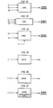
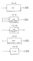
- FIGS. 4-24 The exemplary functional blocks developed by the instructions in the EPROM 104a for presentation and operation upon by the system controller are shown in FIGS. 4-24 with the function of each of these blocks described in the paragraphs below.
- This function symbol permits the system operator to obtain an output which is equal to the difference between a first and second input in which the second input is subtracted from the first input to form the output of the block as follows;
- This function symbol permits the system operator to select a block output that is a function of a proportional,an integral,and/or derivative function as follows:
- This function symbol permits the system operator to select, as the output, the lowest of two more inputs to the symbol as follows:
- This function symbol permits the system operator to select, as an output, the highest of two more inputs as follows:
- HIALM (FIG. 15)
- This functional symbol permits the system operator to generate an alarm output if the input exceeds a selected. value as follows:
- the function symbol permits the system operator to obtain an output that is.the product of the input and a fixed value as follows:
- RAMP Function designation: RAMP (FIG. 18)
- This function symbol permits the system operator to provide a block output that dynamically compensates an input signal by responding gradually to input signals, that is, lagging, and/or by anticipating the input signal, that is, leading the signal as follows:
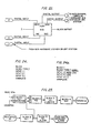
- the functional symbols described above permit the system operator to use the video output device 108a and the keyboard 104 (FIG. 3) to configure or reconfigure the operational architecture of the control system. This is accomplished when the operator, using the keyboard 104a, accesses the available function symbols by causing the function symbol interrogatories shown in FIG. 24 to be displayed.
- By assigning different types of block identifiers and inserting input identifiers it is possible to sequentially configure a control system arrangement as shown, for example, in FIG. 25 for effecting operation of the coal feeder arrangement of FIG. 2.
- the system operator calls up the logic and system parameter query display shown in FIG. 24. Thereafter, the system operator will develop the block functional diagram by designating the appropriate types of blocks and inputs thereof as follows:
- the system operator In setting up the first functional block of the crushed-coal feeder control (architecture shown in FIG. 25,) the system operator identifies the first block as block 1, specifies the so-identified block as a LOSEL (low input selector) block, specifies a first input as 1000 TPH (tons per hour), and specifies a second input as a counter input from a counter (not shown).
- the LOSEL block will select the lower of its two inputs. When the counter input is above 1000 TPH, the LOSEL block will always select the 1000 TPH value. On the other hand, when the counter input is below 1000 TPH, the LOSEL block will select the lower counter input. In this way, control of the crushed coal feed rate set point between zero and 1000 tons per hour can be readily achieved.
- the second functional block is established as follows: .
- the system operator identifies the block as block 2, specifies the so-identified block as a PID (proportional, integral, differential) functional block, specifies the first input (the set point SP input) as the output of block 1, specifies the second input (parameter variable PV) as the output of block 5 (discussed below).
- PID proportional, integral, differential
- the system operator In setting up the third block, the system operator identifies the block as a HULIM (high input limit) with the only input of the high limit block indicated as the output of block 2.
- the high limit block prevents flow rates greater than the preselected limit which limit is established as indicated in further detail below.
- the fourth block is configured as follows:
- the system operator identifies the block as block 4, specifies the so-identified block as an OUTSCAL block, and identifies its only input as the output of block 3.
- the OUTSCAL block scales the output of the high limit block and then provides its output to the feeder 12 (FIG, 2),
- the fifth block is established as follows:
- the system operator In setting-up the fifth functional block, the system operator identifies the block as block 5, specifies the block as an INSCAL block (input scaling), identifies the only input to the INSCAL block as the belt scale 16 output (FIG. 2). Block 5 thus scales the electrical output for use with the PID functional block, block 2.
- the sixth block is configured as follows:
- the system operator identifies the block as block 6, specifies that it is a HIALM block, (high alarm limit) and identifies its input as block 1.
- the output of the high alarm block 6 is directed to a conveyor belt overload enunciator.
- Additional functional control of the system of F IG . 2 may be achieved by an assembly language arrangement also accessible from the user system supervisor S.
- IF and IFO are used to interrogate the "ON” OR “OFF" status of an input device, output device, timer, or flag. If the status matches that of the instruction, the logic controller skips the instruction following the IF instruction and executes the next instruction. If the status does not match, the controller executes the instruction following the IF instruction:
- OUT is always used to turn an output device, timer or flag "ON” or “OFF” .
- OUT SKIP is the same as OUT but the controller skips the first-instruction following the OUT SKIP instruction and executes the second instruction.
- Jump causes the controller to resume operation at the specified statement number.
- GOTO is used to jump to a subroutine and causes the controller to store the number of the statement .following the GOTO instruction for use by GOBK instruction.
- GOBK is used at the end of a subroutine to resume execution at the statement number stored by the associated GOTO instruction.
- GOBK+ is used at the end of a subroutine to resume execution at the statement number stored by associated GOTO instruction plus the specified displacement number.
- TST is used to test the "ON” or "OFF” status of a designated input device, output device, timer or flag.
- the result of the TEST is used to set the conditions for the and and/or instructions.
- AND is used to test the "ON” or "OFF” status of the 'AND' condition.
- the "AND' condition is considered to be “ON” if the results of all the immediately preceding TST instructions were true. If the status matches that of the instruction, the logic controller skips the instruction following the TST instruction and executes the next instruction. If the status does not match, the controller executes the instruction following the AND instruction.
- OR is used to test the "ON” or "OFF” status of the 'OR' condition.
- the 'OR' condition is considered to be "ON” if the result of at least one of the immediately preceding TST instructions was true.
- Skip conditions are the same as AND.
- PLS is used to pulse an output device "ON" for a short period of time.
- the pulse period is adjustable from 200 MSEC to. 1.5 seconds.
- PLS SKIP is the same as PLS but the controller skips the instruction following PLS SKIP Emtruction.
- FLS is used to flash an output "ON” and "OFF" at the rate of 1 cycle a second.
- FLS SKIP is the same as FLS but the controller skips the instrction following the FLS SKIP instruction.
- MSG is used to print stored messages (identified by designated number) on a teletype, printer, or CRT.
- INC is used to increment the specfied counter by one.
- COMP tests the specified counter for greater than, equal to, or less than the specified number or counter.
- the skip conditions are the same as for the IF instructions.
- FIG. 26 an exemplary control flow diagram for control thereover is shown in FIG. 26 and may be readily implemented using the control instructions set fourth above.
- various decision blocks are provided by the IF-type control instruction to establish pre-start logic for the conveyor 14 including an IF query for the conveyor pull cord (not shown) status and a IF query for the conveyor belt alignment as well as other queries relating to the status of a 'run output' register, the start and stop push buttons, a conveyor speed transducer,and a delay timer.
- execution blocks shown in the lower part of FIG. 26 are provided to set or reset various registers and/or timers and provide an appropriate message on the video output device 108a which preferably takes the form of a CRT screen.
- a partial instruction listing that demonstrates the effecting of the flow diagram of FIG. 26 is provided below, a full listing not being necessary to provide an understanding of the exemplary instruction set.
- the instruction listings are typically constructed by the system operator using the keyboard 104a and the video display unit lOSa (FIG.3) by entering the control function instruction desired and providing appropriate device 'tags' or identifiers (e.g. PC50AA).
- Changes to the listing are accomplished by calling up the to-be-changed listing by either statement number or by label number. Thereafter a cursor displayed on the. video output unit 108a is moved by appropriate entry at the keyboard 104a over the area to be changed and the new information overtyped using the appropriate keys to effect the desired change.
- a system operator while using the keyboard 104a or the system supervisor and interacting with the video output device 108a can select a graphically displayed symbolic control function operator (as in FIGS.4-23) and/or the instruction set functional operators listed above for constructing control architectures for a control system.
Landscapes
- Engineering & Computer Science (AREA)
- Human Computer Interaction (AREA)
- Manufacturing & Machinery (AREA)
- Physics & Mathematics (AREA)
- General Physics & Mathematics (AREA)
- Automation & Control Theory (AREA)
- Control By Computers (AREA)
- Testing And Monitoring For Control Systems (AREA)
- Programmable Controllers (AREA)
- Feedback Control In General (AREA)
Applications Claiming Priority (2)
| Application Number | Priority Date | Filing Date | Title |
|---|---|---|---|
| US06/253,964 US4443861A (en) | 1981-04-13 | 1981-04-13 | Combined mode supervisory program-panel controller method and apparatus for a process control system |
| US253964 | 1994-06-03 |
Publications (2)
| Publication Number | Publication Date |
|---|---|
| EP0063045A2 true EP0063045A2 (de) | 1982-10-20 |
| EP0063045A3 EP0063045A3 (de) | 1984-09-05 |
Family
ID=22962385
Family Applications (1)
| Application Number | Title | Priority Date | Filing Date |
|---|---|---|---|
| EP82301890A Ceased EP0063045A3 (de) | 1981-04-13 | 1982-04-08 | Überwachungsverfahren in kombinierter Weise mittels einer Programmtafel-Steuerung für ein industrielles Prozess-Steuerungssystem |
Country Status (7)
| Country | Link |
|---|---|
| US (1) | US4443861A (de) |
| EP (1) | EP0063045A3 (de) |
| JP (1) | JPS57178503A (de) |
| AU (1) | AU549058B2 (de) |
| CA (1) | CA1184996A (de) |
| ES (1) | ES511285A0 (de) |
| MX (1) | MX153497A (de) |
Cited By (3)
| Publication number | Priority date | Publication date | Assignee | Title |
|---|---|---|---|---|
| GB2163927A (en) * | 1984-08-31 | 1986-03-05 | Gen Electric | Graphic display for a numerical control system |
| EP0184422A3 (en) * | 1984-12-03 | 1988-09-21 | Westinghouse Electric Corporation | Universal process control device and method |
| WO1997021155A1 (de) * | 1995-12-04 | 1997-06-12 | Dr. Johannes Heidenhain Gmbh | Verfahren zur steuerung einer mehrachsigen werkzeugmaschine |
Families Citing this family (50)
| Publication number | Priority date | Publication date | Assignee | Title |
|---|---|---|---|---|
| US4570217A (en) * | 1982-03-29 | 1986-02-11 | Allen Bruce S | Man machine interface |
| US4604690A (en) * | 1983-02-22 | 1986-08-05 | International Business Machines Corp. | Dynamic configuration for added devices |
| US4788657A (en) * | 1983-12-27 | 1988-11-29 | American Telephone And Telegraph Company | Communication system having reconfigurable data terminals |
| CA1253912A (en) * | 1984-11-08 | 1989-05-09 | Masao Hosaka | System for controlling image formation |
| US4641236A (en) * | 1985-05-06 | 1987-02-03 | The Boeing Company | Programmable machine tool control system |
| US4658348A (en) * | 1985-08-12 | 1987-04-14 | The Foxboro Company | Method and apparatus for configuring a controller |
| US4704676A (en) * | 1986-03-24 | 1987-11-03 | The Foxboro Company | Method and apparatus for configuring a controller |
| US5155836A (en) * | 1987-01-27 | 1992-10-13 | Jordan Dale A | Block diagram system and method for controlling electronic instruments with simulated graphic display |
| JPS6440640A (en) * | 1987-08-05 | 1989-02-10 | Ichikawa Woolen Textile | Control and monitor apparatus of loom |
| US4888714A (en) * | 1987-09-25 | 1989-12-19 | Laser Precision Corporation | Spectrometer system having interconnected computers at multiple optical heads |
| JPH0650457B2 (ja) * | 1987-10-14 | 1994-06-29 | シャープ株式会社 | コンピュータシステムのデバイス電源制御装置 |
| US4862345A (en) * | 1987-11-16 | 1989-08-29 | Litwin Engineers & Constructors, Inc. | Process plant instrumentation design system |
| US5088058A (en) * | 1988-08-26 | 1992-02-11 | Unisys Corporation | Apparatus and method for evaluating and predicting computer I/O performance using I/O workload snapshots for model input |
| US5270931A (en) * | 1989-02-23 | 1993-12-14 | The Boeing Company | Software controlled aircraft component configuration system |
| EP0449530A3 (en) * | 1990-03-23 | 1993-09-01 | Canon Kabushiki Kaisha | A memory medium having a control program memorized therein and an information processing method and an information processing apparatus using the same medium |
| JP2845606B2 (ja) * | 1990-10-31 | 1999-01-13 | 株式会社東芝 | 発電プラント制御装置 |
| US5276900A (en) * | 1990-12-14 | 1994-01-04 | Stream Computers | Master connected to common bus providing synchronous, contiguous time periods having an instruction followed by data from different time period not immediately contiguous thereto |
| US5297257A (en) * | 1991-04-15 | 1994-03-22 | Allen-Bradley Company, Inc. | Distributing a real-time control program to a plurality of input/output nodes |
| US5428769A (en) * | 1992-03-31 | 1995-06-27 | The Dow Chemical Company | Process control interface system having triply redundant remote field units |
| US5594858A (en) * | 1993-07-29 | 1997-01-14 | Fisher-Rosemount Systems, Inc. | Uniform control template generating system and method for process control programming |
| US5452201A (en) * | 1993-08-24 | 1995-09-19 | Allen-Bradley Company, Inc. | Industrial controller with highly distributed processing |
| US6182106B1 (en) * | 1993-08-30 | 2001-01-30 | International Business Machines Corporation | Method and system for providing a common hardware system console interface in data processing systems |
| US5576946A (en) * | 1993-09-30 | 1996-11-19 | Fluid Air, Inc. | Icon based process design and control system |
| JP3116710B2 (ja) * | 1994-03-18 | 2000-12-11 | 株式会社日立製作所 | 情報端末システム |
| US6094600A (en) * | 1996-02-06 | 2000-07-25 | Fisher-Rosemount Systems, Inc. | System and method for managing a transaction database of records of changes to field device configurations |
| US6868538B1 (en) * | 1996-04-12 | 2005-03-15 | Fisher-Rosemount Systems, Inc. | Object-oriented programmable controller |
| US5838563A (en) * | 1996-04-12 | 1998-11-17 | Fisher-Rosemont Systems, Inc. | System for configuring a process control environment |
| US5940294A (en) * | 1996-04-12 | 1999-08-17 | Fisher-Rosemont Systems, Inc. | System for assisting configuring a process control environment |
| EP0825506B1 (de) | 1996-08-20 | 2013-03-06 | Invensys Systems, Inc. | Verfahren und Gerät zur Fernprozesssteuerung |
| JP3489962B2 (ja) * | 1997-04-23 | 2004-01-26 | 沖電気工業株式会社 | プログラム開発装置および並列リアルタイム処理装置 |
| AU5025600A (en) | 1999-05-17 | 2000-12-05 | Foxboro Company, The | Process control configuration system with parameterized objects |
| US7096465B1 (en) | 1999-05-17 | 2006-08-22 | Invensys Systems, Inc. | Process control configuration system with parameterized objects |
| US7089530B1 (en) * | 1999-05-17 | 2006-08-08 | Invensys Systems, Inc. | Process control configuration system with connection validation and configuration |
| US7272815B1 (en) | 1999-05-17 | 2007-09-18 | Invensys Systems, Inc. | Methods and apparatus for control configuration with versioning, security, composite blocks, edit selection, object swapping, formulaic values and other aspects |
| US6754885B1 (en) | 1999-05-17 | 2004-06-22 | Invensys Systems, Inc. | Methods and apparatus for controlling object appearance in a process control configuration system |
| US6788980B1 (en) | 1999-06-11 | 2004-09-07 | Invensys Systems, Inc. | Methods and apparatus for control using control devices that provide a virtual machine environment and that communicate via an IP network |
| US6618630B1 (en) | 1999-07-08 | 2003-09-09 | Fisher-Rosemount Systems, Inc. | User interface that integrates a process control configuration system and a field device management system |
| AU6615600A (en) | 1999-07-29 | 2001-02-19 | Foxboro Company, The | Methods and apparatus for object-based process control |
| US6813523B2 (en) * | 2001-08-23 | 2004-11-02 | George Mauro | Distributed process control |
| EP1502218A4 (de) * | 2002-04-15 | 2005-08-17 | Invensys Sys Inc | Verfahren und vorrichtungen für ein auf prozess-, fabrikhallen-, umgebungs- und computer aided manufacturing basierendes oder anderweitiges steuersystem mit echtzeitdatenverteilung |
| US6839660B2 (en) * | 2002-04-22 | 2005-01-04 | Csi Technology, Inc. | On-line rotating equipment monitoring device |
| US20040076273A1 (en) * | 2002-10-18 | 2004-04-22 | Oman Paul W. | Text-to-voice system for communicating operational information from a protective device for a power system to a human user |
| US7761923B2 (en) | 2004-03-01 | 2010-07-20 | Invensys Systems, Inc. | Process control methods and apparatus for intrusion detection, protection and network hardening |
| US7444197B2 (en) * | 2004-05-06 | 2008-10-28 | Smp Logic Systems Llc | Methods, systems, and software program for validation and monitoring of pharmaceutical manufacturing processes |
| US7799273B2 (en) | 2004-05-06 | 2010-09-21 | Smp Logic Systems Llc | Manufacturing execution system for validation, quality and risk assessment and monitoring of pharmaceutical manufacturing processes |
| US7299102B2 (en) * | 2004-12-02 | 2007-11-20 | Norman Ken Ouchi | Method and system for engineering change implementation |
| WO2007123753A2 (en) | 2006-03-30 | 2007-11-01 | Invensys Systems, Inc. | Digital data processing apparatus and methods for improving plant performance |
| CN104407518B (zh) | 2008-06-20 | 2017-05-31 | 因文西斯系统公司 | 对用于过程控制的实际和仿真设施进行交互的系统和方法 |
| US8127060B2 (en) | 2009-05-29 | 2012-02-28 | Invensys Systems, Inc | Methods and apparatus for control configuration with control objects that are fieldbus protocol-aware |
| US8463964B2 (en) | 2009-05-29 | 2013-06-11 | Invensys Systems, Inc. | Methods and apparatus for control configuration with enhanced change-tracking |
Family Cites Families (7)
| Publication number | Priority date | Publication date | Assignee | Title |
|---|---|---|---|---|
| US3699529A (en) * | 1971-01-07 | 1972-10-17 | Rca Corp | Communication among computers |
| US3975622A (en) * | 1974-04-26 | 1976-08-17 | Forney Engineering Company | Programmable logic controller system |
| US3971000A (en) * | 1974-06-20 | 1976-07-20 | The Foxboro Company | Computer-directed process control system with interactive display functions |
| US4064394A (en) * | 1975-05-28 | 1977-12-20 | American Chain & Cable Company, Inc. | Electronic digital process controller having simulated analog control functions |
| US4303973A (en) * | 1976-10-29 | 1981-12-01 | The Foxboro Company | Industrial process control system |
| JPS55143607A (en) * | 1979-04-26 | 1980-11-10 | Mitsubishi Electric Corp | Process controller |
| JPS5624606A (en) * | 1979-08-07 | 1981-03-09 | Toshiba Corp | Programmable controller |
-
1981
- 1981-04-13 US US06/253,964 patent/US4443861A/en not_active Expired - Lifetime
-
1982
- 1982-02-03 AU AU80146/82A patent/AU549058B2/en not_active Ceased
- 1982-03-23 CA CA000399203A patent/CA1184996A/en not_active Expired
- 1982-03-24 MX MX191960A patent/MX153497A/es unknown
- 1982-04-02 JP JP57053948A patent/JPS57178503A/ja active Pending
- 1982-04-07 ES ES511285A patent/ES511285A0/es active Granted
- 1982-04-08 EP EP82301890A patent/EP0063045A3/de not_active Ceased
Non-Patent Citations (1)
| Title |
|---|
| ADVANCES IN INSTRUMENTATION, vol. 30, no. 4, 1975, pages 808-1 - 808-8, Pittsburg, US * |
Cited By (4)
| Publication number | Priority date | Publication date | Assignee | Title |
|---|---|---|---|---|
| GB2163927A (en) * | 1984-08-31 | 1986-03-05 | Gen Electric | Graphic display for a numerical control system |
| EP0184422A3 (en) * | 1984-12-03 | 1988-09-21 | Westinghouse Electric Corporation | Universal process control device and method |
| WO1997021155A1 (de) * | 1995-12-04 | 1997-06-12 | Dr. Johannes Heidenhain Gmbh | Verfahren zur steuerung einer mehrachsigen werkzeugmaschine |
| US6249102B1 (en) | 1995-12-04 | 2001-06-19 | Dr. Johannes Heidenhain Gmbh | Method of controlling a multi-axis machine tool |
Also Published As
| Publication number | Publication date |
|---|---|
| EP0063045A3 (de) | 1984-09-05 |
| MX153497A (es) | 1986-11-07 |
| CA1184996A (en) | 1985-04-02 |
| US4443861A (en) | 1984-04-17 |
| ES8307388A1 (es) | 1983-07-01 |
| ES511285A0 (es) | 1983-07-01 |
| AU8014682A (en) | 1982-10-21 |
| AU549058B2 (en) | 1986-01-09 |
| JPS57178503A (en) | 1982-11-02 |
Similar Documents
| Publication | Publication Date | Title |
|---|---|---|
| EP0063045A2 (de) | Überwachungsverfahren in kombinierter Weise mittels einer Programmtafel-Steuerung für ein industrielles Prozess-Steuerungssystem | |
| US5644487A (en) | Monitoring and control system and method | |
| US5321829A (en) | Graphical interfaces for monitoring ladder logic programs | |
| US5576946A (en) | Icon based process design and control system | |
| US6629003B1 (en) | Batch processing control system recipe management and batch information system | |
| US4991076A (en) | Method and apparatus for creating custom displays for monitoring ladder logic programs | |
| CA1057405A (en) | Electronic digital process controller having simulated analog control functions | |
| EP0043201A1 (de) | Steuerungssystem für industriellen Prozess | |
| US20060178760A1 (en) | Configurable interface configuration method and system using a remote interface | |
| EP0416512A2 (de) | Programmierbare Überwachungseinrichtung und Verfahren | |
| US7620459B2 (en) | Controlling and operating technical processes | |
| US5237652A (en) | Programming system for programmable logic controller | |
| US6760630B2 (en) | Method and implementation of process control | |
| US6334075B1 (en) | Data processor providing interactive user configuration of data acquisition device storage format | |
| GB2295466A (en) | Production line simulator | |
| US5963446A (en) | Extended relay ladder logic for programmable logic controllers | |
| US4885575A (en) | Method and means of displaying information | |
| EP0362392A1 (de) | Rechnersimulierungssystem | |
| EP0252171A1 (de) | Steuersystem für Kraftwerküberwachung | |
| US5463544A (en) | Programmable controller and method of monitoring a sequence program thereof | |
| Fowler et al. | Development of real time expert system applications for the on-line analysis of fermentation respiration data | |
| JP3167245B2 (ja) | プログラマブルコントローラ動作状態監視装置 | |
| EP0120287A1 (de) | Operatorschnittstellensystem und -verfahren | |
| JPH036704A (ja) | 分散型制御システム | |
| JPS61148324A (ja) | プロセス表示装置 |
Legal Events
| Date | Code | Title | Description |
|---|---|---|---|
| PUAI | Public reference made under article 153(3) epc to a published international application that has entered the european phase |
Free format text: ORIGINAL CODE: 0009012 |
|
| AK | Designated contracting states |
Designated state(s): CH DE FR GB IT NL |
|
| 17P | Request for examination filed |
Effective date: 19830114 |
|
| PUAL | Search report despatched |
Free format text: ORIGINAL CODE: 0009013 |
|
| AK | Designated contracting states |
Designated state(s): CH DE FR GB IT LI NL |
|
| STAA | Information on the status of an ep patent application or granted ep patent |
Free format text: STATUS: THE APPLICATION HAS BEEN REFUSED |
|
| 18R | Application refused |
Effective date: 19880610 |
|
| APAF | Appeal reference modified |
Free format text: ORIGINAL CODE: EPIDOSCREFNE |
|
| RIN1 | Information on inventor provided before grant (corrected) |
Inventor name: SLATER, BILLY R. |