EP0062589A1 - Door check - Google Patents
Door check Download PDFInfo
- Publication number
- EP0062589A1 EP0062589A1 EP82400627A EP82400627A EP0062589A1 EP 0062589 A1 EP0062589 A1 EP 0062589A1 EP 82400627 A EP82400627 A EP 82400627A EP 82400627 A EP82400627 A EP 82400627A EP 0062589 A1 EP0062589 A1 EP 0062589A1
- Authority
- EP
- European Patent Office
- Prior art keywords
- rod
- door
- base
- bearing surface
- horn
- Prior art date
- Legal status (The legal status is an assumption and is not a legal conclusion. Google has not performed a legal analysis and makes no representation as to the accuracy of the status listed.)
- Granted
Links
Images


Classifications
-
- E—FIXED CONSTRUCTIONS
- E05—LOCKS; KEYS; WINDOW OR DOOR FITTINGS; SAFES
- E05B—LOCKS; ACCESSORIES THEREFOR; HANDCUFFS
- E05B65/00—Locks or fastenings for special use
- E05B65/0014—Locks or fastenings for special use to prevent opening by children
-
- E—FIXED CONSTRUCTIONS
- E05—LOCKS; KEYS; WINDOW OR DOOR FITTINGS; SAFES
- E05C—BOLTS OR FASTENING DEVICES FOR WINGS, SPECIALLY FOR DOORS OR WINDOWS
- E05C17/00—Devices for holding wings open; Devices for limiting opening of wings or for holding wings open by a movable member extending between frame and wing; Braking devices, stops or buffers, combined therewith
- E05C17/02—Devices for holding wings open; Devices for limiting opening of wings or for holding wings open by a movable member extending between frame and wing; Braking devices, stops or buffers, combined therewith by mechanical means
- E05C17/04—Devices for holding wings open; Devices for limiting opening of wings or for holding wings open by a movable member extending between frame and wing; Braking devices, stops or buffers, combined therewith by mechanical means with a movable bar or equivalent member extending between frame and wing
-
- Y—GENERAL TAGGING OF NEW TECHNOLOGICAL DEVELOPMENTS; GENERAL TAGGING OF CROSS-SECTIONAL TECHNOLOGIES SPANNING OVER SEVERAL SECTIONS OF THE IPC; TECHNICAL SUBJECTS COVERED BY FORMER USPC CROSS-REFERENCE ART COLLECTIONS [XRACs] AND DIGESTS
- Y10—TECHNICAL SUBJECTS COVERED BY FORMER USPC
- Y10S—TECHNICAL SUBJECTS COVERED BY FORMER USPC CROSS-REFERENCE ART COLLECTIONS [XRACs] AND DIGESTS
- Y10S292/00—Closure fasteners
- Y10S292/38—Plastic latch parts
-
- Y—GENERAL TAGGING OF NEW TECHNOLOGICAL DEVELOPMENTS; GENERAL TAGGING OF CROSS-SECTIONAL TECHNOLOGIES SPANNING OVER SEVERAL SECTIONS OF THE IPC; TECHNICAL SUBJECTS COVERED BY FORMER USPC CROSS-REFERENCE ART COLLECTIONS [XRACs] AND DIGESTS
- Y10—TECHNICAL SUBJECTS COVERED BY FORMER USPC
- Y10T—TECHNICAL SUBJECTS COVERED BY FORMER US CLASSIFICATION
- Y10T292/00—Closure fasteners
- Y10T292/08—Bolts
- Y10T292/0894—Spring arm
- Y10T292/0907—Multiple head
Definitions
- the present invention relates to apparatus or devices limiting the opening stroke for door leaves.
- the device according to the invention makes it possible to satisfy these conditions by mounting two pieces which hang one inside the other, one being fixed on the frame and the other on the leaf of the door.
- one of the two parts must be deformable and the other rigid.
- the rigid part 1, Figs. 1, 2 and 3 consists of a substantially parallelepiped base 17 with a face 18 which is applied to the face of the door frame by means of screws passing through oblong holes 19, with on an edge, not adjacent to the face 18, a protrusion in the form of two yokes or horns 3 and 4, defining, between them, a common housing or seat 2 for receiving the end of a flexible piece.
- the horns 3 and 4 have their ends in the form of dihedrons whose edges are parallel to the edge of the base on which they are placed.
- the general orientations of the horns 3 and 4 make, by way of example, angles of 30 ° or 60 ° relative to the plane of the surface 18.
- the bottom of the bearing surface 2 is cylindrical parallel to the edge of the base carrying the horns 3 and 4, the axis of the cylinder being indicated at 20.
- the face of the base opposite the horns 3 and 4 and which is perpendicular to the face 18 bears the reference 7.
- the horns 3 and 4 are, in the transverse direction, separated into two parts by a groove - 8, 9, the bottom of which coincides, on the one hand, with the face 21 of the base opposite to 18 and the face 10 of the opposite base to 7.
- the rigid part 22 also consists of a substantially parallelepiped base- that 23 with a face 24 which is applied to the face of the frame of a door by means of screws passing through oblong holes 25, with on a ridge, not adjacent to the face 24, a horn-shaped projection 26 oriented substantially at 45 ° relative to the face 24.
- the end of the horn 26 has the shape of a dihedron whose edge is parallel to the edge of the base which carries it.
- the faces 27 and 28 of the dihedral change slope, at a certain distance from the end of the horn, to form concave bearing surfaces 2bis and 2ter.
- the faces 27 and 28 slide the cylinder 11 from the other part towards the housing or upper seat 2bis or the housing or lower seat 2ter.
- the horn 26 is divided transversely into two symmetrical parts by a groove 29, one bottom of which coincides with one face of the base 22 and the other with another face, these two faces defining the edge on which the horn 26 is placed.
- a flexible blade provides the connection between the rod 12 and the base 16.
- a spring provides the connection between the rod 12 and the base 16.
- Figs. 9a, 9b has a groove 29 for receiving the rod 12 in two mounting positions and differs mainly from the first embodiment in that it comprises two seats 2bis and 2ter with a horn 26, separated in two by 29.
- the base of FigÉ. 9a, 9b can be mounted like the base 1 with respect to the flexible part 11, 12, 16.
- the rod 12 is perpendicular to the face 24 of the base 23 of the part 22 and passes through the groove 29 in the middle of the horn 26, the tenon 11 coming to bear in the seat 2bis.
- the rod 12 is parallel to the face 24 of the base 23 of the part 22 and passes through the groove 29 in the middle of the horn 26, the tenon 11 being in abutment on the surface 2ter.
- a bracket 30 is provided, itself mounted on the opening by means of a shim 31 Screws 32 and 33 secure these parts.
- oblong fixing holes allow adjustment of the position of the parts with respect to their supports or between them.
- the device, object of the invention can be used on each existing door in a dwelling, whenever this represents a danger for the child for its movement, for example, cupboard containing crockery or dangerous products, door of communication giving on a staircase or a workshop.
Abstract
Description
La présente invention concerne des appareils ou dispositifs limiteurs de course d'ouverture pour battants de portes.The present invention relates to apparatus or devices limiting the opening stroke for door leaves.
Les dispositifs connus avec tringle, chaîne, ajourage oblong, et montés comme sécurité aux portes d'entrée des habitations, ne permettent pas de satisfaire toutes les conditions du problème suivant:
- un enfant en bas âge ouvre toutes les portes dans une habitation ce qui représente un désagrément pour les parents qui doivent le surveiller constamment afin d'éviter un accident.
- a toddler opens all the doors in a home, which represents an inconvenience for parents who must constantly watch him to avoid an accident.
Les conditions à remplir sont donc les suivantes:
- a) que le dispositif s'accroche automatiquement dès la fermeture de la porte pour éviter les oublis,
- b) que le dispositif soit utilisable aussi bien sur les portes battantes que sur les portes coulissantes,
- c) que le décrochage pour l'ouverture soit très difficile ou impossible pour l'enfant,
- d) que, dans le cas d'une porte de communication (escalier, cave, atelier, ...), le décrochage puisse se faire des deux côtés de celle-ci.
- a) that the device hooks automatically as soon as the door is closed to avoid oversights,
- b) that the device can be used both on hinged doors and on sliding doors,
- c) that dropping out for the opening is very difficult or impossible for the child,
- d) that, in the case of a communication door (staircase, cellar, workshop, ...), the stall can be done on both sides of it.
Dans le domaine intéressant le dispositif suivant l'invention, l'état de la technique peut être illustré par les brevets US 3 889 992 et 3 397 001. Toutefois, les limiteurs de course de battants de portes ou de tiroirs décrits dans ces brevets ne remplissent pas toutes conditions à remplir énoncées ci-dessus.In the field of interest of the device according to the invention, the state of the art can be illustrated by US patents 3,889,992 and 3,397,001. However, the stroke limiters for door or drawer wings described in these patents do not not meet all of the above conditions.
Par contre, le dispositif selon l'invention permet de satisfaire à ces conditions par le montage de deux pièces venant s'accrocher l'une dans l'autre, l'une, étant fixée sur le dormant et l'autre sur le battant de la porte. Pour que l'accrochage automatique et le décrochage volontaire soient possibles, l'une des deux pièces doit être déformable et l'autre rigide.On the other hand, the device according to the invention makes it possible to satisfy these conditions by mounting two pieces which hang one inside the other, one being fixed on the frame and the other on the leaf of the door. For automatic attachment and voluntary removal to be possible, one of the two parts must be deformable and the other rigid.
Les caractéristiques de l'invention mentionnées ci-dessus, ainsi que d'autres, apparaîtront plus clairement à la lecture de la description d'exemples de réalisation, ladite description étant faite en relation avec les dessins joints, parmi lesquels:
- les Figs. 1 à 3 sont trois vues différentes de la pièce rigide d'un exemple de réalisation d'un appareil suivant l'invention,
- - la Fig. 1 étant une coupe de la Fig. 3 suivant la ligne A-A,
- - la Fig. 2 étant une vue en élévation arrière,
- - la Fig. 3 étant une vue en plan,
- les Figs. 4 et 5 sont respectivement des vues en élévation et en plan de la pièce déformable coopérant avec la pièce des Figs. 1 à 3,
- la Fig. 6 est une vue en élévation, avec coupe partielle illustrant une forme de montage de l'appareil,
- la Fig. 7 est une vue en élévation, avec coupe partielle, d'une autre forme de montage de l'appareil,
- la Fig. 8 est encore une vue en élévation, avec coupe partielle, d'une autre forme de montage de l'appareil,
- la Fig. 9a est une vue en élévation, avec coupe, d'un second exemple de réalisation de la partie rigide de l'appareil,
- la Fig. 9b est une vue en plan de la pièce montrée à la Fig. 9a, et
- les Figs. 10 et 11 illustrent deux formes de montage du dispositif de la Fig. 9.
- Figs. 1 to 3 are three different views of the rigid part of an embodiment of an apparatus according to the invention,
- - Fig. 1 being a section of FIG. 3 along line AA,
- - Fig. 2 being a rear elevation view,
- - Fig. 3 being a plan view,
- Figs. 4 and 5 are respectively views in elevation and in plan of the deformable part cooperating with the part of FIGS. 1 to 3,
- Fig. 6 is an elevational view, with partial section illustrating a form of mounting of the device,
- Fig. 7 is an elevational view, partly in section, of another form of mounting of the device,
- Fig. 8 is still an elevational view, with partial section, of another form of mounting of the apparatus,
- Fig. 9a is an elevational view, in section, of a second embodiment of the rigid part of the apparatus,
- Fig. 9b is a plan view of the part shown in FIG. 9a, and
- Figs. 10 and 11 illustrate two forms of mounting the device of FIG. 9.
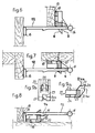
Dans le premier exemple de réalisation, la pièce rigide 1, Figs. 1, 2 et 3, se compose d'une embase sensiblement parallèlépipèdi- que 17 avec une face 18 qui s'applique sur la face du dormant de la porte au moyen de vis passant à travers des trous oblongs 19, avec sur une arête, non adjacente à la face 18, une excroissance en forme de deux chapes ou cornes 3 et 4, définissant, entre elles, un logement ou siège commun 2 pour la réception du bout d'une pièce flexible. Les cornes 3 et 4 ont leurs bouts en forme de dièdres dont les arêtes sont parallèles à l'arête de l'embase sur laquelle elles sont placées. Les orientations générales des cornes 3 et 4 font, à titre d'exemple, des angles de 30° ou de 60° par rapport au plan de la surface 18. Le fond de la surface d'appui 2 est cylindrique parallèle à l'arête de l'embase portant les cornes 3 et 4, l'axe du cylindre étant indiqué en 20. La face de l'embase opposée aux cornes 3 et 4 et qui est perpendiculaire à la face 18 porte la référence 7. Les cornes 3 et 4 sont, dans le sens transversal, séparées en deux parties par une rainure- 8, 9, dont le fond coïncide, d'une part, avec la face 21 de l'embase opposée à 18 et la face 10 de l'embase opposée à 7.In the first embodiment, the
Dans le deuxième-exemple de réalisation, Figs. 9a, 9b, la pièce rigide 22 se compose aussi d'une embase sensiblement parallélépipèdi- que 23 avec une face 24 qui s'applique sur la face du dormant d'une porte au moyen de vis passant à travers des trous oblongs 25, avec sur une arête, non adjacente à la face 24, un excroissance en forme de corne 26 orientée sensiblement à 45° par rapport à la face 24. Le bout de la corne 26 a la forme d'un dièdre dont l'arête est parallèle à l'arête de l'embase qui la porte. Les faces 27 et 28 du dièdre changent de pente, à une certaine distance du bout de la corne, pour former des surfaces d'appui concaves 2bis et 2ter. En pratique, les faces 27 et 28 font glisser le cylindre 11 de l'autre pièce vers le logement ou siège supérieur 2bis ou le logement ou siège inférieur 2ter. La corne 26 est divisée transversalement en deux partie symétriques par une rainure 29 dont un fond coïncide avec une face de l'embase 22 et l'autre avec une autre face, ces deux faces définissant l'arête sur laquelle est placée la corne 26.In the second embodiment, Figs. 9a, 9b, the
La pièce flexible ou déformable, Figs. 4 et 5, est formée d'une tige 12, à une extrémité de laquelle est prévue une partie plus grosse 11, destinée à venir prendre place dans le logement 2 (ou les logements 2bis et 2ter), et à son autre extrémité une base 16. La partie plus grosse 11 a la forme d'un tenon cylindrique, perpendiculaire à la tige 12 et formant un T avec celle-ci. La base 16 est perpendiculaire à la tige 12. La tige 12 est en matière relativement flexible et élastique, de manière à pouvoir l'incliner par rapport à la base 16. Dans la zone médiane de la tige 12, est prévue une excroissance en forme de dent de scie, avec une face oblique 15, du côté tenon 11, et une face 14 perpendiculaire à 12, du côté base 16.The flexible or deformable part, Figs. 4 and 5, is formed by a
Dans un autre exemple de réalisation, non montré, une lame souple assure la liaison entre la tige 12 et la base 16.In another exemplary embodiment, not shown, a flexible blade provides the connection between the
Dans un autre exemple de réalisation, non montré, un ressort assure la liaison entre la tige 12 et la base 16.In another exemplary embodiment, not shown, a spring provides the connection between the
Dans l'exemple de réalisation montré, en utilisant l'élasticité des matériaux, le ressort et l'articulation, la lame souple ou le ressort sont supprimés.In the embodiment shown, using the elasticity of the materials, the spring and the joint, the flexible blade or the spring are eliminated.
La tige de liaison 12 de la pièce déformable a un triple rôle:
- 1) limiter la longueur de la course du battant,
- 2) recevoir la pression du doigt lorsque la porte est entre- baillée afin de procéder au décrochage des pièces,
- 3) se déformer lorsque la matière qui la constitue est très élastique.
- 1) limit the length of the leaf stroke,
- 2) receive pressure from the finger when the door is partially open in order to unhook the parts,
- 3) to deform when the material which constitutes it is very elastic.
Dans les Figs. 1 à 5, les deux pièces sont monoblocs et réalisées par injection d'une matière thermoplastique.In Figs. 1 to 5, the two parts are in one piece and produced by injection of a thermoplastic material.
Les Figs. 6 à 8 représentent différents exemples de positions d'accrochage des pièces entre elles, la base 16 et l'embase 17 étant montrées respectivement fixées sur un battant et un ouvrant:
- A la Fig. 6, la tige 12 est perpendiculaire à la
face 18 de l'embase 17 et passe dans la partie 9 de la rainure, au milieu de lacorne 3. - A la Fig. 7, la tige 12 est parallèle à la
face 18 de l'embase 17-et passe dans la partie 8 de la rainure, au milieu de lacorne 4. - A la Fig. 8, la tige 12 est encore parallèle à la
face 18 de l'embase 17 et passe encore au milieu de lacorne 4, mais ici ladent - A la Fig. 6, on voit qu'à la fermeture, le cylindre 11 vient glisser sur la
face externe 6 de lacorne 3 en déformant la tige 12 qui reprend sa forme originelle après passage grâce à la rainure 9. A l'ouverture le cylindre 11 vient buter sur la face interne de lacorne 3 qui le fait glisser vers le siège 2. - A la Fig. 7, on voit qu'à la fermeture, le cylindre 11 vient glisser sur la
face externe 5 de lacorne 4 en déformant la tige 12 qui reprend sa forme originelle après passage grâce à la rainure 8. A l'ouverture le cylindre 11 vient buter sur la face interne de lacorne 4 qui le fait glisser vers le siège 2. - A la Fig. 8, on voit qu'à la fermeture, le processus d'engagement du cylindre 11 est identique à celui de la Fig. 7, mais, de plus,
la dent 15 en venant sur le fond de la rainure 8 déforme la tige 12 jusqu'à ce que laface 7 de labase 1 vienne en contact avecla face 13 de labase 16 absorbant ainsi le choc à l'ouverture du battant. Pour le mouvement inverse,la face 14 de ladent 15 vient en contact avecla face 10 de labase 1 provoquant l'immobilisation des deux pièces. Si ce maintien, vient à lâcher, le cylindre 11 vient se loger dans 2 garantissant l'arrêt du mouvement.
- In Fig. 6, the
rod 12 is perpendicular to theface 18 of thebase 17 and passes through the part 9 of the groove, in the middle of thehorn 3. - In Fig. 7, the
rod 12 is parallel to theface 18 of thebase 17 and passes through thepart 8 of the groove, in the middle of thehorn 4. - In Fig. 8, the
rod 12 is still parallel to theface 18 of thebase 17 and still passes through the middle of thehorn 4, but here thetooth part 1. - In Fig. 6, we see that when closing, the
cylinder 11 comes to slide on theexternal face 6 of thehorn 3 by deforming therod 12 which resumes its original shape after passage thanks to the groove 9. At the opening thecylinder 11 comes abut on the internal face of thehorn 3 which slides it towards theseat 2. - In Fig. 7, it can be seen that on closing, the
cylinder 11 comes to slide on theexternal face 5 of thehorn 4 by deforming therod 12 which returns to its original shape after passage thanks to thegroove 8. At the opening thecylinder 11 comes abut on the internal face of thehorn 4 which slides it towards theseat 2. - In Fig. 8, it can be seen that on closing, the process of engaging the
cylinder 11 is identical to that of FIG. 7, but, moreover, thetooth 15 coming from the bottom of thegroove 8 deforms therod 12 until theface 7 of thebase 1 comes into contact with theface 13 of the base 16 thus absorbing the shock at the opening of the leaf. For the reverse movement, theface 14 of thetooth 15 comes into contact with theface 10 of thebase 1 causing the immobilization of the two parts. If this holding comes to drop, thecylinder 11 is housed in 2 ensuring the movement stops.
Il faut noter que l'exemple de réalisation des Figs. 9a, 9b a une rainure 29 pour recevoir la tige 12 suivant deux positions de montage et diffère principalement du premier exemple de réalisation en ce qu'elle comporte deux sièges 2bis et 2ter avec une corne 26, séparées en deux par 29. L'embase des FigÉ. 9a, 9b peut être montée comme la base 1 par rapport à la pièce flexible 11, 12, 16.It should be noted that the embodiment of Figs. 9a, 9b has a
A la Fig. 10, la tige 12 est perpendiculaire à la face 24 de l'embase 23 de la pièce 22 et passe dans la rainure 29 au milieu de la corne 26, le tenon 11 venant en appui dans le siège 2bis.In Fig. 10, the
A la Fig. 11, la tige 12 est parallèle à la face 24 de l'embase 23 de la pièce 22 et passe dans la rainure 29 au milieu de la corne 26, le tenon 11 étant en appui sur la surface 2ter.In Fig. 11, the
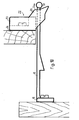
L'ouvrant et le battant étant parallèles, et l'ouvrant pouvant glisser vers le dormant, pour fixer la base 16, on a prévu une équerre 30, elle-même montée sur l'ouvrant au moyen d'une cale d'épaisseur 31. Des vis 32 et 33 assurent les fixations de ces pièces.The opening and the leaf being parallel, and the opening being able to slide towards the frame, to fix the
Sur les deux pièces, des trous oblongs de fixation permettent un réglage de la position des pièces par rapport à leurs supports ou entre elles.On the two parts, oblong fixing holes allow adjustment of the position of the parts with respect to their supports or between them.
Le décrochage peut se faire en déformant la tige 12 soit par action sur le cylindre 11 soit par action sur la partie de la tige 12 apparaissant à l'entrebaillement. Le sens des pentes 3 et 4 fait que le décrochage n'est possible que lorsque le battant n'est pas en ouverture maximale. La fixation du dispositif se faisant en plus, bien sûr, à une hauteur inaccessible pour l'enfant.The stall can be done by deforming the
Le dispositif, objet de l'invention, peut être utilisé sur chaque porte existante dans une habitation, chaque fois que celle-ci représente pour son déplacement un danger pour l'enfant, exemple, placard contenant de la vaisselle ou des produits dangereux, porte de communication donnant sur un escalier ou un atelier.The device, object of the invention, can be used on each existing door in a dwelling, whenever this represents a danger for the child for its movement, for example, cupboard containing crockery or dangerous products, door of communication giving on a staircase or a workshop.
Claims (13)
Priority Applications (1)
| Application Number | Priority Date | Filing Date | Title |
|---|---|---|---|
| AT82400627T ATE14471T1 (en) | 1981-04-07 | 1982-04-06 | OPENING RESTRICTOR FOR ONE DOOR. |
Applications Claiming Priority (2)
| Application Number | Priority Date | Filing Date | Title |
|---|---|---|---|
| FR8107312A FR2503229A1 (en) | 1981-04-07 | 1981-04-07 | RACE LIMITING DEVICE FOR DOOR DOOR |
| FR8107312 | 1981-07-04 |
Publications (2)
| Publication Number | Publication Date |
|---|---|
| EP0062589A1 true EP0062589A1 (en) | 1982-10-13 |
| EP0062589B1 EP0062589B1 (en) | 1985-07-24 |
Family
ID=9257293
Family Applications (1)
| Application Number | Title | Priority Date | Filing Date |
|---|---|---|---|
| EP82400627A Expired EP0062589B1 (en) | 1981-04-07 | 1982-04-06 | Door check |
Country Status (5)
| Country | Link |
|---|---|
| US (1) | US4432574A (en) |
| EP (1) | EP0062589B1 (en) |
| AT (1) | ATE14471T1 (en) |
| DE (1) | DE3264862D1 (en) |
| FR (1) | FR2503229A1 (en) |
Cited By (1)
| Publication number | Priority date | Publication date | Assignee | Title |
|---|---|---|---|---|
| FR2545140A1 (en) * | 1983-04-29 | 1984-11-02 | Varlet Marc | OPENING RUN LIMITER DEVICE |
Families Citing this family (2)
| Publication number | Priority date | Publication date | Assignee | Title |
|---|---|---|---|---|
| US4688836A (en) * | 1984-04-24 | 1987-08-25 | Varlet Marc F | Latch assembly |
| GB2298231B (en) * | 1995-02-24 | 1999-01-27 | Rozarieux David Michael De | Safety catch |
Citations (1)
| Publication number | Priority date | Publication date | Assignee | Title |
|---|---|---|---|---|
| US3889992A (en) * | 1973-11-23 | 1975-06-17 | Shur Lok Manufacturing Co Inc | Latch assembly |
Family Cites Families (5)
| Publication number | Priority date | Publication date | Assignee | Title |
|---|---|---|---|---|
| US906452A (en) * | 1908-05-04 | 1908-12-08 | Neil T Mccleer | Sliding-door fastener. |
| US1725419A (en) * | 1926-06-14 | 1929-08-20 | Mattice L Raymond | Storm-window fastener |
| US1872471A (en) * | 1929-05-18 | 1932-08-16 | Chrysler Corp | Fastening means |
| US1856569A (en) * | 1930-11-28 | 1932-05-03 | Arthur T Larsen | Storm sash fastener |
| US3397001A (en) * | 1966-09-28 | 1968-08-13 | Nathan R. Friedman | Closure latch assembly |
-
1981
- 1981-04-07 FR FR8107312A patent/FR2503229A1/en active Granted
-
1982
- 1982-03-30 US US06/363,418 patent/US4432574A/en not_active Expired - Lifetime
- 1982-04-06 EP EP82400627A patent/EP0062589B1/en not_active Expired
- 1982-04-06 DE DE8282400627T patent/DE3264862D1/en not_active Expired
- 1982-04-06 AT AT82400627T patent/ATE14471T1/en not_active IP Right Cessation
Patent Citations (1)
| Publication number | Priority date | Publication date | Assignee | Title |
|---|---|---|---|---|
| US3889992A (en) * | 1973-11-23 | 1975-06-17 | Shur Lok Manufacturing Co Inc | Latch assembly |
Cited By (2)
| Publication number | Priority date | Publication date | Assignee | Title |
|---|---|---|---|---|
| FR2545140A1 (en) * | 1983-04-29 | 1984-11-02 | Varlet Marc | OPENING RUN LIMITER DEVICE |
| EP0125197A1 (en) * | 1983-04-29 | 1984-11-14 | Marc France Varlet | Door opening checking device |
Also Published As
| Publication number | Publication date |
|---|---|
| FR2503229A1 (en) | 1982-10-08 |
| FR2503229B1 (en) | 1983-05-13 |
| EP0062589B1 (en) | 1985-07-24 |
| US4432574A (en) | 1984-02-21 |
| ATE14471T1 (en) | 1985-08-15 |
| DE3264862D1 (en) | 1985-08-29 |
Similar Documents
| Publication | Publication Date | Title |
|---|---|---|
| WO2008096251A1 (en) | Compact elastic hinge for spectacle frames | |
| CH703540B1 (en) | Folding clasp for bracelet and method of assembling such a clasp. | |
| EP0062589B1 (en) | Door check | |
| EP0125197A1 (en) | Door opening checking device | |
| FR2598996A2 (en) | Fastening and safety device for pedals of bicycles and similar vehicles | |
| FR2587880A1 (en) | Protective case for fishing articles | |
| FR2787498A1 (en) | Limited tilt window assembly for a vehicle such as train carriage, includes an integral safety unit to retain glass panel in place in the event of breakage | |
| EP0881347A1 (en) | Locking device for a sliding door or a sliding window, or similar | |
| FR2667347A1 (en) | Articulated supports for doors and windows | |
| FR2800759A1 (en) | Assisted unhinging mechanism for road barrier bar in event of vehicle impact | |
| WO2018202378A1 (en) | Clasp for jewellery item | |
| FR2901680A1 (en) | DEVICE FOR JOINING TWO TUBES CONSTITUTING A SEAT AND PROTECTING THE JOINT AREA THEREOF | |
| FR2728141A1 (en) | Cage for snaring animals | |
| EP0013228B1 (en) | Device for holding a window in an opened position | |
| EP1134341A1 (en) | Articulated door system for vehicles, containers and similar | |
| FR2672927A1 (en) | Safety clutch for a handle of doors or of windows | |
| FR2647354A1 (en) | Device for protecting extinguishers | |
| FR2627953A1 (en) | Trap for trapping small animals - has jaws which are covered with rubber or plastics to prevent mutilation of animal | |
| FR2766676A1 (en) | Hair grip with spring=loaded hinge | |
| FR2655369A1 (en) | System for facilitating the closure of fridge doors | |
| EP0859107A1 (en) | Fastening device for sliding objects | |
| BE518147A (en) | ||
| FR2633968A1 (en) | Automatic fastening and locking device for safety bars on closing elements of the shutter, blind, door and suchlike type | |
| FR2695810A1 (en) | Perfected case. | |
| FR2629510A1 (en) | Wind stop for leaves of shutters of doors, French doors (patio doors), windows or the like |
Legal Events
| Date | Code | Title | Description |
|---|---|---|---|
| PUAI | Public reference made under article 153(3) epc to a published international application that has entered the european phase |
Free format text: ORIGINAL CODE: 0009012 |
|
| AK | Designated contracting states |
Designated state(s): AT BE CH DE GB IT LU NL SE |
|
| 17P | Request for examination filed |
Effective date: 19830331 |
|
| ITF | It: translation for a ep patent filed |
Owner name: BARZANO' E ZANARDO MILANO S.P.A. |
|
| GRAA | (expected) grant |
Free format text: ORIGINAL CODE: 0009210 |
|
| AK | Designated contracting states |
Designated state(s): AT BE CH DE GB IT LI LU NL SE |
|
| PG25 | Lapsed in a contracting state [announced via postgrant information from national office to epo] |
Ref country code: AT Effective date: 19850724 |
|
| REF | Corresponds to: |
Ref document number: 14471 Country of ref document: AT Date of ref document: 19850815 Kind code of ref document: T |
|
| REF | Corresponds to: |
Ref document number: 3264862 Country of ref document: DE Date of ref document: 19850829 |
|
| PG25 | Lapsed in a contracting state [announced via postgrant information from national office to epo] |
Ref country code: LU Free format text: LAPSE BECAUSE OF NON-PAYMENT OF DUE FEES Effective date: 19860430 |
|
| PLBE | No opposition filed within time limit |
Free format text: ORIGINAL CODE: 0009261 |
|
| STAA | Information on the status of an ep patent application or granted ep patent |
Free format text: STATUS: NO OPPOSITION FILED WITHIN TIME LIMIT |
|
| 26N | No opposition filed | ||
| BERE | Be: lapsed |
Owner name: VARLET MARC FRANCE Effective date: 19870430 |
|
| PG25 | Lapsed in a contracting state [announced via postgrant information from national office to epo] |
Ref country code: LI Effective date: 19880430 Ref country code: CH Effective date: 19880430 |
|
| REG | Reference to a national code |
Ref country code: CH Ref legal event code: PL |
|
| PG25 | Lapsed in a contracting state [announced via postgrant information from national office to epo] |
Ref country code: BE Effective date: 19890430 |
|
| PGFP | Annual fee paid to national office [announced via postgrant information from national office to epo] |
Ref country code: SE Payment date: 19910405 Year of fee payment: 10 |
|
| PG25 | Lapsed in a contracting state [announced via postgrant information from national office to epo] |
Ref country code: SE Effective date: 19920407 |
|
| PGFP | Annual fee paid to national office [announced via postgrant information from national office to epo] |
Ref country code: NL Payment date: 19920430 Year of fee payment: 11 |
|
| PG25 | Lapsed in a contracting state [announced via postgrant information from national office to epo] |
Ref country code: NL Effective date: 19931101 |
|
| NLV4 | Nl: lapsed or anulled due to non-payment of the annual fee | ||
| PGFP | Annual fee paid to national office [announced via postgrant information from national office to epo] |
Ref country code: DE Payment date: 19940429 Year of fee payment: 13 |
|
| EUG | Se: european patent has lapsed |
Ref document number: 82400627.4 Effective date: 19921108 |
|
| PG25 | Lapsed in a contracting state [announced via postgrant information from national office to epo] |
Ref country code: DE Effective date: 19960103 |
|
| PGFP | Annual fee paid to national office [announced via postgrant information from national office to epo] |
Ref country code: GB Payment date: 19970409 Year of fee payment: 16 |
|
| PG25 | Lapsed in a contracting state [announced via postgrant information from national office to epo] |
Ref country code: GB Free format text: LAPSE BECAUSE OF NON-PAYMENT OF DUE FEES Effective date: 19980406 |
|
| GBPC | Gb: european patent ceased through non-payment of renewal fee |
Effective date: 19980406 |