EP0061447B1 - Maschine zum auflösen von strickwaren - Google Patents
Maschine zum auflösen von strickwaren Download PDFInfo
- Publication number
- EP0061447B1 EP0061447B1 EP81901139A EP81901139A EP0061447B1 EP 0061447 B1 EP0061447 B1 EP 0061447B1 EP 81901139 A EP81901139 A EP 81901139A EP 81901139 A EP81901139 A EP 81901139A EP 0061447 B1 EP0061447 B1 EP 0061447B1
- Authority
- EP
- European Patent Office
- Prior art keywords
- yarn
- former
- machine according
- fabric
- unroving
- Prior art date
- Legal status (The legal status is an assumption and is not a legal conclusion. Google has not performed a legal analysis and makes no representation as to the accuracy of the status listed.)
- Expired
Links
Images


Classifications
-
- D—TEXTILES; PAPER
- D04—BRAIDING; LACE-MAKING; KNITTING; TRIMMINGS; NON-WOVEN FABRICS
- D04B—KNITTING
- D04B19/00—Unravelling knitted fabrics
Definitions
- the invention relates to machines for unroving knitted fabric, which are therefore suitable for reclaiming yarn from spoilt garments or from surplus garment parts.
- Patent Specification FR-A-1299701 discloses such a machine comprising a clip (23) for securing an article (21) for de-knitting, a guide (26) for directing yarn to a former (13), and a motor (8) rotating the former (13).
- a variable-speed motor rotates the former and combines with a slip clutch to allow the speed of rotation of the former to adjust to the resistance of the yarn to unroving.
- Such a machine preferably includes a number of guides for different ends of yarn from the fabric, and an equal number of formers each with its own slip clutch.
- Each guide is preferably provided with a traverse mechanism so that the yarn winds up uniformly on the former.
- the guides may be mounted on a shaft which is moved longitudinally to and fro across the width of the former.
- the variable-speed motor is preferably a DC shunt-wound motor with a thyristor controller.
- the motor combines with the slip clutch(es) to allow yarns of different weight and resistance to unroving to be drawn from the fabric without breakage.
- Each of the formers can stop rotating when its yarn is not unroving because not present in the pattern of the fabric actually being unroved at any time.
- the unroving is also assisted by resilience in the formers which allows them to take up energy from the motor and to jerk the yarn after an interruption in the unroving.
- the grip of the slip clutch(es) and the speed setting of the motor are adjusted according to the resistance of the fabric to unroving.
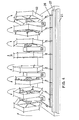
- the formers or swifts are preferably made of wire, and comprise a number of single stems extending radially from a hub.
- the stems are preferably made up of a number of sections, each thinner than the last as they extend radially, and made integral by welding, brazing or soldering.
- the resultant flexibility provides the desired resilience or whip.
- At least one of the stems is preferably collapsible, more preferably telescopic, and provided with a wing nut to lock the stem at a desired length.
- the stems widen at the outer ends to hild a hank of yarn, and are provided with radial projections at the edges to prevent the yarn sloughing off.
- the stems can also flex in the plane of the swift which helps in the drawing of yarn from the fabric and its winding on the swift.
- the drive from the motor to the formers is preferably through a shaft suspended by belts which transmit the drive to slip clutches adjacent the hubs of the formers.
- the hanging of the shaft makes for simplicity of construction and low maintenance.
- a supplementary use to which a machine according to the invention can be put is the splitting of yarns after unroving.
- unroving on a machine according to the invention leads to winding onto a single former.
- the yarns tend to be still combined, and require force to separate them.
- the yarns can be lead off the former together through a yarn guide, and then separated, passed through further guides, and wound onto separate formers.
- the slip clutches of the formers are adjusted in relation to each other to take account of the extent to which the individual yarns are held together so that the rewinding proceeds smoothly.
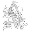
- a table top 15 is secured to a top frame 14 having leg holders 61 projecting downwards.
- the leg holders 61 are made rigid by leg braces 1, and have legs 67 with feet 72 projecting down to the ground.
- the pedestals 53 themselves are often omitted from the drawings in the interests of clarity.
- the motor M which is DC shunt-wound and subject to a thyristor controller 11.
- the motor M provides means both for rotating the formers F and for moving the traverse mechanism T.
- the drive to the formers F goes through a gearbox to a belt 4, a countershaft 68, pulleys 69, belts 51, and so up into the pedestals 53.
- the drive to the traverse mechanism T goes from the motor M through a worm gearbox 2, to a crank 7, and thence through a link 28, a ball joint 29, and arm 30 between wear strips 31 to a shaft 12.
- the shaft 12 is movable longitudinally to and fro, transversely with respect to the formers F, and is mounted on the table top 15 between plummer blocks 16.
- the shaft 12 carries pigtail guides 18 for the yarn.
- a cover 33 (Figure 1) for the upper end of the arm 30 and its union with the shaft 12.
- the traverse mechanism T is perhaps best shown in Figure 2, because in Figure 1 the link 28 is divided to illustrate its operation.
- the countershaft 68 which conveys the drive from the motor M to the formers F is mounted in plummer blocks 71 secured to a cross member 64 of a movable lower frame.
- the lower frame consists also of side bars 63 pivotally secured through rubber mountings 10 to fixing plates 13 projecting from the top frame 14 of the machine.
- the lower frame is suspended by the belts 51 from the pedestals 53, and hangs down with the assistance of weights 65 against the resilience of the rubber mountings 10.
- the lower frame has a bracket 9 carrying a hinge 8, to which the motor M is secured ensuring reasonable tension in the belt 4. This arrangement is perhaps best shown in Figure 2, as in Figure 1 the lower frame has been displaced at the mountings 10 for clarity of illustration.
- the slip clutches C between the belts 51 and the formers F are mounted on spindles 34 as best shown in Figure 2A.
- a clutch housing 39 is held fast on the spindle 34 by a grub screw 43.
- Inside the clutch housing 39 is a bearing holder 55 ( Figure 2A) which is fast on a nylon hub 56 of a former F.
- the bearing holder 55 has a conical face contacting ball bearings 37 and 41.
- the ball bearing 37 is held in contact with the holder 55 by a spring 36 and a grub screw 35.
- the ball bearing 41 is similarly secured by a piece of rubber cord 42 and a thumbscrew 44.
- the pressure of the ball bearings 37, 41 on the holder 55 can be varied by an operator by adjustment of the position of the grub screw 35, and more easily of the thumbscrew 44 respectively, so as to alter the pressure of the bearing holder 55 on a nylon friction disc 38 between the holder 55 and the housing 39. In practice, this pressure is adjusted to take account of the resistance of the yarn to unroving from the fabric.
- the spindle 34 is mounted with respect to the pedestal 53 by a plummer block 40 on each side of the pedestal as shown in Figure 1.
- the formers F each comprise a number of wire stems 54 projecting from the hub 56.
- the stems 54 are each made up of a number of sections, each thinner than the last as they extend radially, and made integral by brazing.
- One of the stems 54 of each former is provided with a wing nut 58 ( Figure 1) whereby the length of the stem 54 can be locked in any desired position and a hank of yarn can accordingly be removed from the former F.
- the stems 54 are each deformed laterally to increase flexibility, and at the end they have fittings 60 provided with radial projections at the edges to prevent the yarn sloughing off.
- the securing means S for a piece of knitted fabric is also best illustrated in Figure 1.
- a fabric holder bracket 19 projects from the top frame 14 of the machine, and bears a main beam 21 along the whole length of the machine.
- Fabric 80 ( Figure 3) for unroving is secured to the upper surface of the carpet 25 by means of a lock bar 27 under pressure from a rubber lock belt 23 at each end engaging with lock bushes 20.
- Yarn 82 ( Figure 3) is drawn off from the fabric 80 through pigtail guides 46 mounted on the ends of tension rods 45 projecting from the pedestals 53, and then passes through pigtail guides 18 secured to the shaft 12 of the traverse mechanism T and thence onto the formers F.
- the path of the yarn 82 may be varied either so as to omit the pigtail guides 46 and pass directly through the pigtail guides 18, or to pass through a pair of adjacent guides 18 after an intermediate passage through the guides 46.
Landscapes
- Engineering & Computer Science (AREA)
- Textile Engineering (AREA)
- Knitting Machines (AREA)
- Storing, Repeated Paying-Out, And Re-Storing Of Elongated Articles (AREA)
- Looms (AREA)
- Treatment Of Fiber Materials (AREA)
Claims (7)
Applications Claiming Priority (2)
| Application Number | Priority Date | Filing Date | Title |
|---|---|---|---|
| GB8019770 | 1980-06-17 | ||
| GB8019770 | 1980-06-17 |
Publications (2)
| Publication Number | Publication Date |
|---|---|
| EP0061447A1 EP0061447A1 (de) | 1982-10-06 |
| EP0061447B1 true EP0061447B1 (de) | 1984-11-07 |
Family
ID=10514099
Family Applications (1)
| Application Number | Title | Priority Date | Filing Date |
|---|---|---|---|
| EP81901139A Expired EP0061447B1 (de) | 1980-06-17 | 1981-05-11 | Maschine zum auflösen von strickwaren |
Country Status (7)
| Country | Link |
|---|---|
| US (1) | US4530137A (de) |
| EP (1) | EP0061447B1 (de) |
| JP (1) | JPS5926692B2 (de) |
| FI (1) | FI69650C (de) |
| RO (1) | RO86141B1 (de) |
| SU (1) | SU1358789A3 (de) |
| WO (1) | WO1981003670A1 (de) |
Families Citing this family (6)
| Publication number | Priority date | Publication date | Assignee | Title |
|---|---|---|---|---|
| JPS6199863U (de) * | 1984-12-06 | 1986-06-26 | ||
| TR199900813A2 (xx) | 1999-04-14 | 2000-11-21 | A�R�Kl� Mehmet | �rg� s�kme y�ntemi ve makinas� |
| FR2907799B1 (fr) * | 2006-10-30 | 2009-01-23 | Superba Sas | Procede de traitement de fils par tricotage-detricotage |
| CN105297274B (zh) * | 2015-11-05 | 2017-04-12 | 曾勇军 | 半自动拆片机 |
| CN109252283B (zh) * | 2018-11-12 | 2024-09-03 | 中山龙族自动化科技有限公司 | 一种电脑横机自动拆片装置 |
| CN113699672A (zh) * | 2020-07-29 | 2021-11-26 | 王卫星 | 一种线衣拆解熨直缠绕一体机及使用方法 |
Family Cites Families (18)
| Publication number | Priority date | Publication date | Assignee | Title |
|---|---|---|---|---|
| FR397598A (fr) * | 1908-12-18 | 1909-05-11 | Carl Wilhelm Pilscheur | Dévidoir pour machines à bobiner et leur équivalent |
| FR443293A (fr) * | 1912-04-13 | 1912-09-20 | Gustav Weissbach | Dévidoir commandé par friction et servant à renvider les fils de tissus composés de fils multiples |
| US1437341A (en) * | 1922-01-16 | 1922-11-28 | Dreaper William Porter | Manufacture of artificial filaments and the like |
| GB192663A (en) * | 1922-06-10 | 1923-02-08 | Arthur Urie | Domestic apparatus for winding wool and the like |
| FR596481A (fr) * | 1924-04-11 | 1925-10-24 | Ruegg J | Aspe pour machines à bobiner et machines à envider |
| FR607958A (fr) * | 1925-12-14 | 1926-07-12 | Appareil pour défaire les morceaux de tricot en double-chute et en jacquard en deux, trois, quatre couleurs ou plus | |
| FR628568A (fr) * | 1926-04-09 | 1927-10-26 | Dispositif démailleur pour tissus tricotés | |
| FR692548A (fr) * | 1929-03-28 | 1930-11-06 | Dévidoir réglable | |
| US2107385A (en) * | 1934-07-11 | 1938-02-08 | Rosedale Knitting Co Inc | Yarn winding machine |
| US2172114A (en) * | 1938-07-12 | 1939-09-05 | Howard Hosiery Company | Multiple thread back-winding machine |
| US3048343A (en) * | 1959-07-01 | 1962-08-07 | Leesona Corp | Textile winding machine |
| FR1299701A (fr) * | 1961-06-16 | 1962-07-27 | Machine à détricoter | |
| GB1135825A (en) * | 1965-05-18 | 1968-12-04 | Dobbie Ind Ltd | Method of skein dyeing yarn |
| US3413700A (en) * | 1966-12-19 | 1968-12-03 | Abowitz Alexander | Fabric unraveling machine |
| SU395530A1 (ru) * | 1971-12-24 | 1973-08-28 | Машина для роспуска трикотажного срыва | |
| CH568295A5 (de) * | 1973-07-13 | 1975-10-31 | Sandoz Ag | |
| DE2420625A1 (de) * | 1974-04-27 | 1975-11-13 | Metallgesellschaft Ag | Verfahren zum einstellen und konstanthalten einer definierten zugspannung in einem fadenstrang |
| SU742503A1 (ru) * | 1978-02-14 | 1980-06-25 | Центральное Проектно-Конструкторское И Технологическое Бюро Министерства Легкой Промышленности Латвийской Сср | Устройство дл распускани трикотажных изделий |
-
1981
- 1981-05-11 JP JP56501427A patent/JPS5926692B2/ja not_active Expired
- 1981-05-11 EP EP81901139A patent/EP0061447B1/de not_active Expired
- 1981-05-11 WO PCT/GB1981/000084 patent/WO1981003670A1/en active IP Right Grant
-
1982
- 1982-06-16 SU SU823473499A patent/SU1358789A3/ru active
- 1982-07-12 FI FI822479A patent/FI69650C/fi not_active IP Right Cessation
- 1982-07-16 RO RO108177A patent/RO86141B1/ro unknown
-
1984
- 1984-06-29 US US06/606,987 patent/US4530137A/en not_active Expired - Fee Related
Also Published As
| Publication number | Publication date |
|---|---|
| EP0061447A1 (de) | 1982-10-06 |
| SU1358789A3 (ru) | 1987-12-07 |
| RO86141A2 (ro) | 1985-03-15 |
| WO1981003670A1 (en) | 1981-12-24 |
| FI69650B (fi) | 1985-11-29 |
| US4530137A (en) | 1985-07-23 |
| FI69650C (fi) | 1986-03-10 |
| JPS5926692B2 (ja) | 1984-06-29 |
| RO86141B1 (ro) | 1985-03-31 |
| JPS57500835A (de) | 1982-05-13 |
| FI822479A0 (fi) | 1982-07-12 |
| FI822479L (fi) | 1982-07-12 |
Similar Documents
| Publication | Publication Date | Title |
|---|---|---|
| US4830298A (en) | Self-centering sheave for filaments | |
| EP0061447B1 (de) | Maschine zum auflösen von strickwaren | |
| EP0006507A2 (de) | Vorrichtung zum Abtrennen von Streifen von Rollen gewebter Textilien, die aus durch Hitze schweissbaren Fäden bestehen | |
| US4907323A (en) | Method and apparatus for making biased fabric | |
| US2448499A (en) | Method of producing strands of intertwisted glass fibers | |
| US2098418A (en) | Apparatus for equalizing the tension of threads | |
| US2467286A (en) | Apparatus for wrapping shrubs | |
| US2087606A (en) | Spinning apparatus | |
| US4094134A (en) | Thread end cutting apparatus in spinning machine | |
| US3145989A (en) | Spreading machine for fabric-like sheet materials | |
| EP0424573B1 (de) | Garn-Aufspulmaschine | |
| CN106629001B (zh) | 一种纱管分路上料装置 | |
| CS207626B2 (en) | Winding machine | |
| US2331454A (en) | Apparatus for unwinding thread packages | |
| US2957263A (en) | Floral roping machine | |
| CN220375981U (zh) | 一种胶膜厚度可控的数控纤维缠绕机 | |
| US2149238A (en) | Wire spooling machine | |
| US353036A (en) | Machine for making cord and rope | |
| US3405813A (en) | Conveyor for tobacco stitcher and looper mechanism | |
| CN114620518A (zh) | 一种无纺布分卷机 | |
| US1918285A (en) | Magazine spooling mechanism | |
| US4383402A (en) | Tangentially driven ring | |
| US328884A (en) | Machine foe covering coed with silk threads | |
| CN115520731A (zh) | 一种络筒机的纱线上蜡装置 | |
| DE1904357A1 (de) | Fadenspeicher- und -liefervorrichtung fuer Textilmaschinen |
Legal Events
| Date | Code | Title | Description |
|---|---|---|---|
| PUAI | Public reference made under article 153(3) epc to a published international application that has entered the european phase |
Free format text: ORIGINAL CODE: 0009012 |
|
| 17P | Request for examination filed |
Effective date: 19820531 |
|
| AK | Designated contracting states |
Designated state(s): DE FR GB |
|
| GRAA | (expected) grant |
Free format text: ORIGINAL CODE: 0009210 |
|
| AK | Designated contracting states |
Designated state(s): DE FR GB |
|
| REF | Corresponds to: |
Ref document number: 3167041 Country of ref document: DE Date of ref document: 19841213 |
|
| ET | Fr: translation filed | ||
| PLBE | No opposition filed within time limit |
Free format text: ORIGINAL CODE: 0009261 |
|
| STAA | Information on the status of an ep patent application or granted ep patent |
Free format text: STATUS: NO OPPOSITION FILED WITHIN TIME LIMIT |
|
| 26N | No opposition filed | ||
| PGFP | Annual fee paid to national office [announced via postgrant information from national office to epo] |
Ref country code: DE Payment date: 19890505 Year of fee payment: 9 |
|
| PGFP | Annual fee paid to national office [announced via postgrant information from national office to epo] |
Ref country code: FR Payment date: 19900419 Year of fee payment: 10 |
|
| PG25 | Lapsed in a contracting state [announced via postgrant information from national office to epo] |
Ref country code: DE Effective date: 19901002 |
|
| PGFP | Annual fee paid to national office [announced via postgrant information from national office to epo] |
Ref country code: GB Payment date: 19910501 Year of fee payment: 11 |
|
| PG25 | Lapsed in a contracting state [announced via postgrant information from national office to epo] |
Ref country code: FR Effective date: 19920131 |
|
| REG | Reference to a national code |
Ref country code: FR Ref legal event code: ST |
|
| PG25 | Lapsed in a contracting state [announced via postgrant information from national office to epo] |
Ref country code: GB Effective date: 19920511 |
|
| GBPC | Gb: european patent ceased through non-payment of renewal fee |
Effective date: 19920511 |