EP0061166A2 - Pressure chamber abrasive blasting device - Google Patents
Pressure chamber abrasive blasting device Download PDFInfo
- Publication number
- EP0061166A2 EP0061166A2 EP82102253A EP82102253A EP0061166A2 EP 0061166 A2 EP0061166 A2 EP 0061166A2 EP 82102253 A EP82102253 A EP 82102253A EP 82102253 A EP82102253 A EP 82102253A EP 0061166 A2 EP0061166 A2 EP 0061166A2
- Authority
- EP
- European Patent Office
- Prior art keywords
- blasting
- pressure medium
- container
- control valve
- hose
- Prior art date
- Legal status (The legal status is an assumption and is not a legal conclusion. Google has not performed a legal analysis and makes no representation as to the accuracy of the status listed.)
- Granted
Links
- 238000005270 abrasive blasting Methods 0.000 title abstract 2
- 238000005422 blasting Methods 0.000 claims abstract description 102
- XLYOFNOQVPJJNP-UHFFFAOYSA-N water Substances O XLYOFNOQVPJJNP-UHFFFAOYSA-N 0.000 claims abstract description 14
- 239000003795 chemical substances by application Substances 0.000 claims description 26
- 230000008878 coupling Effects 0.000 claims description 4
- 238000010168 coupling process Methods 0.000 claims description 4
- 238000005859 coupling reaction Methods 0.000 claims description 4
- 238000009423 ventilation Methods 0.000 claims description 3
- 239000012530 fluid Substances 0.000 claims 1
- 238000007789 sealing Methods 0.000 abstract 3
- 239000000945 filler Substances 0.000 abstract 1
- 238000011144 upstream manufacturing Methods 0.000 abstract 1
- 239000000428 dust Substances 0.000 description 10
- 238000000034 method Methods 0.000 description 3
- 230000008569 process Effects 0.000 description 3
- 239000003082 abrasive agent Substances 0.000 description 2
- 230000008901 benefit Effects 0.000 description 2
- 238000004140 cleaning Methods 0.000 description 2
- 239000002245 particle Substances 0.000 description 2
- 238000005245 sintering Methods 0.000 description 2
- 238000013022 venting Methods 0.000 description 2
- 230000009471 action Effects 0.000 description 1
- 238000011001 backwashing Methods 0.000 description 1
- 230000000903 blocking effect Effects 0.000 description 1
- 238000007664 blowing Methods 0.000 description 1
- 238000003825 pressing Methods 0.000 description 1
- 230000005855 radiation Effects 0.000 description 1
- 238000010992 reflux Methods 0.000 description 1
- 230000000717 retained effect Effects 0.000 description 1
Images
Classifications
-
- B—PERFORMING OPERATIONS; TRANSPORTING
- B24—GRINDING; POLISHING
- B24C—ABRASIVE OR RELATED BLASTING WITH PARTICULATE MATERIAL
- B24C7/00—Equipment for feeding abrasive material; Controlling the flowability, constitution, or other physical characteristics of abrasive blasts
- B24C7/0046—Equipment for feeding abrasive material; Controlling the flowability, constitution, or other physical characteristics of abrasive blasts the abrasive material being fed in a gaseous carrier
- B24C7/0069—Equipment for feeding abrasive material; Controlling the flowability, constitution, or other physical characteristics of abrasive blasts the abrasive material being fed in a gaseous carrier with means for preventing clogging of the equipment or for preventing abrasive entering the airway
Definitions
- the invention relates to a pressure chamber blasting device consisting of a blasting agent container with a blasting agent filling opening which can be closed by means of a cone and a blasting nozzle connected to the blasting agent container by means of a blasting hose, the blasting agent container and the blasting hose being connected to a compressed air source via a pressure medium control valve and the closing cone in the pressure medium supply line leading into the container is guided such that it is actuated in the closing direction by the inflowing pressure medium.
- the known pressure chamber blasting devices have proven to be very effective in that good blasting results are achieved with their help.
- the blasting agent container remains under pressure after the pressure medium control valve is closed and the pressure relief or venting until the air stored in the blasting agent container is completely blown off after the control valve designed as a two-way valve is switched off the blasting hose or via the blasting nozzle is possible with the subsequent blasting of blasting media.
- the aim of the present invention is to provide a pressure chamber jet device of the type described, in which the pressure relief of the container and the pressure medium lines takes place automatically and the invention consists in that a three-way valve is provided as the control valve.
- the invention provides a pressure chamber blasting device in which, at the same time as the pressure medium flow is blocked, the container is vented by automatically opening the container to the atmosphere via the pressure medium supply line, which now serves as the ventilation line, and the R port of the control valve.
- the vent valve attached to the boiler can therefore be omitted, all the required functions are controlled in one valve.
- Another significant advantage of the pressure chamber blasting device according to the invention can also be seen in the fact that the pressure relief does not take place directly via a valve that opens directly to the atmosphere, but via the closing cone guide located in the dome of the container, through which no or at most a negligibly small amount of wear-causing Abrasives are carried away to the outside.
- the control valve is formed by a mechanical, rotary lever-operated three-way ball valve with four housing connections, of which one connection to the boiler on the one hand and lead to the blasting hose on the other hand, while one of the two remaining connections serves as a vent connection and is expediently provided with a quick-release coupling for attaching a sound-stop vent cartridge.
- Venting cartridge as a result of the resulting closure of the vent opening, an additional valve position can be achieved in which the entire amount of air fed in - for example for the purpose of blowing the container through for cleaning purposes - can be guided into the boiler by blocking the connection leading to the blasting hose.
- a two-way / three-way valve pneumatically controlled by a two / three-way valve as a pushbutton is provided as the pressure-medium control valve, which controls a common pressure-medium line leading both to the blasting agent container and to the blasting hose, a water separator being arranged between the pressure medium control valve and the container is.
- the pressure chamber blasting device designed in this way fulfills all technical and safety requirements for such a device insofar as not only the device is automatically vented at the same time as the pressure medium flow is blocked, but the entire pressure medium and blasting medium control from the blasting nozzle takes place in the Way that the pressure medium control valve is reversed as soon as the button is closed, thereby relieving pressure via the pressure medium line.
- the water separator downstream of the pressure control valve serves as a special advantage in this air flow direction as a self-cleaning dust filter, by means of which both the pressure control valve and the atmosphere are reliably protected from any type of entrained dust or blasting agent, and this immediately when the blasting process is resumed through the container or compressed air flowing into the blasting hose is cleaned by backwashing.
- the water separator is expediently arranged in the pressure medium line between the pressure medium control valve and the line branch, wherein a non-return valve is arranged in the line leading to the blasting hose as far as possible before it flows into the blasting hose - ie immediately behind the branch.
- the check valve itself is thereby protected against wear, and the water separator, which acts as a filter in this operating phase, is also protected against overload by an excessive amount of blasting medium flowing back.
- the blasting agent entrained in the blasting hose with the refluxing air is therefore only returned to the container and held back by the blasting agent column, whereby blasting agent entrained from the blasting agent column or entrained dust particles are essentially retained at the closing cone of the container filling opening. Any fine dust that is entrained is then filtered out in the water separator.
- 1 denotes the blasting agent container of a pressure chamber blasting device, which is provided with a blasting agent filling opening 3 which can be closed by means of the closing key 2 and a blasting nozzle (not shown) connected to the blasting agent container 1 by means of blasting hose 4, the blasting agent container 1 and the blasting hose 4 being provided via a pressure medium control valve are connected to a compressed air source and the closing cone 2 is guided in the pressure medium supply line 6 leading into the container such that it is separated from the inflowing pressure medium in Closing direction is operated.
- the pressure medium control valve 5 is formed by a pneumatically controlled two / three-way valve, which is arranged by means of a two / three-way valve as a button 7 arranged on the blasting nozzle and which both the line 6 leading to the blasting agent container and the line 8 leading to the blasting hose controls that are led to the branch 10 in a common line q .
- a water separator 9 is arranged between the pressure medium valve 5 and the container 1. The water separator 9 is arranged in the pressure medium line between the pressure medium control valve and the branching 10 of the lines 6, 8, a check valve 12 being arranged in the line 8 leading to the blasting hose 4 immediately behind the branching 10.
- the Druckweq is released from the compressor feed line 13 to the Z connection of the pressure medium control valve, whereby the pressure chamber jet device is pressurized with compressed air by closing the R connection and opening the pressure medium path from P to A of this valve.
- the closing cone 2 is raised, thus closing the blasting agent filling opening 3 and consequently building up pressure in the container 1, the check valve 12 is opened at the same time as the pressure builds up, and the pressure medium path is released into the blasting hose, into which the blasting medium comes out of the container 1 is fed into the mouth 11 under the pressure building up there.
- the separator 9 acts as a water separator, at the sintering insert 9a of which the moisture introduced with the air condenses, which drips into the bottom of the separator and can be removed from time to time via the bottom valve.
- the P connection of the pressure medium control valve 5 is closed and its R connection is opened to A, whereby the entire device is opened to the atmosphere.
- the check valve 12 is first closed, thereby preventing the air from flowing back via the line 8 and, in particular, from the blasting hose 4 flowing back beyond the valve. Rather, the pressure medium and blasting medium return flow takes place completely via the container 1, in which the blasting medium flowing back from the blasting hose 4 is collected. Any entrained items from the abrasive column Abrasives and entrained dust particles primarily catch on the closing cone 2 and fall back into the container. Residual dust quantities passing into the line 6 are caught in the sintering insert 9a of the water separator 9, which acts as a dust filter in this phase. The valve 5 and the atmosphere are completely protected against dust.
- the sintered insert of the water separator 9 is automatically cleaned of the collected dust again in the manner of a backwash filter.
- control valve is a mechanical three-way ball valve 18 with four connections 13, 15, which is actuated by means of a pivoting lever 14 , 16, 17 formed, of which the connection 13 serves to connect to the compressor (not shown), the two mutually opposite connections 15, 16 serve to connect to the boiler (connection 15) or blasting hose (connection 16), during the Connection 17 serves as a vent connection, which is provided with a quick-release coupling 19 for attaching a sound stop vent cartridge 20.
- a water separator 9, 9a is provided between the three-way ball valve 18 and the blasting agent container 1, but in this embodiment provided with a mechanical control it is also unnecessary or can be arranged elsewhere, for example between the compressor and the ball valve.
- FIG. 2 first of all creates a simple mechanical single-lever control for pressure chamber blasting units, the arrangement in the operating position being shown in FIG. 2 in which, when the connection 17 is closed, there is a connection from the compressor 13 both to the container and to the blasting hose.
- Fig. 3 shows the closed position in which both the boiler and the blasting hose are simultaneously connected to the atmosphere and are thus relieved of pressure.
- Fig. 4 shows a rinsing position of the ball valve, the effectiveness of which requires the uncoupling of the cartridge 20 and thus the automatic closing of the quick-release coupling 19. In this case, the entire inflowing air is passed over the container with the jet hose line 8 closed.
Landscapes
- Mechanical Engineering (AREA)
- Engineering & Computer Science (AREA)
- Cleaning In General (AREA)
- Knitting Machines (AREA)
- Air Bags (AREA)
- Forklifts And Lifting Vehicles (AREA)
- Spray Control Apparatus (AREA)
- Analysing Materials By The Use Of Radiation (AREA)
- Safety Valves (AREA)
- Processing Of Meat And Fish (AREA)
- Electrical Discharge Machining, Electrochemical Machining, And Combined Machining (AREA)
- Polishing Bodies And Polishing Tools (AREA)
- Dental Tools And Instruments Or Auxiliary Dental Instruments (AREA)
- Filling Or Discharging Of Gas Storage Vessels (AREA)
Abstract
Description
Die Erfindung betrifft ein Druckkammerstrahlgerät, bestehend aus einem Strahlmittelbehälter mit einer mittels Schließkegel verschließbaren Strahlmitteleinfüllöffnung und einer mittels Strahlschlauch mit dem Strahlmittelbehälter verbundenen Strahldüse, wobei der Strahlmittelbehälter und der Strahlschlauch über ein Druckmittelsteuerventil mit einer Druckluftquelle verbunden sind und der Schließkegel in der in den Behälter führenden Druckmittelzuführungsleitung derart geführt ist, daß er von dem einströmenden Druckmittel in Schließrichtung betätigt wird.The invention relates to a pressure chamber blasting device consisting of a blasting agent container with a blasting agent filling opening which can be closed by means of a cone and a blasting nozzle connected to the blasting agent container by means of a blasting hose, the blasting agent container and the blasting hose being connected to a compressed air source via a pressure medium control valve and the closing cone in the pressure medium supply line leading into the container is guided such that it is actuated in the closing direction by the inflowing pressure medium.
Die bekannten Druckkammerstrahlgeräte haben sich insofern bestens bewährt, als mit ihrer Hilfe gute Strahlergebnisse erzielt werden. Es bestehen jedoch eine Reihe von Nachteilen funktioneller Art, so insbesondere der Nachteil, daß der Strahlmittelbehälter nach dem Schließen des Druckmittelsteuerventils zunächst unter Druck verbleibt und die Druckentlastung bzw. Entlüftung bis zum vollständigen Abblasen der im Strahlmittelbehälter gespeicherten Luft nach Abstellung des als Zweiwegeventil ausgeführten Steuerventils über den Strahlschlauch bzw. über die Strahldüse unter entsprechend Nachverstrahlung von Strahlmittel möglich ist.The known pressure chamber blasting devices have proven to be very effective in that good blasting results are achieved with their help. However, there are a number of disadvantages of a functional nature, in particular the disadvantage that the blasting agent container remains under pressure after the pressure medium control valve is closed and the pressure relief or venting until the air stored in the blasting agent container is completely blown off after the control valve designed as a two-way valve is switched off the blasting hose or via the blasting nozzle is possible with the subsequent blasting of blasting media.
Zur Vermeidung dieses Nachteils ist es bekannt, die Düse mit einem Sperrventil zu versehen und an dem Strahlmittelbehälter zur Ermöglichung einer Druckentlastung des Behälters ein weiteres Ventil als Entlüftungsventil anzubringen, über das nach der Strahlung der Behälter, beispielsweise zum Zwecke der Nachfüllung von Strahlmittel, druckentlastet werden kann.To avoid this disadvantage, it is known to provide the nozzle with a shut-off valve and to attach a further valve as a vent valve to the blasting agent container to enable pressure relief of the container, via which pressure is relieved after the radiation of the container, for example for the purpose of refilling blasting agent can.
Es wird hierdurch zwar ein Abstellen des Gerätes durch einen an der Strahldüse selbst angebrachten Absteller ermöglicht, so daß es der andernfalls erforderlichen Zurücklegung eines mehr oder weniger weiten Weges bis zum gerätefesten Hauptsteuerventil unter vollem Strahlmitteldurchfluß nicht mehr bedarf, die nach dem Strahlvorgang erforderliche und vorgeschriebene Druckentlastung des Strahlmittelbehälters kann jedoch nach wie vor nur am Behälter selbst erfolgen, wobei bei der Öffnung des Ventils von der plötzlich aus dem Strahlschlauch durch die Strahlmittelsäule hindurch rückfliessenden Luft ebenfalls große Mengen an Strahlmittel mitgerissen und aus dem Strahlmittelbehälter durch das Entlüftungsventil ausgetragen werden, das demgemäß durch das seiner Natur nach scharfe Strahlmittel einem großen Verschleiß unterliegt. Darüberhinaus ergeben sich hierdurch größere Mengen an Strahlmittelverlusten sowie eine insbesondere in geschlossenen Räumen untragbare Verstaubung der Umgebung. Ebenso unterliegt der an der Strahldüse angebrachte Absteller einem ganz erheblichen Verschleiß, da während der Verstrahlung das gesamte Strahlmittel durch die Kegelbohrung des Abstellers fließt.This makes it possible to switch off the device by a switch attached to the blasting nozzle itself, so that it otherwise required covering a more or less long way to the device-fixed main control valve with full blasting medium flow no longer required, however, the pressure relief of the blasting medium container required and prescribed after the blasting process can still only be carried out on the container itself, when suddenly opening the valve large amounts of blasting media are also entrained in the blasting hose flowing back through the blasting media column and are discharged from the blasting media container through the vent valve, which is accordingly subject to great wear due to the nature of the blasting media which is sharp. In addition, this results in larger amounts of abrasive loss and dust in the environment, which is particularly intolerable in closed rooms. Likewise, the rack attached to the blasting nozzle is subject to very considerable wear, since the entire blasting medium flows through the cone bore of the rack during the blasting process.
Ziel der vorliegenden Erfindung ist die Schaffung eines Druckkammerstrahlgerätes der beschriebenen Art, bei dem die Druckentlastung des Behälters und der Druckmittelleitungen selbststätig erfolgt und die Erfindung besteht darin, daß als Steuerventil ein Dreiwegeventil vorgesehen ist.The aim of the present invention is to provide a pressure chamber jet device of the type described, in which the pressure relief of the container and the pressure medium lines takes place automatically and the invention consists in that a three-way valve is provided as the control valve.
Durch die Erfindung ist ein Druckkammerstrahlgerät geschaffen, bei dem gleichzeitig mit dem Sperren des Druckmittelzuflusses die Entlüftung des Behälters dadurch erfolgt, daß der Behälter über die nunmehr als Entlüftungsleitung dienende Druckmittelzuführungsleitung sowie den R-Anschluß des Steuerventils automatisch gegen Atmosphäre geöffnet wird. Es kann somit das zusätzlich am Kessel angebrachte Entlüftungsventil entfallen, es werden alle erforderlichen Funktionen in einem Ventil gesteuert. Ein weiterer wesentlicher Vorteil des erfindungsgemäßen Druckkammerstrahlgerätes ist auch darin zu sehen, daß die Druckentlastung nicht auf direktem Wege über ein unmittelbar gegen Atmosphäre öffnendes Ventil erfolgt sondern über die im Dom des Behälters sitzende Schließkegelführung, durch die hindurch keine oder allenfalls vernachlässigbar kleine Menge an Verschleiß verursachendem Strahlmittel nach außen mitgerissen werden.The invention provides a pressure chamber blasting device in which, at the same time as the pressure medium flow is blocked, the container is vented by automatically opening the container to the atmosphere via the pressure medium supply line, which now serves as the ventilation line, and the R port of the control valve. The vent valve attached to the boiler can therefore be omitted, all the required functions are controlled in one valve. Another significant advantage of the pressure chamber blasting device according to the invention can also be seen in the fact that the pressure relief does not take place directly via a valve that opens directly to the atmosphere, but via the closing cone guide located in the dome of the container, through which no or at most a negligibly small amount of wear-causing Abrasives are carried away to the outside.
In einer Ausführungsform der Erfindung wird das Steuerventil von einem mechanischen, drehhebelbetätigten Dreiwegekugelhahn mit vier Gehäuseanschlüssen gebildet, von denen je ein Anschluß zum Kessel einerseits und zum Strahlschlauch andererseits führen, während der eine der beiden verbleibenden Anschlüsse als Entlüftungsanschluß dient und zweckmäßig mit einer Schnellverschluß-Kupplung zur Anbringung einer Schallstop-Entlüftungspatrone versehen ist. Es ist auf diese Weise eine einfache Einhebel-Handsteuerung geschaffen, mit der durch einfaches Umlegen des Handhebels in die Ventilschließstellung gleichzeitig die Trennung der Kompressor-Zuleitung zum Behälter sowie die Öffnung des Kessels und des Strahlschlauches gegen die Atmosphäre erfolgt, wobei durch Abkuppeln der Schallstop-Entlüftungspatrone infolge des hierdurch bewirkten Verschlusses der Entlüftungsöffnung eine zusätzliche Ventilstellung erreicht werden kann, in der die gesamte eingespeiste Luftmenge - etwa zum Zwecke des Durchblasens des Behälters zu Reinigungszwecken - unter Sperrung des zum Strahlschlauch führenden Anschlusses in den Kessel geführt werden kann.In one embodiment of the invention, the control valve is formed by a mechanical, rotary lever-operated three-way ball valve with four housing connections, of which one connection to the boiler on the one hand and lead to the blasting hose on the other hand, while one of the two remaining connections serves as a vent connection and is expediently provided with a quick-release coupling for attaching a sound-stop vent cartridge. In this way, a simple single-lever manual control is created, with which the compressor supply line to the tank and the opening of the boiler and the blasting hose against the atmosphere are simultaneously separated by simply moving the hand lever into the valve closing position. Venting cartridge, as a result of the resulting closure of the vent opening, an additional valve position can be achieved in which the entire amount of air fed in - for example for the purpose of blowing the container through for cleaning purposes - can be guided into the boiler by blocking the connection leading to the blasting hose.
In einer besonders vorteilhaften Ausführungsform ist als Druckmittelsteuerventil ein von einem Zwei-/Dreiwegeventil als Taster pneumatisch gesteuertes Zwei-/Dreiwegeventil vorgesehen, das eine gemeinsame, sowohl zum Strahlmittelbehälter als auch zum Strahlschlauch führende Druckmittelleitung steuert, wobei zwischen dem Druckmittelsteuerventil und dem Behälter ein Wasserabscheider angeordnet ist. Das in dieser Weise ausgebildete Druckkammerstrahlgerät erfüllt alle gebrauchstechnisch und sicherheitstechnisch an ein derartiges Gerät zu stellenden Anforderungen insofern, als nicht nur eine selbsttätige Entlüftung des Geräte gleichzeitig mit der Sperrung des Druckmittelzuflusses erfolgt sondern darüberhinaus die gesamte Druckmittel- und Strahlmittelsteuerung von der Strahldüse aus erfolgt in der Weise, daß unmittelbar mit dem Schließen des Tasters das Druckmittelsteuerventil umgesteuert wird und hierdurch eine Druckentlastung über die Druckmittelleitung erfolgt. Hierbei dient als besonderer Vorteil der dem Druckmittelsteuerventil nachgeordnete Wasserabscheider in dieser Luftströmrichtung als selbstreinigendes Staubfilter, durch das sowohl das Druckmittelsteuerventil als auch die Atmosphäre zuverlässig vor jeder Art mitgerissenem Staub bzw. Strahlmittel geschützt und das unmittelbar bei Wiederaufnahme des Strahlvorganges durch die nunmehr wieder in den Behälter bzw. den Strahlschlauch einströmende Druckluft durch Rückspülung gereinigt wird.In a particularly advantageous embodiment, a two-way / three-way valve pneumatically controlled by a two / three-way valve as a pushbutton is provided as the pressure-medium control valve, which controls a common pressure-medium line leading both to the blasting agent container and to the blasting hose, a water separator being arranged between the pressure medium control valve and the container is. The pressure chamber blasting device designed in this way fulfills all technical and safety requirements for such a device insofar as not only the device is automatically vented at the same time as the pressure medium flow is blocked, but the entire pressure medium and blasting medium control from the blasting nozzle takes place in the Way that the pressure medium control valve is reversed as soon as the button is closed, thereby relieving pressure via the pressure medium line. The water separator downstream of the pressure control valve serves as a special advantage in this air flow direction as a self-cleaning dust filter, by means of which both the pressure control valve and the atmosphere are reliably protected from any type of entrained dust or blasting agent, and this immediately when the blasting process is resumed through the container or compressed air flowing into the blasting hose is cleaned by backwashing.
Der Wasserabscheider ist in der Druckmittelleitung zweckmäßig zwischen dem Druckmittelsteuerventil und der Leitungsverzweigung angeordnet, wobei in der zum Strahlschlauch führenden Leitung in einer möglichst großen Entfernung vor deren Einmündung in den Strahlschlauch - d.h. unmittelbar hinter der Verzweigung - ein Rückschlagventil angeordnet ist. Durch die Einbringung eines Rückschlagventils und insbesondere seine Anordnung in möglichst weitem Abstand vor der Einmündung in den Strahlschlauch, wird erreicht, daß bei Schließen des Tastventils und bei dem hierdurch bedingten Öffnen des Druckmittelsteuerventils gegen Atmosphäre die in dieser Verzweigung rückströmende Luft das Rückschlagventil noch im Bereich der Luftsäule schließt, d.h. bevor das mit der Luft mitqerissene Strahlmittel das Rückschlagventil erreicht oder gar passiert hat. Es wird hierdurch das Rückschlagventil selbst gegen Verschleiß geschützt, weiterhin der in dieser Betriebsphase als Filter wirkende Wasserabscheider qegen Überbelastung durch eine übermäßige Menge an rückströmendem Strahlmittel. Das im Strahlschlauch befindliche mit der rückfließenden Luft mitgerissene Strahlmittel wird somit ausschließlich in den Behälter zurückgebracht und von der Strahlmittelsäule zurückgehalten, wobei etwa aus der Strahlmittelsäule mitgerissenes Strahlmittel bzw. mitgerissene Staubanteile im wesentlichen am Schließkegel der Behältereinfüllöffnung zurückgehalten werden. Dann noch evtl. mitgerissene Feinstaubteile werden im Wasserabscheider ausgefiltert.The water separator is expediently arranged in the pressure medium line between the pressure medium control valve and the line branch, wherein a non-return valve is arranged in the line leading to the blasting hose as far as possible before it flows into the blasting hose - ie immediately behind the branch. By introducing a check valve and in particular its arrangement as far as possible before the junction in the blasting hose, it is achieved that when the pushbutton valve is closed and the pressure medium control valve is opened to the atmosphere due to this, the air flowing back in this branching the check valve still in the area of Air column closes, ie before the blasting medium entrained in the air has reached or even passed the check valve. The check valve itself is thereby protected against wear, and the water separator, which acts as a filter in this operating phase, is also protected against overload by an excessive amount of blasting medium flowing back. The blasting agent entrained in the blasting hose with the refluxing air is therefore only returned to the container and held back by the blasting agent column, whereby blasting agent entrained from the blasting agent column or entrained dust particles are essentially retained at the closing cone of the container filling opening. Any fine dust that is entrained is then filtered out in the water separator.
Die Erfindung ist in der Zeichnung beispielsweise veranschaulicht. Es zeigen
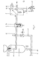
- Fig. l die schematische Darstellung eines Druckkammerstrahlgerätes mit selbsttätig pneumatisch gesteuertem Regelventil;
- Fig. 2 ein Druckkammerstrahlgerät mit handgesteuertem Einhebelsteuerventil;
- Fig. 3 das Ventil gemäß Fig. 2 in "Aus"-Stellung;
- Fig. 4 das Ventil gemäß Fig 2 in Spülstellung.
- Fig. L shows the schematic representation of a pressure chamber blasting device with automatically pneumatically controlled control valve;
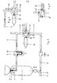
- 2 shows a pressure chamber blasting device with a manually controlled single-lever control valve;
- 3 shows the valve according to FIG. 2 in the “off” position;
- 4 shows the valve according to FIG. 2 in the rinsing position.
In der Zeichnung ist mit 1 der Strahlmittelbehälter eines Druckkammerstrahlgerätes bezeichnet, der mit einer mittels Schließkeqel 2 verschließbaren Strahlmitteleinfüllöffnung 3 und einer mittels Strahlschlauch 4 mit dem Strahlmittelbehälter 1 verbundenen Strahldüse (nicht gezeichnet) versehen ist, wobei der Strahlmittelbehälter 1 und der Strahlschlauch 4 über ein Druckmittelsteuerventil mit einer Druckluftquelle verbunden sind und der Schließkegel 2 in der in den Behälter führenden Druckmittelzuführungsleitung 6 derart geführt ist, daß er von dem einströmenden Druckmittel in Schließrichtung betätigt wird.In the drawing, 1 denotes the blasting agent container of a pressure chamber blasting device, which is provided with a blasting
Bei der in Fig. 1 wiedergegebenen Ausführungsform ist das Druckmittelsteuerventil 5 von einem mittels Zwei-/Dreiwegeventil als an der Strahldüse angeordnetem Taster 7 pneumatisch gesteuerten Zwei-/Dreiwegeventil gebildet, das sowohl die zum Strahlmittelbehälter führende Leitung 6 als auch die zum Strahlschlauch führende Leitung 8 steuert, die bis zur Verzweiqung 10 in einer gemeinsamen Leitunq geführt sind. Zwischen dem Druckmittelventil 5 und dem Behälter 1 ist ein Wasserabscheider 9 anqeordnet. Der Wasserabscheider 9 ist in der Druckmittelleitung zwischen dem Druckmittelsteuerventil und der Verzweigung 10 der Leitungen 6, 8 angeordnet, wobei in der zum Strahlschlauch 4 führenden Leitung 8 unmittelbar hinter der Verzweiqunq 10 ein Rückschlagventil 12 angeordnet ist.In the embodiment shown in FIG. 1, the pressure
Durch Betätigung des Tasters 7 wird der Druckweq von der Kompressorzuleitunq 13 zum Z-Anschluß des Druckmittelsteuerventils freigegeben, wodurch unter Schließen des R-Anschlusses und Öffnen des Druckmittelweges von P nach A dieses Ventils das Druckkammerstrahlqerät mit Druckluft beaufschlagt wird. Unter der Wirkung der einströmenden Druckluft wird der Schließkegel 2 gehoben, somit die Strahlmitteleinfüllöffnung 3 geschlossen und infolgedessen im Behälter 1 Druck aufgebaut, es wird gleichzeitig mit dem Druckaufbau das Rückschlagventil 12 geöffnet und der Druckmittelweg in den Strahlschlauch freigeqeben, in den das Strahlmittel aus dem Behälter 1 unter dem sich dort aufbauenden Druck in die Einmündung 11 eingespeist wird. In dieser Betriebsphase wirkt der Abscheider 9 als Wasserabscheider, an dessen Sintereinsatz 9a sich die mit der Luft eingebrachte Feuchtigkeit niederschlägt, die in den Sumpf des Abscheiders abtropft und von Zeit zu Zeit über das Bodenventil abgezoqen werden kann.By pressing the
Beim Entlasten des Tasters 7 wird der P-Anschluß des Druckmittelsteuerventils 5 geschlossen und sein R-Anschluß gegen A geöffnet, wodurch das gesamte Geräte gegen Atmosphäre geöffnet wird. Infolge der Druckentlastung wird zunächst das Rückschlagventil 12 geschlossen, wodurch ein Rückströmen der Luft über die Leitung 8 und insbesondere ein Rückfließen von Strahlmittel aus dem Strahlschlauch 4 über das Ventil hinaus verhindert ist. Der Druckmittel- und Strahlmittelrückfluß erfolgt vielmehr vollständig über den Behälter 1, in dem das aus dem Strahlschlauch 4 rückfließende Strahlmittel aufgefangen wird. Aus der Strahlmittelsäule eventuell mitgerissenes Strahlmittel und mitgerissene Staubteile fangen sich primär am Schließkegel 2 und fallen in den Behälter zurück, in die Leitung 6 übertretende Reststaubmengen werden im Sintereinsatz 9a des in dieser Phase als Staubfilter wirkenden Wasserabscheiders 9 gefangen. Das Ventil 5 und die Atmosphäre sind vollständig gegen Staub geschützt.When the
Während der nachfolgenden Betriebsphase wird der Sintereinsatz des Wasserabscheiders 9 selbsttätig nach Art eines Rückspülfilters wieder unmittelbar von dem aufgefangenen Staub gereinigt.During the subsequent operating phase, the sintered insert of the
Bei der in den Fig. 2 bis 4 - in denen im übrigen die einander entsprechenden Teile mit denselben Bezugsziffern wie in Fig. l bezeichnet sind - wiedergegebenen Ausführungsform ist das Steuerventil von einem mechanischen, mittels Schwenkhebel 14 betätigten Dreiwegekugelhahn 18 mit vier Anschlüssen 13, 15, 16, 17 gebildet, von denen der Anschluß 13 der Verbindung zum Kompressor (nicht dargestellt) dient, die beiden einander in Flucht gegenüberliegenden Anschlüsse 15, 16 dienen der Verbindung zum Kessel (Anschluß 15) bzw. Strahlschlauch (Anschluß 16), während der Anschluß 17 als Entlüftungsanschluß dient, der mit einer Schnellverschlußkupplung 19 zum Anbringen einer Schallstop-Entlüftungspatrone 20 versehen ist. Auch im Falle dieser Ausführungsform ist zwischen dem Dreiwegekugelhahn 18 und dem Strahlmittelbehälter 1 ein Wasserabscheider 9, 9a vorgesehen, der jedoch bei dieser mit einer mechanischen Steuerung versehenen Ausführungsform auch entbehrlich ist oder an anderer Stelle, beispielsweise zwischen Kompressor und Kugelhahn angeordnet sein kann.In the embodiment shown in FIGS. 2 to 4, in which the corresponding parts are designated with the same reference numbers as in FIG. 1, the control valve is a mechanical three-
Durch die in Fig. 2 dargestellte Ausführungsform ist erstmaliq eine einfache mechanische Einhebelsteuerung für Druckkammerstrahlgeräte geschaffen, wobei in Fig. 2 die Anordnung in Betriebsstellung wiedergegeben ist, in der bei geschlossenem Anschluß 17 eine Verbindung vom Kompressor 13 sowohl zum Behälter als auch zum Strahlschlauch besteht. Fig. 3 gibt die Schließstellunq wieder, in der gleichzeitiq sowohl der Kessel als auch der Strahlschlauch mit Atmosphäre verbunden und damit druckentlastet sind. Fig. 4 gibt eine Spülstellung des Kugelhahnes wieder, zu deren Wirksamkeit es des Abkuppelns der Patrone 20 und damit des selbsttätiqen Schließens der Schnellverschlußkupplung 19 bedarf. In diesem Falle wird die gesamte einströmende Luft unter Schluß der Strahlschlauchleitung 8 über den Behälter geleitet.The embodiment shown in FIG. 2 first of all creates a simple mechanical single-lever control for pressure chamber blasting units, the arrangement in the operating position being shown in FIG. 2 in which, when the connection 17 is closed, there is a connection from the
Claims (4)
Priority Applications (1)
| Application Number | Priority Date | Filing Date | Title |
|---|---|---|---|
| AT82102253T ATE15004T1 (en) | 1981-03-24 | 1982-03-19 | PRESSURE BLASTING DEVICE. |
Applications Claiming Priority (2)
| Application Number | Priority Date | Filing Date | Title |
|---|---|---|---|
| DE19813111581 DE3111581A1 (en) | 1981-03-24 | 1981-03-24 | PRINT CHAMBER JET |
| DE3111581 | 1981-03-24 |
Publications (3)
| Publication Number | Publication Date |
|---|---|
| EP0061166A2 true EP0061166A2 (en) | 1982-09-29 |
| EP0061166A3 EP0061166A3 (en) | 1982-10-27 |
| EP0061166B1 EP0061166B1 (en) | 1985-08-21 |
Family
ID=6128159
Family Applications (1)
| Application Number | Title | Priority Date | Filing Date |
|---|---|---|---|
| EP82102253A Expired EP0061166B1 (en) | 1981-03-24 | 1982-03-19 | Pressure chamber abrasive blasting device |
Country Status (5)
| Country | Link |
|---|---|
| EP (1) | EP0061166B1 (en) |
| AT (1) | ATE15004T1 (en) |
| DE (1) | DE3111581A1 (en) |
| DK (1) | DK169205B1 (en) |
| FI (1) | FI72448C (en) |
Cited By (4)
| Publication number | Priority date | Publication date | Assignee | Title |
|---|---|---|---|---|
| EP0201145A1 (en) * | 1985-05-07 | 1986-11-12 | Rijndelta Coating Technieken B.V. | Grit blasting apparatus |
| WO1991000164A1 (en) * | 1989-06-24 | 1991-01-10 | Sigrid Keizers | Device for blasting with a moist granular agent |
| EP0530154A2 (en) * | 1991-06-19 | 1993-03-03 | C.I.E. DENTALFARM S.r.l. | A microsanding system |
| DE19521051A1 (en) * | 1995-06-09 | 1996-12-12 | Woma Maasberg Co Gmbh W | High-pressure water jet |
Families Citing this family (1)
| Publication number | Priority date | Publication date | Assignee | Title |
|---|---|---|---|---|
| DE3939420C2 (en) * | 1989-11-29 | 1995-06-22 | Neubauer Geb Costas Perez Merc | Method and device for cutting resistant materials with a water jet |
Citations (5)
| Publication number | Priority date | Publication date | Assignee | Title |
|---|---|---|---|---|
| BE409758A (en) * | ||||
| US2729917A (en) * | 1953-06-30 | 1956-01-10 | William C Gregory | Cleaning apparatus |
| US3084484A (en) * | 1960-11-17 | 1963-04-09 | Sylvania Electric Prod | Pneumatic abrasive cutting apparatus |
| US3148484A (en) * | 1963-01-15 | 1964-09-15 | Jaroco Internat Inc | Sandblast generator |
| FR1515965A (en) * | 1966-03-31 | 1968-06-13 | Compressed air sandblaster |
Family Cites Families (4)
| Publication number | Priority date | Publication date | Assignee | Title |
|---|---|---|---|---|
| US1171286A (en) * | 1912-04-22 | 1916-02-08 | Howard L Wadsworth | Sand-blast machine. |
| US3034263A (en) * | 1959-08-07 | 1962-05-15 | Ruric N Mcdaniel | Sand blasting apparatus |
| US3741738A (en) * | 1971-04-12 | 1973-06-26 | Pauli & Griffin Co | Abrasive blasting equipment and self-cleaning abrasive trap therefore |
| US4026072A (en) * | 1976-08-09 | 1977-05-31 | Dremann George H | Self-cleaning muffler for an abrasive blast system |
-
1981
- 1981-03-24 DE DE19813111581 patent/DE3111581A1/en active Granted
-
1982
- 1982-03-17 DK DK117882A patent/DK169205B1/en not_active IP Right Cessation
- 1982-03-19 EP EP82102253A patent/EP0061166B1/en not_active Expired
- 1982-03-19 AT AT82102253T patent/ATE15004T1/en not_active IP Right Cessation
- 1982-03-23 FI FI821011A patent/FI72448C/en not_active IP Right Cessation
Patent Citations (5)
| Publication number | Priority date | Publication date | Assignee | Title |
|---|---|---|---|---|
| BE409758A (en) * | ||||
| US2729917A (en) * | 1953-06-30 | 1956-01-10 | William C Gregory | Cleaning apparatus |
| US3084484A (en) * | 1960-11-17 | 1963-04-09 | Sylvania Electric Prod | Pneumatic abrasive cutting apparatus |
| US3148484A (en) * | 1963-01-15 | 1964-09-15 | Jaroco Internat Inc | Sandblast generator |
| FR1515965A (en) * | 1966-03-31 | 1968-06-13 | Compressed air sandblaster |
Cited By (6)
| Publication number | Priority date | Publication date | Assignee | Title |
|---|---|---|---|---|
| EP0201145A1 (en) * | 1985-05-07 | 1986-11-12 | Rijndelta Coating Technieken B.V. | Grit blasting apparatus |
| WO1991000164A1 (en) * | 1989-06-24 | 1991-01-10 | Sigrid Keizers | Device for blasting with a moist granular agent |
| EP0530154A2 (en) * | 1991-06-19 | 1993-03-03 | C.I.E. DENTALFARM S.r.l. | A microsanding system |
| EP0530154A3 (en) * | 1991-06-19 | 1993-04-07 | C.I.E. Dentalfarm S.R.L. | A microsanding system and a pneumatic valve used in the system |
| DE19521051A1 (en) * | 1995-06-09 | 1996-12-12 | Woma Maasberg Co Gmbh W | High-pressure water jet |
| DE19521051C2 (en) * | 1995-06-09 | 1998-04-09 | Woma Maasberg Co Gmbh W | High pressure water jet processing device |
Also Published As
| Publication number | Publication date |
|---|---|
| FI72448B (en) | 1987-02-27 |
| FI821011L (en) | 1982-09-25 |
| EP0061166A3 (en) | 1982-10-27 |
| ATE15004T1 (en) | 1985-09-15 |
| DK117882A (en) | 1982-09-25 |
| DE3111581C2 (en) | 1987-11-12 |
| EP0061166B1 (en) | 1985-08-21 |
| DE3111581A1 (en) | 1982-10-14 |
| DK169205B1 (en) | 1994-09-12 |
| FI821011A0 (en) | 1982-03-23 |
| FI72448C (en) | 1987-06-08 |
Similar Documents
| Publication | Publication Date | Title |
|---|---|---|
| DE4425863C2 (en) | Suction and blowing device | |
| DE102014009231B4 (en) | Shut-off filter apparatus | |
| EP1346700A1 (en) | Handpiece for abrasive blasting dental apparatus with protective filter | |
| CH675278A5 (en) | ||
| EP0061166A2 (en) | Pressure chamber abrasive blasting device | |
| DE2746037A1 (en) | High-pressure cleaning appts. with chemical action - has chemical suction switched on without interruption of work process | |
| WO2002090804A2 (en) | Sliding valve | |
| DE3239429A1 (en) | METHOD AND DEVICE FOR OPERATING A HIGH-PRESSURE HEATER | |
| DE3403197C2 (en) | ||
| DE69716693T2 (en) | Control device for a cleaning device for contaminated surfaces | |
| DE4101248C2 (en) | Flow valve | |
| DE10005656A1 (en) | Powder coating system | |
| DE19516740C2 (en) | Vacuum toilet system | |
| DE1813089A1 (en) | Device for loading a movable, flexible structure | |
| CH676330A5 (en) | ||
| DE102006009965B4 (en) | Extraction system for a machining machine | |
| DE693764C (en) | Device for rendering rock drilling dust harmless | |
| DE821356C (en) | Dirt trap for shut-off and regulating devices, especially for steam drains | |
| DE19823085C1 (en) | Spray head for remote cleaner | |
| DE2911112C2 (en) | ||
| EP1698389A1 (en) | Filter device for a dry, gaseous media | |
| EP0337936A1 (en) | Domestic water station | |
| DE19546042C1 (en) | Pressure-jet cleaning tool with visor-cleaning system | |
| DE492990C (en) | Spray device | |
| DE29619975U1 (en) | Spray device for the flat application of liquids |
Legal Events
| Date | Code | Title | Description |
|---|---|---|---|
| PUAI | Public reference made under article 153(3) epc to a published international application that has entered the european phase |
Free format text: ORIGINAL CODE: 0009012 |
|
| PUAL | Search report despatched |
Free format text: ORIGINAL CODE: 0009013 |
|
| AK | Designated contracting states |
Designated state(s): AT BE CH FR IT SE |
|
| AK | Designated contracting states |
Designated state(s): AT BE CH FR IT SE |
|
| 17P | Request for examination filed |
Effective date: 19821217 |
|
| ITF | It: translation for a ep patent filed | ||
| GRAA | (expected) grant |
Free format text: ORIGINAL CODE: 0009210 |
|
| AK | Designated contracting states |
Designated state(s): AT BE CH FR IT LI SE |
|
| REF | Corresponds to: |
Ref document number: 15004 Country of ref document: AT Date of ref document: 19850915 Kind code of ref document: T |
|
| ET | Fr: translation filed | ||
| PLBE | No opposition filed within time limit |
Free format text: ORIGINAL CODE: 0009261 |
|
| STAA | Information on the status of an ep patent application or granted ep patent |
Free format text: STATUS: NO OPPOSITION FILED WITHIN TIME LIMIT |
|
| 26N | No opposition filed | ||
| ITTA | It: last paid annual fee | ||
| EAL | Se: european patent in force in sweden |
Ref document number: 82102253.0 |
|
| PGFP | Annual fee paid to national office [announced via postgrant information from national office to epo] |
Ref country code: AT Payment date: 19980330 Year of fee payment: 17 |
|
| PGFP | Annual fee paid to national office [announced via postgrant information from national office to epo] |
Ref country code: SE Payment date: 19990315 Year of fee payment: 18 Ref country code: CH Payment date: 19990315 Year of fee payment: 18 |
|
| PG25 | Lapsed in a contracting state [announced via postgrant information from national office to epo] |
Ref country code: AT Free format text: LAPSE BECAUSE OF NON-PAYMENT OF DUE FEES Effective date: 19990319 |
|
| PGFP | Annual fee paid to national office [announced via postgrant information from national office to epo] |
Ref country code: FR Payment date: 19990330 Year of fee payment: 18 |
|
| PGFP | Annual fee paid to national office [announced via postgrant information from national office to epo] |
Ref country code: BE Payment date: 19990402 Year of fee payment: 18 |
|
| PG25 | Lapsed in a contracting state [announced via postgrant information from national office to epo] |
Ref country code: SE Free format text: LAPSE BECAUSE OF NON-PAYMENT OF DUE FEES Effective date: 20000320 |
|
| PG25 | Lapsed in a contracting state [announced via postgrant information from national office to epo] |
Ref country code: LI Free format text: LAPSE BECAUSE OF NON-PAYMENT OF DUE FEES Effective date: 20000331 Ref country code: CH Free format text: LAPSE BECAUSE OF NON-PAYMENT OF DUE FEES Effective date: 20000331 Ref country code: BE Free format text: LAPSE BECAUSE OF NON-PAYMENT OF DUE FEES Effective date: 20000331 |
|
| BERE | Be: lapsed |
Owner name: BRENNECKE HEINZ Effective date: 20000331 |
|
| EUG | Se: european patent has lapsed |
Ref document number: 82102253.0 |
|
| REG | Reference to a national code |
Ref country code: CH Ref legal event code: PL |
|
| PG25 | Lapsed in a contracting state [announced via postgrant information from national office to epo] |
Ref country code: FR Free format text: LAPSE BECAUSE OF NON-PAYMENT OF DUE FEES Effective date: 20001130 |
|
| REG | Reference to a national code |
Ref country code: FR Ref legal event code: ST |