EP0061086A1 - Elément rapporté d'une broche - Google Patents
Elément rapporté d'une broche Download PDFInfo
- Publication number
- EP0061086A1 EP0061086A1 EP82101990A EP82101990A EP0061086A1 EP 0061086 A1 EP0061086 A1 EP 0061086A1 EP 82101990 A EP82101990 A EP 82101990A EP 82101990 A EP82101990 A EP 82101990A EP 0061086 A1 EP0061086 A1 EP 0061086A1
- Authority
- EP
- European Patent Office
- Prior art keywords
- spindle
- insert
- ring
- lapping
- bore
- Prior art date
- Legal status (The legal status is an assumption and is not a legal conclusion. Google has not performed a legal analysis and makes no representation as to the accuracy of the status listed.)
- Withdrawn
Links
Images

Classifications
-
- B—PERFORMING OPERATIONS; TRANSPORTING
- B23—MACHINE TOOLS; METAL-WORKING NOT OTHERWISE PROVIDED FOR
- B23F—MAKING GEARS OR TOOTHED RACKS
- B23F19/00—Finishing gear teeth by other tools than those used for manufacturing gear teeth
- B23F19/02—Lapping gear teeth
-
- B—PERFORMING OPERATIONS; TRANSPORTING
- B23—MACHINE TOOLS; METAL-WORKING NOT OTHERWISE PROVIDED FOR
- B23Q—DETAILS, COMPONENTS, OR ACCESSORIES FOR MACHINE TOOLS, e.g. ARRANGEMENTS FOR COPYING OR CONTROLLING; MACHINE TOOLS IN GENERAL CHARACTERISED BY THE CONSTRUCTION OF PARTICULAR DETAILS OR COMPONENTS; COMBINATIONS OR ASSOCIATIONS OF METAL-WORKING MACHINES, NOT DIRECTED TO A PARTICULAR RESULT
- B23Q11/00—Accessories fitted to machine tools for keeping tools or parts of the machine in good working condition or for cooling work; Safety devices specially combined with or arranged in, or specially adapted for use in connection with, machine tools
- B23Q11/0032—Arrangements for preventing or isolating vibrations in parts of the machine
Definitions
- the invention relates to a spindle insert for a spindle of a gear lapping machine.
- the tooth flanks can be ground or lapped.
- the two wheels of a pair of gearwheels are moved in engagement with one another with the addition of lapping agents, a torque being transmitted from one wheel to the other. Additional movements of one wheel relative to the other allow the lapping zone to be shifted and thus influence the contact pattern.
- a machine for lapping gearwheels which has a spindle in the usual embodiment. At one end, this is provided with an inner cone into which a workpiece clamping device can be inserted. The other end of the spindle is provided with a drive device, for example a belt pulley or a chain wheel, for driving a brake motor.
- the invention solves the problem of creating a device with which high demands on the running behavior of the gear pair can be met when lapping gear pairs on a gear lapping machine.
- the advantages achieved by the invention can be seen, in particular, in the fact that a greatly improved running behavior of the gearwheels in use is possible, even after lapping with high lapping performance and thus greatly reduced lapping times is.
- a spindle 1 of a gear lapping machine can be seen in FIG. 1, which has an inner cone 3 at its front end 2.
- the spindle 1 is rotatably mounted in the lapping machine in a known manner, not shown here, about a spindle axis 4.
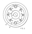
- a ring insert 5 is inserted into the inner cone 3 and screwed into screws 6 (FIG. 2) in threaded holes 6 indicated by dashed lines.
- An insert spindle 10 is inserted into the ring insert 5 about the spindle axis 4 and supported by means of slide bearings 7 and roller bearings 8 and 9. This has a much lower moment of inertia than the spindle 1 in which it is mounted.
- the roller bearing 8 is fastened by screw rings 34, which are screwed onto the insert spindle 10 and secured.
- coaxial bores 12 and 13 are provided in the insert spindle 10 as well as in the ring insert 5 in relation to an axis 11.
- a bolt 14 extends into both bores 12 and 13.
- a section 15 of the bolt 14 has the same outside diameter as the bore 12.
- a section 16 has a significantly smaller diameter than the bore 13.
- a sleeve 17 is inserted into the bore 13, the inner surface 18 of which is slightly conical.
- Section 16 of the bolt 14 and the inner surface 18 of the sleeve 17 is arranged as an elastic element, an elastic ring body 19 which is fastened on the section 16 of the bolt 14 with a snap ring 20 and a washer 21.
- a cover plate 22 protects these elements against contamination.
- the section 15 of the bolt 14 has a threaded bore 23 which is concentric with the axis 11.
- the bore 12 is delimited on the end facing away from the bore 13 by a web 24, which in turn has a through bore 25 for a screw 26 coaxial with the axis 11. With the screw 26 a nut 27 is provided in the bore 12.
- the ring insert 5 has a further bore 13 of the same design in FIG. 1 at the bottom with a sleeve 17.
- a further bore 28 runs coaxially in the insert spindle 5, in which a bolt 29 is fastened, which extends into the bore 13, but has a diameter that is smaller than the diameter of the inner surface 18 of the sleeve 17.
- a ring 30 comprises the ring insert 5 on the outside and extends beyond it to an end face 31 of the insert spindle 10. Lip seals 32 and labyrinth seals 33 are provided between insert spindle 10 and ring 30 in a known manner, for protection against contamination.
- FIG. 2 shows the ring 30, the insert spindle 10 with a through bore 35 as well as the bolt 29 and the screw 26.
- Through bores 36 in the insert spindle 10 allow the ring insert 5, not shown in more detail, to be fastened or loosened by means of the threaded holes 6 screws engaging in spindle 1 6.
- a clamping device for holding a gear to be lapped is placed on the insert spindle 10.
- An annular recess 38 is provided for centering this clamping device.
- the insert spindle 10 mounted in the direction of rotation via the elastic element (here ring body 19) can adapt much better to the vibrations caused by the meshing of the two gear wheels due to its substantially lower moment of inertia.
- the bolt 14 with the ring body 19 can be pushed more or less far into the sleeve 17, so that the ring body 19 is more or less compressed by the conical inner surface 18. So the elasticity of the elastic element can be adjusted depending on the mass of the gear to be lapped.
- the spindle insert is preferably inserted into the brake spindle of the lapping machine.
Landscapes
- Engineering & Computer Science (AREA)
- Mechanical Engineering (AREA)
- Finish Polishing, Edge Sharpening, And Grinding By Specific Grinding Devices (AREA)
- Turning (AREA)
Applications Claiming Priority (2)
| Application Number | Priority Date | Filing Date | Title |
|---|---|---|---|
| CH193081 | 1981-03-23 | ||
| CH1930/81 | 1981-03-23 |
Publications (1)
| Publication Number | Publication Date |
|---|---|
| EP0061086A1 true EP0061086A1 (fr) | 1982-09-29 |
Family
ID=4221915
Family Applications (1)
| Application Number | Title | Priority Date | Filing Date |
|---|---|---|---|
| EP82101990A Withdrawn EP0061086A1 (fr) | 1981-03-23 | 1982-03-12 | Elément rapporté d'une broche |
Country Status (5)
| Country | Link |
|---|---|
| EP (1) | EP0061086A1 (fr) |
| JP (1) | JPS57168829A (fr) |
| AR (1) | AR228304A1 (fr) |
| AU (1) | AU8177082A (fr) |
| BR (1) | BR8201583A (fr) |
Cited By (4)
| Publication number | Priority date | Publication date | Assignee | Title |
|---|---|---|---|---|
| EP0154277A1 (fr) * | 1984-02-28 | 1985-09-11 | I.ME.T. S.p.A. | Dispositif d'entraînement pour une machine-outil rotative, en particulier pour une scie |
| WO2001043908A1 (fr) * | 1999-12-17 | 2001-06-21 | The Gleason Works | Broche pour machine-outil |
| EP1649972A1 (fr) * | 2004-10-21 | 2006-04-26 | Mei s.r.l. | Broche auto-ajustable avec connexion élastique entre ses deux arbres |
| US8795028B2 (en) | 2004-10-04 | 2014-08-05 | The Gleason Works | Magnetic spindle for machine tool |
Citations (7)
| Publication number | Priority date | Publication date | Assignee | Title |
|---|---|---|---|---|
| GB425539A (en) * | 1933-07-17 | 1935-03-18 | Fred Badcock | Improvements in or relating to vibration dampening devices |
| US2381488A (en) * | 1942-04-01 | 1945-08-07 | Ex Cell O Corp | Rotary spindle drive |
| US2596821A (en) * | 1949-03-18 | 1952-05-13 | Gen Motors Corp | Antichatter floating toolholder |
| DE915291C (de) * | 1951-10-28 | 1954-07-19 | Heidenreich & Harbeck Gmbh | Zweifach gelagerte Arbeitsspindel fuer Werkzeugmaschinen, insbesondere Drehbaenke |
| FR1406868A (fr) * | 1963-09-07 | 1965-07-23 | Karl Hueller G M B H | Dispositif d'amortissement pour outils ou leurs supports et pour pièces usinées ouleurs supports |
| CH411527A (de) * | 1962-03-08 | 1966-04-15 | Klingelnberg Soehne Ferd | Maschine zum Läppen von Zahnrädern |
| FR2190559A1 (fr) * | 1972-06-26 | 1974-02-01 | Gleason Works |
-
1982
- 1982-03-05 AR AR28864782A patent/AR228304A1/es active
- 1982-03-12 EP EP82101990A patent/EP0061086A1/fr not_active Withdrawn
- 1982-03-22 AU AU81770/82A patent/AU8177082A/en not_active Abandoned
- 1982-03-22 BR BR8201583A patent/BR8201583A/pt unknown
- 1982-03-23 JP JP4475982A patent/JPS57168829A/ja active Pending
Patent Citations (7)
| Publication number | Priority date | Publication date | Assignee | Title |
|---|---|---|---|---|
| GB425539A (en) * | 1933-07-17 | 1935-03-18 | Fred Badcock | Improvements in or relating to vibration dampening devices |
| US2381488A (en) * | 1942-04-01 | 1945-08-07 | Ex Cell O Corp | Rotary spindle drive |
| US2596821A (en) * | 1949-03-18 | 1952-05-13 | Gen Motors Corp | Antichatter floating toolholder |
| DE915291C (de) * | 1951-10-28 | 1954-07-19 | Heidenreich & Harbeck Gmbh | Zweifach gelagerte Arbeitsspindel fuer Werkzeugmaschinen, insbesondere Drehbaenke |
| CH411527A (de) * | 1962-03-08 | 1966-04-15 | Klingelnberg Soehne Ferd | Maschine zum Läppen von Zahnrädern |
| FR1406868A (fr) * | 1963-09-07 | 1965-07-23 | Karl Hueller G M B H | Dispositif d'amortissement pour outils ou leurs supports et pour pièces usinées ouleurs supports |
| FR2190559A1 (fr) * | 1972-06-26 | 1974-02-01 | Gleason Works |
Cited By (5)
| Publication number | Priority date | Publication date | Assignee | Title |
|---|---|---|---|---|
| EP0154277A1 (fr) * | 1984-02-28 | 1985-09-11 | I.ME.T. S.p.A. | Dispositif d'entraînement pour une machine-outil rotative, en particulier pour une scie |
| WO2001043908A1 (fr) * | 1999-12-17 | 2001-06-21 | The Gleason Works | Broche pour machine-outil |
| US6481508B2 (en) | 1999-12-17 | 2002-11-19 | The Gleason Works | Spindle for machine tool |
| US8795028B2 (en) | 2004-10-04 | 2014-08-05 | The Gleason Works | Magnetic spindle for machine tool |
| EP1649972A1 (fr) * | 2004-10-21 | 2006-04-26 | Mei s.r.l. | Broche auto-ajustable avec connexion élastique entre ses deux arbres |
Also Published As
| Publication number | Publication date |
|---|---|
| BR8201583A (pt) | 1983-02-08 |
| AR228304A1 (es) | 1983-02-15 |
| AU8177082A (en) | 1982-11-04 |
| JPS57168829A (en) | 1982-10-18 |
Similar Documents
| Publication | Publication Date | Title |
|---|---|---|
| DE10053183B4 (de) | Vorrichtung für die automatische Steuerung des Abstands zwischen Zahnrädern | |
| DE2919744A1 (de) | Drehmomentabhaengige drehzahlumschalteinrichtung fuer motorschrauber | |
| DE60105247T2 (de) | Drehtischvorrichtung | |
| DE3732817A1 (de) | Kraftfahrzeug-steuersaeulenmechanismus | |
| EP0641621B1 (fr) | Dispositif d'entraînement rotatif | |
| EP0911116B1 (fr) | Article de meulage et dispositif de fixation | |
| DE2220790B2 (de) | Einstellbarer Tiefenanschlag für ein tragbares kraftangetriebenes Werkzeug | |
| DE2007849C3 (de) | Vorrichtung zum kraftschlüssigen Befestigen eines Zahnrades auf einer keillosen Welle | |
| DE2751720C2 (de) | Montagevorrichtung für Wälzlager | |
| DE3613987A1 (de) | Vorrichtung zum loesbaren befestigen einer schleifscheibe | |
| DE3345800C2 (de) | Vorrichtung zum Herstellen und Bearbeiten von Zahnrädern | |
| EP0061086A1 (fr) | Elément rapporté d'une broche | |
| DE1139720B (de) | Vorrichtung zum Feinbearbeiten von Zahnraedern mit einem Schabrad oder mit einem anderen zahnrad-foermigen Werkzeug | |
| DE1440268B2 (de) | Verfahren und Maschine zum Bearbeiten von Drehflächen durch Elektroerosion | |
| DE10322181B4 (de) | Abrichtwerkzeug zum Abrichten einer Schleifschnecke | |
| DE2626912A1 (de) | Maschine zur bearbeitung von werkstuecken | |
| DE19740208C2 (de) | Antriebsvorrichtung für mehrere Aggregate einer Drehmaschine | |
| DE3344548A1 (de) | Verfahren und vorrichtung zum herstellen und bearbeiten von zahnraedern | |
| CH673102A5 (fr) | ||
| DE2063074C3 (de) | Unterflur-Radsatzdrehmaschine für das Pr,ofildrehen von Radsätzen von Schie nenf ahrzeuge n | |
| DE2150558C3 (de) | Bohrkopf | |
| DE3816307C1 (en) | Feed device for an apparatus for the rotary machining of a workpiece | |
| DE2030620B2 (de) | Vorrichtung zur Sicherung einer Schleifscheibe gegen Überschreiten ihrer maximal zulässigen Umfangsgeschwindigkeit | |
| DE10137625B4 (de) | Schnellspannmutter | |
| CH683790A5 (de) | Verbindungsgerät, insbesondere eine Spannvorrichtung. |
Legal Events
| Date | Code | Title | Description |
|---|---|---|---|
| PUAI | Public reference made under article 153(3) epc to a published international application that has entered the european phase |
Free format text: ORIGINAL CODE: 0009012 |
|
| AK | Designated contracting states |
Designated state(s): CH DE FR GB IT SE |
|
| 17P | Request for examination filed |
Effective date: 19821220 |
|
| STAA | Information on the status of an ep patent application or granted ep patent |
Free format text: STATUS: THE APPLICATION HAS BEEN WITHDRAWN |
|
| 18W | Application withdrawn |
Withdrawal date: 19831014 |
|
| RIN1 | Information on inventor provided before grant (corrected) |
Inventor name: KOTTHAUS, ERICH Inventor name: KONERSMANN, ERHARD |