EP0060827A1 - Cooling means for the cutter of a coal cutting machine - Google Patents
Cooling means for the cutter of a coal cutting machine Download PDFInfo
- Publication number
- EP0060827A1 EP0060827A1 EP82890023A EP82890023A EP0060827A1 EP 0060827 A1 EP0060827 A1 EP 0060827A1 EP 82890023 A EP82890023 A EP 82890023A EP 82890023 A EP82890023 A EP 82890023A EP 0060827 A1 EP0060827 A1 EP 0060827A1
- Authority
- EP
- European Patent Office
- Prior art keywords
- chisel
- valve
- shut
- shaft
- coupling element
- Prior art date
- Legal status (The legal status is an assumption and is not a legal conclusion. Google has not performed a legal analysis and makes no representation as to the accuracy of the status listed.)
- Granted
Links
- 238000005520 cutting process Methods 0.000 title claims abstract description 24
- 238000001816 cooling Methods 0.000 title claims abstract description 4
- 239000003245 coal Substances 0.000 title 1
- 230000008878 coupling Effects 0.000 claims abstract description 15
- 238000010168 coupling process Methods 0.000 claims abstract description 15
- 238000005859 coupling reaction Methods 0.000 claims abstract description 15
- 239000000498 cooling water Substances 0.000 claims abstract description 14
- XLYOFNOQVPJJNP-UHFFFAOYSA-N water Substances O XLYOFNOQVPJJNP-UHFFFAOYSA-N 0.000 claims abstract description 12
- 238000007789 sealing Methods 0.000 claims description 4
- 239000000356 contaminant Substances 0.000 description 3
- 238000005507 spraying Methods 0.000 description 3
- 239000000428 dust Substances 0.000 description 2
- 238000005553 drilling Methods 0.000 description 1
- 238000011010 flushing procedure Methods 0.000 description 1
- 238000003754 machining Methods 0.000 description 1
- 239000011435 rock Substances 0.000 description 1
Images
Classifications
-
- E—FIXED CONSTRUCTIONS
- E21—EARTH OR ROCK DRILLING; MINING
- E21C—MINING OR QUARRYING
- E21C35/00—Details of, or accessories for, machines for slitting or completely freeing the mineral from the seam, not provided for in groups E21C25/00 - E21C33/00, E21C37/00 or E21C39/00
- E21C35/18—Mining picks; Holders therefor
- E21C35/187—Mining picks; Holders therefor with arrangement of fluid-spraying nozzles
Definitions
- the invention relates to a device for cooling the chisel of a cutting machine with a nozzle arranged in the area of the chisel for the cooling water to be sprayed under pressure, to which the water supply can be shut off by a shut-off valve, the chisel on the chisel holder against the force of a spring and the hydraulic pressure of the cooling water axially ver limited by the average pressure - is mounted slidably and the stop valve is coupled with the bit by a coupling member such that it opens at a sliding movement of the bit in direction of the cutting pressure.
- a device enables the spraying of the cooling water from the nozzle to be restricted to the period during which the chisel in question attacks the rock.
- the spraying of the cooling water is interrupted during the period in which the chisel in question is not in operation and therefore a considerable saving in cooling water is made possible.
- This not only has the advantage of saving water, but above all also the advantage that the sole is not excessively softened by water spraying out.
- the chisel shaft is displaceably mounted in the chisel holder against a spring force and engages with a collar on the coupling element which actuates the shut-off valve.
- This coupling element must be arranged on the outside of the chisel holder and is therefore exposed to damage during cutting operation.
- the invention now aims to design the actuation of the shut-off valve so that it is reliable and secured against damage.
- the invention consists essentially in the fact that the chisel is cap-shaped in a manner known per se and encloses a chisel shank that can be inserted into the chisel holder, that the cap-shaped chisel is mounted axially displaceably on the shank is and that the shut-off valve and the coupling element is arranged in the chisel shaft.
- Cap-shaped chisels which overlap the chisel shaft immovably inserted in the chisel holder and are rotatably arranged thereon are known.
- the arrangement is such that the shut-off valve closes counter to the direction of the cutting pressure and that the chisel shaft has a central bore in which a plunger acting on the movable valve body and possibly integrally formed therewith is axially displaceable, which forms the coupling element.
- the movable valve body is expediently formed by a valve cone, but can also be formed by a ball.
- this movable valve body it is also possible to design this movable valve body as a slide, which is moved into the open position by the coupling element when the cutting pressure occurs in a slide mirror.
- the design is expediently such that the movable valve body opens in the direction of the cutting pressure and the spring which loads the chisel against the cutting pressure is formed by the spring acting on the movable valve body.
- a spring is sufficient, which both holds the valve in the closed position and loads the chisel against the cutting pressure.
- the valve housing is preferably tubular and inserted in a central bore of the chisel shank. This enables a simple design of the chisel shank, the machining of the chisel shank being restricted to simple turning and drilling work.
- the cap-shaped chisel should be rotatably mounted on the chisel shaft and it is essential that the chisel can actually twist during operation and is not blocked by dust and contaminants entering the gap between the chisel shaft and the chisel, since in this case the cutting accuracy of the chisel in Question would be asked. This inevitably results in a certain, albeit small, gap between the inner wall of the cap-shaped chisel and the chisel shaft, and there is a risk that dust and other contaminants which hinder the rotary movement of the chisel will accumulate in this gap.
- the plunger is expediently leaky in the bore of the chisel shaft and in a guide bore of the valve housing.
- This enables water to escape from the valve along the tappet to the annular gap between the chisel and the chisel shaft, and this annular gap is thereby rinsed, so that contaminants which have penetrated into this annular gap are discharged to the outside.
- This ensures the easy rotation of the chisel on the chisel shaft.
- a slotted ring in particular a sealing ring, is inserted between the tappet and the guide bore of the valve housing for this purpose, the slot of which forms a passage cross section for water. By dimensioning this slot, the water outlet can be limited to the minimum required for flushing the annular gap.
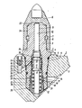
- the invention is illustrated using an exemplary embodiment which shows an axial section through the chisel and the chisel shank and through the chisel holder shows.
- the surface of the chisel holder 1 is welded to the cutting head 2.
- a chisel shank 3 is inserted into the chisel holder 1 and is screwed in by means of a thread 4.
- 5 is a seal.
- a cap-shaped chisel 6 is rotatably mounted on the chisel shaft 3.
- the annular groove 7 has a greater axial extent than the inserted circlip, so that the chisel 6 is axially displaceably mounted on the chisel shaft.
- a plunger 10 is guided axially displaceably, which consists of one piece with a valve cone 11.
- the valve cone 11 is pressed onto the valve seat 13 by a spring 12.
- This spring also loads the plunger 6 in the direction opposite to the cutting pressure via the plunger 10, so that in the idle state the chisel 6 is lifted from a shoulder 14 of the chisel shaft by a dimension a.
- the valve 11 is lifted from the seat against the force of the spring 12 and the chisel 6 sits on the shoulder 14.
- the cooling water passes through bores 17 into an annular space 18 and from here through bores 19 of a tubular valve housing 20 into the space 21 of the valve housing 20.
- 22 is an annular filter, which extends around the valve housing 20 in the region of the bores 19 is laid around.
- a sealing ring 32 is inserted into a groove 31 in the plunger 10.
- This sealing ring which consists for example of hard plastic, is slotted on its circumference, so that a small amount of water can pass out of the space 23.
- the plunger 10 is guided in the bore 9 of the chisel shank 3 so that a slight amount of water can pass into the space 33 between the chisel shank 3 and the chisel 6 via the gap in the seal 32.
- This water can escape through the annular gap 34 between the chisel shaft 3 and the chisel 6 at 35, so that this annular gap 34 is rinsed.
- valve housing 20 is screwed into the chisel shaft 3.
Landscapes
- Engineering & Computer Science (AREA)
- Mining & Mineral Resources (AREA)
- Geology (AREA)
- Life Sciences & Earth Sciences (AREA)
- General Life Sciences & Earth Sciences (AREA)
- Geochemistry & Mineralogy (AREA)
- Mechanical Engineering (AREA)
- Lift Valve (AREA)
- Drilling And Exploitation, And Mining Machines And Methods (AREA)
- Auxiliary Devices For Machine Tools (AREA)
- Sampling And Sample Adjustment (AREA)
- Drilling And Boring (AREA)
- Earth Drilling (AREA)
- Sawing (AREA)
- Percussive Tools And Related Accessories (AREA)
Abstract
Die Erfindung bezieht sich auf eine Einrichtung zum Kühlen der Meissel einer Schrämmaschine mit einer im Bereich des Meissels angeordneten Düse für das unter Druck auszuspritzende Kühlwasser, zu welcher die Wasserzufuhr durch ein Absperrventil absperrbar ist, wobei der Meissel am Meisselhalter entgegen der Kraft einer Feder und des hydraulischen Druckes des Kühlwassers durch den Schnittdruck begrenzt axial verschiebbar gelagert ist und das Absperrventil mit dem Meissel durch ein Kuppelglied derart gekuppelt ist, dass es bei einer Verschiebebewegung des Meissels in Richtung des Schnittdrukkes öffnet. Hiebei ist der Meissel (6) kappenförmig ausgebildet, umschliesst einen in den Meisselhalter (1) einsetzbaren Meisselschaft (3) und ist am Meisselschaft (3) axial verschiebbar gelagert, wobei das Absperrventil (11) und das Kuppelglied (10) im Meisselschaft (3) angeordnet ist, Das Kuppelglied ist hiebei von einem auf den Ventilkörper (11) wirkenden Stössel (10) gebildet, der in einer zentralen Bohrung (9) des Meisselschaftes geführt ist, wobei das Absperrventil (11) entgegen der Wirkung des Schnittdruckes schliesst und durch den Stössel (10) in Richtung des Schnittdruckes geöffnet wird.The invention relates to a device for cooling the chisel of a cutting machine with a nozzle arranged in the area of the chisel for the cooling water to be sprayed out under pressure, to which the water supply can be shut off by a shut-off valve, the chisel on the chisel holder against the force of a spring and the hydraulic pressure of the cooling water is axially displaceably limited by the cutting pressure and the shut-off valve is coupled to the chisel by a coupling element in such a way that it opens when the chisel is moved in the direction of the cutting pressure. The chisel (6) is in the form of a cap, encloses a chisel shaft (3) which can be inserted into the chisel holder (1) and is axially displaceably mounted on the chisel shaft (3), the shut-off valve (11) and the coupling element (10) in the chisel shaft (3 ) is arranged, the coupling element is hereby formed by a plunger (10) acting on the valve body (11), which is guided in a central bore (9) of the chisel shaft, the shut-off valve (11) closing against and through the action of the cutting pressure the plunger (10) is opened in the direction of the cutting pressure.
Description
Die Erfindung bezieht sich auf eine Einrichtung zum Kühlen der Meißel einer Schrämmaschine mit einer im Bereich des Meißels angeordneten Düse für das unter Druck auszuspritzende Kühlwasser, zu welcher die Wasserzufuhr durch ein Absperrventil absperrbar ist, wobei der Meißel am Meißelhalter entgegen der Kraft einer Feder und des hydraulischen Druckes des Kühlwassers durch den Schnittdruck begrenzt axial ver- schiebbar gelagert ist und das Absperrventil mit dem Meißel durch ein Kuppelglied derart gekuppelt ist, daß es bei einer Verschiebebewegung des Meißels in Richtung des Schnittdruckes öffnet. Eine solche Einrichtung ermöglicht das Ausspritzen des Kühlwassers aus der Düse auf denjenigen Zeitraum zu beschränken, während welchem der betreffende Meißel am Gestein angreift. Die Ausspritzung des Kühlwassers ist während des Zeitraumes, während welchem der betreffende Meißel nicht in Tätigkeit ist, unterbrochen und es wird daher eine beträchtliche Einsparung an Kühlwasser ermöglicht. Dies hat nicht nur den Vorteil einer Wassereinsparung, sondern vor allem auch den Vorteil, daß die Sohle nicht in übermäßiger Weise durch ausspritzendes Wasser aufgeweicht wird. Bei einer bekannten Einrichtung dieser Art ist der Meißelschaft entgegen einer Federkraft verschiebbar im Meißelhalter gelagert und greift mit einem Bund an dem das Absperrventil betätigenden Kuppelglied an. Dieses Kuppelglied muß außen am Meißelhalter angeordnet sein und ist daher Beschädigungen beim Schrämbetrieb ausgesetzt.The invention relates to a device for cooling the chisel of a cutting machine with a nozzle arranged in the area of the chisel for the cooling water to be sprayed under pressure, to which the water supply can be shut off by a shut-off valve, the chisel on the chisel holder against the force of a spring and the hydraulic pressure of the cooling water axially ver limited by the average pressure - is mounted slidably and the stop valve is coupled with the bit by a coupling member such that it opens at a sliding movement of the bit in direction of the cutting pressure. Such a device enables the spraying of the cooling water from the nozzle to be restricted to the period during which the chisel in question attacks the rock. The spraying of the cooling water is interrupted during the period in which the chisel in question is not in operation and therefore a considerable saving in cooling water is made possible. This not only has the advantage of saving water, but above all also the advantage that the sole is not excessively softened by water spraying out. In a known device of this type, the chisel shaft is displaceably mounted in the chisel holder against a spring force and engages with a collar on the coupling element which actuates the shut-off valve. This coupling element must be arranged on the outside of the chisel holder and is therefore exposed to damage during cutting operation.
Die Erfindung zielt nun darauf ab, die Betätigung des Absperrventiles so zu gestalten, daß sie betriebssicher und gegen Beschädigung gesichert ist. Die Erfindung besteht hiebei im wesentlichen darin, daß der Meißel in an sich bekannter Weise kappenförmig ausgebildet ist und einen in den Meißelhalter einsetzbaren Meißelschaft umschließt, daß der kappenförmige Meißel am Schaft axial verschiebbar gelagert ist und daß das Absperrventil und das Kuppelglied im Meißelschaft angeordnet ist. Kappenförmige Meißel, welche den im Meißelhalter unbeweglich eingesetzten Meißelschaft übergreifen und auf diesem verdrehbar angeordnet sind, sind bekannt. Dadurch, daß nun das Kuppelglied in diesem Meißelschaft angeordnet ist, ist dieses Kuppelglied durch den kappenförmigen Meißel gegen Verschmutzung und gegen Beschädigungen geschützt. Dadurch, daß das Absperrventil selbst auch im Meißelschaft angeordnet ist, wird eine konstruktiv einfache Ausbildung geschaffen, da nun alle komplizierten Teile in dem Meißelschaft angeordnet sind, welcher durch den kappenförmigen Meißel geschützt ist. Es ist nun nur erforderlich, die Führungsbohrungen durch das Kühlwasser in die Düse im Meißelhalter anzuordnen. Gemäß einer bevorzugten Ausführungsform der Erfindung ist die Anordnung so getroffen, daß das Absperrventil entgegen der Richtung des Schnittdruckes schließt und daß der Meißelschaft eine zentrale Bohrung aufweist, in welcher ein auf den beweglichen Ventilkörper wirkender, gegebenenfalls mit diesem einteilig ausgebildeter Stössel axial verschiebbar geführt ist, welcher das Kuppelglied bildet. Auf diese Art ist eine einfache Ausbildung des Kuppelgliedes ermöglicht. Der bewegliche Ventilkörper ist zweckmäßig von einem Ventilkegel gebildet, kann aber auch von einer Kugel gebildet sein. Letzten Endes ist es auch möglich, diesen beweglichen Ventilkörper als Schieber auszubilden, der durch das Kuppelglied bei Auftreten des Schnittdruckes in einem Schieberspiegel in die Offenstellung verschoben wird.The invention now aims to design the actuation of the shut-off valve so that it is reliable and secured against damage. The invention consists essentially in the fact that the chisel is cap-shaped in a manner known per se and encloses a chisel shank that can be inserted into the chisel holder, that the cap-shaped chisel is mounted axially displaceably on the shank is and that the shut-off valve and the coupling element is arranged in the chisel shaft. Cap-shaped chisels, which overlap the chisel shaft immovably inserted in the chisel holder and are rotatably arranged thereon are known. Characterized in that the coupling element is now arranged in this chisel shaft, this coupling element is protected against dirt and damage by the cap-shaped chisel. The fact that the shut-off valve itself is also arranged in the chisel shaft creates a structurally simple design since all the complicated parts are now arranged in the chisel shaft, which is protected by the cap-shaped chisel. It is now only necessary to arrange the guide holes through the cooling water in the nozzle in the chisel holder. According to a preferred embodiment of the invention, the arrangement is such that the shut-off valve closes counter to the direction of the cutting pressure and that the chisel shaft has a central bore in which a plunger acting on the movable valve body and possibly integrally formed therewith is axially displaceable, which forms the coupling element. In this way, a simple design of the coupling element is made possible. The movable valve body is expediently formed by a valve cone, but can also be formed by a ball. Ultimately, it is also possible to design this movable valve body as a slide, which is moved into the open position by the coupling element when the cutting pressure occurs in a slide mirror.
Zweckmäßig ist gemäß der Erfindung die Ausbildung so getroffen, daß der bewegliche Ventilkörper in Richtung des Schnittdruckes öffnet und die den Meißel entgegen dem Schnittdruck belastende Feder von der auf den beweglichen Ventilkörper wirkenden Feder gebildet ist. Hiebei genügt eine Feder, welche sowohl das Ventil in Schließstellung hält als auch den Meißel entgegen dem Schnittdruck belastet. Vorzugsweise ist gemäß der Erfindung das.. Ventilgehäuse rohrförmig ausgebildet und in eine zentrale Bohrung des Meißelschaftes eingesetzt. Dies ermöglicht eine einfache Ausbildung des Meißelschaftes, wobei die Bearbeitung des Meißelschaftes auf einfache Dreh-und Bohrarbeiten beschränkt ist.According to the invention, the design is expediently such that the movable valve body opens in the direction of the cutting pressure and the spring which loads the chisel against the cutting pressure is formed by the spring acting on the movable valve body. A spring is sufficient, which both holds the valve in the closed position and loads the chisel against the cutting pressure. According to the invention, the valve housing is preferably tubular and inserted in a central bore of the chisel shank. This enables a simple design of the chisel shank, the machining of the chisel shank being restricted to simple turning and drilling work.
Der kappenförmige Meißel soll am Meißelschaft drehbar gelagert sein und es ist wesentlich, daß der Meißel sich tatsächlich während des Betriebes verdrehen kann und nicht durch in den Spalt zwischen Meißelschaft und Meißel eindringenden Staub und Verunreinigungen blockiert wird, da in diesem Fall die Schnittgenauigkeit des Meißels in Frage gestellt wäre. Dies hat zwangsläufig zur Folge, daß ein gewisser, wenn auch kleiner Spalt zwischen der Innenwandung des kappenförmigen Meißels und dem Meißelschaft besteht, und es besteht die Gefahr, daß in diesem Spalt sich Staub und andere Verunreinigungen, welche die Drehbewegung des Meißels behindern, ansammelt. Um dies zu vermeiden, ist zweckmäßig gemäß der Erfindung der Stössel in der Bohrung des Meißelschaftes und in einer Führungsbohrung des Ventilgehäuses undicht geführt. Damit wird ein Wasseraustritt aus dem Ventil entlang dem Stössel zu dem Ringspalt zwischen Meißel und Meißelschaft ermöglicht und es wird dadurch dieser Ringspalt gespült, so daß in diesen Ringspalt eingedrungene Verunreinigungen nach außen abgeführt werden. Damit wird die leichte Drehbarkeit des Meißels am Meißelschaft gewährleistet. Gemäß der Erfindung ist zu diesem Zwecke vorzugsweise zwischen dem Stössel und der Führungsbohrung des Ventilgehäuses ein geschlitzter Ring, insbesondere Dichtungsring, eingesetzt, dessen Schlitz einen Durchtrittsquerschnitt für Wasser bildet. Durch die Bemessung dieses Schlitzes kann der Wasseraustritt für das für die Spülung des Ringspaltes erforderliche Minimum beschränkt werden.The cap-shaped chisel should be rotatably mounted on the chisel shaft and it is essential that the chisel can actually twist during operation and is not blocked by dust and contaminants entering the gap between the chisel shaft and the chisel, since in this case the cutting accuracy of the chisel in Question would be asked. This inevitably results in a certain, albeit small, gap between the inner wall of the cap-shaped chisel and the chisel shaft, and there is a risk that dust and other contaminants which hinder the rotary movement of the chisel will accumulate in this gap. In order to avoid this, according to the invention, the plunger is expediently leaky in the bore of the chisel shaft and in a guide bore of the valve housing. This enables water to escape from the valve along the tappet to the annular gap between the chisel and the chisel shaft, and this annular gap is thereby rinsed, so that contaminants which have penetrated into this annular gap are discharged to the outside. This ensures the easy rotation of the chisel on the chisel shaft. According to the invention, a slotted ring, in particular a sealing ring, is inserted between the tappet and the guide bore of the valve housing for this purpose, the slot of which forms a passage cross section for water. By dimensioning this slot, the water outlet can be limited to the minimum required for flushing the annular gap.
In der Zeichnung ist die Erfindung anhand eines Ausführungsbeispieles dargestellt, welches einen Axialschnitt durch den Meißel und den Meißelschaft sowie durch den Meißelhalter zeigt.In the drawing, the invention is illustrated using an exemplary embodiment which shows an axial section through the chisel and the chisel shank and through the chisel holder shows.
Der Meißelhalter 1 ist mit seiner Fläche 2 mit dem Schrämkopf verschweißt. In dem Meißelhalter 1 ist ein Meißelschaft 3 eingesetzt, und zwar mittels eines Gewindes 4 eingeschraubt. 5 ist eine Dichtung. Auf dem Meißelschaft 3 ist ein kappenförmiger Meißel 6 drehbar gelagert. Durch eine Ringnut 7 im Meißelschaft und eine Ringnut 8 im kappenförmigen Mantel des Meißels 6 ist ein Ringraum geschaffen, in welchen ein Sicherungsring eingelegt wird. Die Ringnut 7 hat eine größere Axialerstreckung als der eingelegte Sicherungsring, so daß der Meißel 6 auf dem Meißelschaft axial verschiebbar gelagert ist.The surface of the chisel holder 1 is welded to the
In einer zentralen Bohrung 9 des Meißelschaftes ist ein Stössel 10 axial verschiebbar geführt, welcher mit einem Ventilkegel 11 aus einem Stück besteht. Durch eine Feder 12 wird der Ventilkegel 11 auf den Ventilsitz 13 gedrückt. Diese Feder belastet gleichzeitig auch über den Stössel 10 den Meißel 6 in Richtung entgegen dem Schnittdruck, so daß im Ruhezustand der Meißel 6 von einer Schulter 14 des Meißelschaftes um ein Maß a abgehoben ist. Sobald der Schnittdruck auftritt, wird das Ventil 11 entgegen der Kraft der Feder 12 vom Sitz abgehoben und der Meißel 6 sitzt auf der Schulter 14 auf.In a
15 ist eine im Meißelschaft angeordnete Bohrung für die Zuführung des Kühlwassers. über eine Ringnut 16 im Schaft gelangt das Kühlwasser durch Bohrungen 17 in einen Ringraum 18 und von hier durch Bohrungen 19 eines rohrförmigen Ventilgehäuses 20 in den Raum 21 des Ventilgehäuses 20. 22 ist ein ringförmiger Filter, welcher um das Ventilgehäuse 20 im Bereich der Bohrungen 19 herumgelegt ist. Bei abgehobenem Ventilkegel 11 gelangt nun* das Kühlwasser in den Raum 23 hinter den Ventilkegel 11 und von hier aus über Bohrungen 24 und eine Ringnut 25 zu einer Bohrung 26 im Meißelschaft 3, von wo aus das Kühlwasser über eine Ringnut 27 und Bohrungen 28, 29 zu einer Düse 30 gelangt.15 is a bore in the chisel shaft for supplying the cooling water. Via an
In eine Nut 31 des Stössels 10 ist ein Dichtungsring 32 eingelegt. Dieser Dichtungsring, welcher beispielsweise aus hartem Kunststoff besteht, ist an seinem Umfang geschlitzt, so daß eine geringfügige Menge Wasser aus dem Raum 23 durchtreten kann. Der Stössel 10 ist in der Bohrung 9 des Meißelschaftes 3 undicht geführt, so daß über den Spalt in der Dichtung 32 eine geringfügige Menge von Wasser in den Raum 33 zwischen Meißelschaft 3 und Meißel 6 übertreten kann. Dieses Wasser kann über den Ringspalt 34 zwischen Meißelschaft 3 und Meißel 6 bei 35 austreten, so daß dieser Ringspalt 34 gespült wird.A sealing ring 32 is inserted into a groove 31 in the
36 ist ein Gewinde, mittels welchem das Ventilgehäuse 20 in den Meißelschaft 3 eingeschraubt ist.36 is a thread by means of which the
Claims (6)
Applications Claiming Priority (2)
| Application Number | Priority Date | Filing Date | Title |
|---|---|---|---|
| AT0113581A AT369859B (en) | 1981-03-12 | 1981-03-12 | DEVICE FOR COOLING THE CHISELS OF A BREWING MACHINE |
| AT1135/81 | 1981-03-12 |
Publications (2)
| Publication Number | Publication Date |
|---|---|
| EP0060827A1 true EP0060827A1 (en) | 1982-09-22 |
| EP0060827B1 EP0060827B1 (en) | 1984-05-09 |
Family
ID=3507354
Family Applications (1)
| Application Number | Title | Priority Date | Filing Date |
|---|---|---|---|
| EP82890023A Expired EP0060827B1 (en) | 1981-03-12 | 1982-02-16 | Cooling means for the cutter of a coal cutting machine |
Country Status (16)
| Country | Link |
|---|---|
| US (1) | US4456306A (en) |
| EP (1) | EP0060827B1 (en) |
| JP (1) | JPS57163040A (en) |
| AT (1) | AT369859B (en) |
| AU (1) | AU547795B2 (en) |
| BR (1) | BR8201281A (en) |
| CA (1) | CA1176665A (en) |
| DE (1) | DE3260140D1 (en) |
| ES (1) | ES509902A0 (en) |
| IN (1) | IN155702B (en) |
| MX (1) | MX6604E (en) |
| PL (1) | PL138252B1 (en) |
| RO (1) | RO84541B (en) |
| SU (1) | SU1269743A3 (en) |
| YU (1) | YU40082A (en) |
| ZA (1) | ZA821221B (en) |
Cited By (13)
| Publication number | Priority date | Publication date | Assignee | Title |
|---|---|---|---|---|
| GB2127459A (en) * | 1982-09-22 | 1984-04-11 | Bergwerksverband Gmbh | Mining machines |
| EP0111143A2 (en) * | 1982-11-13 | 1984-06-20 | VOEST-ALPINE Aktiengesellschaft | Core bit with damped guided cylindrical shank |
| EP0067145B1 (en) * | 1981-06-04 | 1984-07-25 | VOEST-ALPINE Aktiengesellschaft | Cooling device for the tools of a continuous mining machine |
| EP0067144B1 (en) * | 1981-06-04 | 1984-07-25 | VOEST-ALPINE Aktiengesellschaft | Cooling device for the tools of a continuous mining machine |
| GB2135715A (en) * | 1983-03-02 | 1984-09-05 | Padley & Venables Ltd | Water sprayed, mineral mining pick assembly |
| US4488759A (en) * | 1982-03-10 | 1984-12-18 | Santrade Ltd. | Device for supplying fluid to a tool for breaking hard material |
| US4542942A (en) * | 1982-07-06 | 1985-09-24 | Voest-Alpine Aktiengesellschaft | Bit holder equipped with a spraying device |
| FR2571427A1 (en) * | 1984-10-06 | 1986-04-11 | Boart Hwf Gmbh & Co Kg | HAVAGE TOOL, PARTICULARLY FOR MACHINES FOR PATHWAYS |
| EP0125232B1 (en) * | 1983-04-11 | 1986-11-26 | VOEST-ALPINE Aktiengesellschaft | Process for cutting rock, and device for carrying out this process |
| EP0229238A1 (en) * | 1985-12-13 | 1987-07-22 | Boart International Limited | Mining tool for winning minerals, particularly coal |
| US4976496A (en) * | 1988-07-19 | 1990-12-11 | Sandvik Ab | Valve openable in response to displacement of a cutting tool |
| AT227U1 (en) * | 1990-04-05 | 1995-05-26 | Voest Alpine Bergtechnik | SNOW FENCE |
| CN101555792B (en) * | 2009-05-23 | 2011-07-20 | 山东卡特重工有限公司 | Gate-type nozzle of excavator with internal spraying |
Families Citing this family (9)
| Publication number | Priority date | Publication date | Assignee | Title |
|---|---|---|---|---|
| US4664450A (en) * | 1983-03-02 | 1987-05-12 | Padley & Venables Limited | Holder for a pick, and the combination of a pick and holder |
| US4569558A (en) * | 1983-07-25 | 1986-02-11 | The Regents Of The University Of California | Drag bit construction |
| SE452495B (en) * | 1985-06-13 | 1987-11-30 | Sandvik Ab | DEVICE FOR LIQUID SUPPLY TO A TOOL FOR EXCHANGE OF SOLID MATERIAL |
| US4765686A (en) * | 1987-10-01 | 1988-08-23 | Gte Valenite Corporation | Rotatable cutting bit for a mining machine |
| AT389738B (en) * | 1988-04-28 | 1990-01-25 | Voest Alpine Ag | DEVICE FOR INTERMITTENTLY SPRAYING CHISELS OF A SCREW HEAD |
| GB0017470D0 (en) * | 2000-07-18 | 2000-08-30 | Hydra Tools Int Plc | Pick box for housing a mineral cutter pick |
| DE10261646B4 (en) * | 2002-12-27 | 2010-02-25 | Wirtgen Gmbh | Schrämwerkzeug |
| US7234782B2 (en) * | 2005-02-18 | 2007-06-26 | Sandvik Intellectual Property Ab | Tool holder block and sleeve retained therein by interference fit |
| US8215719B2 (en) * | 2009-10-06 | 2012-07-10 | Kennametal Inc. | Rotatable cutting tool with through coolant |
Citations (4)
| Publication number | Priority date | Publication date | Assignee | Title |
|---|---|---|---|---|
| DE1283777B (en) * | 1967-11-22 | 1968-11-28 | Austin Hoy And Company Ltd Sta | Interchangeable chisels with chisel holder and with feeds for liquid |
| DE1998508U (en) * | 1968-05-22 | 1968-12-19 | Heinz Hoetten | DEVICE FOR SPRAYING TRAILERS |
| EP0010534A1 (en) * | 1978-10-19 | 1980-04-30 | VOEST-ALPINE Aktiengesellschaft | Device for cooling the picks of the cutting tools of a cutting machine and the excavation face and for preventing the formation of dust |
| DE2854307A1 (en) * | 1978-12-15 | 1980-07-03 | Kennametal Inc | BRACKET FOR ATTACHING CHISELS, ESPECIALLY ROUNDING CHISELS TO MINING EXTRACTION AND TRACKING MACHINES |
Family Cites Families (1)
| Publication number | Priority date | Publication date | Assignee | Title |
|---|---|---|---|---|
| SU685821A1 (en) * | 1978-06-29 | 1979-09-15 | Копейский Ордена Трудового Красного Знамени Машиностроительный Завод Им. С.М.Кирова | Cutting crown of mine cutter-loader |
-
1981
- 1981-03-12 AT AT0113581A patent/AT369859B/en not_active IP Right Cessation
-
1982
- 1982-02-16 DE DE8282890023T patent/DE3260140D1/en not_active Expired
- 1982-02-16 EP EP82890023A patent/EP0060827B1/en not_active Expired
- 1982-02-20 IN IN199/CAL/82A patent/IN155702B/en unknown
- 1982-02-23 CA CA000396819A patent/CA1176665A/en not_active Expired
- 1982-02-23 AU AU80728/82A patent/AU547795B2/en not_active Ceased
- 1982-02-23 YU YU00400/82A patent/YU40082A/en unknown
- 1982-02-24 ZA ZA821221A patent/ZA821221B/en unknown
- 1982-02-25 SU SU823416190A patent/SU1269743A3/en active
- 1982-02-25 ES ES509902A patent/ES509902A0/en active Granted
- 1982-03-02 US US06/353,936 patent/US4456306A/en not_active Expired - Fee Related
- 1982-03-09 PL PL1982235364A patent/PL138252B1/en unknown
- 1982-03-10 BR BR8201281A patent/BR8201281A/en unknown
- 1982-03-11 RO RO106876A patent/RO84541B/en unknown
- 1982-03-11 JP JP57038838A patent/JPS57163040A/en active Granted
- 1982-03-12 MX MX82101016U patent/MX6604E/en unknown
Patent Citations (4)
| Publication number | Priority date | Publication date | Assignee | Title |
|---|---|---|---|---|
| DE1283777B (en) * | 1967-11-22 | 1968-11-28 | Austin Hoy And Company Ltd Sta | Interchangeable chisels with chisel holder and with feeds for liquid |
| DE1998508U (en) * | 1968-05-22 | 1968-12-19 | Heinz Hoetten | DEVICE FOR SPRAYING TRAILERS |
| EP0010534A1 (en) * | 1978-10-19 | 1980-04-30 | VOEST-ALPINE Aktiengesellschaft | Device for cooling the picks of the cutting tools of a cutting machine and the excavation face and for preventing the formation of dust |
| DE2854307A1 (en) * | 1978-12-15 | 1980-07-03 | Kennametal Inc | BRACKET FOR ATTACHING CHISELS, ESPECIALLY ROUNDING CHISELS TO MINING EXTRACTION AND TRACKING MACHINES |
Cited By (16)
| Publication number | Priority date | Publication date | Assignee | Title |
|---|---|---|---|---|
| EP0067145B1 (en) * | 1981-06-04 | 1984-07-25 | VOEST-ALPINE Aktiengesellschaft | Cooling device for the tools of a continuous mining machine |
| EP0067144B1 (en) * | 1981-06-04 | 1984-07-25 | VOEST-ALPINE Aktiengesellschaft | Cooling device for the tools of a continuous mining machine |
| US4488759A (en) * | 1982-03-10 | 1984-12-18 | Santrade Ltd. | Device for supplying fluid to a tool for breaking hard material |
| US4542942A (en) * | 1982-07-06 | 1985-09-24 | Voest-Alpine Aktiengesellschaft | Bit holder equipped with a spraying device |
| GB2127459A (en) * | 1982-09-22 | 1984-04-11 | Bergwerksverband Gmbh | Mining machines |
| US4534597A (en) * | 1982-09-22 | 1985-08-13 | Bergwerksverband Gmbh | Mining tool with automatic sprinkler control |
| EP0111143A2 (en) * | 1982-11-13 | 1984-06-20 | VOEST-ALPINE Aktiengesellschaft | Core bit with damped guided cylindrical shank |
| EP0111143A3 (en) * | 1982-11-13 | 1985-11-21 | Voest-Alpine Aktiengesellschaft | Core bit with damped guided cylindrical shank |
| EP0160757A1 (en) * | 1983-03-02 | 1985-11-13 | G-D M & C Limited | A holder for a pick, and the combination of a pick and holder |
| GB2135715A (en) * | 1983-03-02 | 1984-09-05 | Padley & Venables Ltd | Water sprayed, mineral mining pick assembly |
| EP0125232B1 (en) * | 1983-04-11 | 1986-11-26 | VOEST-ALPINE Aktiengesellschaft | Process for cutting rock, and device for carrying out this process |
| FR2571427A1 (en) * | 1984-10-06 | 1986-04-11 | Boart Hwf Gmbh & Co Kg | HAVAGE TOOL, PARTICULARLY FOR MACHINES FOR PATHWAYS |
| EP0229238A1 (en) * | 1985-12-13 | 1987-07-22 | Boart International Limited | Mining tool for winning minerals, particularly coal |
| US4976496A (en) * | 1988-07-19 | 1990-12-11 | Sandvik Ab | Valve openable in response to displacement of a cutting tool |
| AT227U1 (en) * | 1990-04-05 | 1995-05-26 | Voest Alpine Bergtechnik | SNOW FENCE |
| CN101555792B (en) * | 2009-05-23 | 2011-07-20 | 山东卡特重工有限公司 | Gate-type nozzle of excavator with internal spraying |
Also Published As
| Publication number | Publication date |
|---|---|
| MX6604E (en) | 1985-08-14 |
| AU547795B2 (en) | 1985-11-07 |
| DE3260140D1 (en) | 1984-06-14 |
| ES8302845A1 (en) | 1983-01-16 |
| US4456306A (en) | 1984-06-26 |
| JPS6257795B2 (en) | 1987-12-02 |
| RO84541A (en) | 1984-06-21 |
| ES509902A0 (en) | 1983-01-16 |
| JPS57163040A (en) | 1982-10-07 |
| IN155702B (en) | 1985-02-23 |
| ATA113581A (en) | 1982-06-15 |
| ZA821221B (en) | 1983-01-26 |
| EP0060827B1 (en) | 1984-05-09 |
| YU40082A (en) | 1986-02-28 |
| SU1269743A3 (en) | 1986-11-07 |
| PL235364A1 (en) | 1982-09-27 |
| AT369859B (en) | 1983-02-10 |
| PL138252B1 (en) | 1986-08-30 |
| RO84541B (en) | 1984-08-30 |
| BR8201281A (en) | 1983-01-18 |
| AU8072882A (en) | 1982-09-16 |
| CA1176665A (en) | 1984-10-23 |
Similar Documents
| Publication | Publication Date | Title |
|---|---|---|
| EP0060827B1 (en) | Cooling means for the cutter of a coal cutting machine | |
| EP0099350B1 (en) | Pick holder with spraying device | |
| DE4327825C2 (en) | Throttle check element | |
| DE3338158C2 (en) | ||
| DE3102884C2 (en) | Chipping chisel with water jet | |
| EP0067145B1 (en) | Cooling device for the tools of a continuous mining machine | |
| DE2506928A1 (en) | OVERPRESSURE VALVE, IN PARTICULAR MOUNTAIN IMPACT VALVE FOR HYDRAULIC PIT STAMP | |
| DE2241378A1 (en) | TOOL, IN PARTICULAR SCREWDRIVER, ACTUATED WITH FLUID UNDER PRESSURE | |
| EP0125232A1 (en) | Process for cutting rock, and device for carrying out this process | |
| EP0067144B1 (en) | Cooling device for the tools of a continuous mining machine | |
| DE3542274C2 (en) | ||
| DE3721802A1 (en) | SPRAYING DEVICE FOR COOLANT FROM A NOZZLE OF A SCREW HEAD | |
| AT389738B (en) | DEVICE FOR INTERMITTENTLY SPRAYING CHISELS OF A SCREW HEAD | |
| DE3544126C1 (en) | Tool for extracting mineral raw materials, especially coal or hard stone | |
| DE2731016A1 (en) | SPRAY GUN | |
| DE3007055C2 (en) | Spray nozzle for a mining machine | |
| DE4238055C2 (en) | Cleaning gun for the hand-controlled passage of fluids | |
| DE2951011A1 (en) | Mine cutter roller high pressure liquid spraying nozzle - has spring loading needle in widened hole, linked to sliding piston | |
| DE10255953B3 (en) | Device for preventing the backflow of molten plastic | |
| DE3301806C2 (en) | Air lifting device for drill pipes | |
| DE19535795C2 (en) | Test device for the function of nozzles of a chisel-controlled cutting track nozzle | |
| EP0837214A2 (en) | Percussive drill | |
| DE3703114C2 (en) | ||
| DE2946661C2 (en) | Spray nozzle for a mining machine | |
| EP0911557A2 (en) | Servo valve, especially a self closing valve or a pressure flush valve |
Legal Events
| Date | Code | Title | Description |
|---|---|---|---|
| PUAI | Public reference made under article 153(3) epc to a published international application that has entered the european phase |
Free format text: ORIGINAL CODE: 0009012 |
|
| AK | Designated contracting states |
Designated state(s): DE FR GB |
|
| 17P | Request for examination filed |
Effective date: 19820930 |
|
| GRAA | (expected) grant |
Free format text: ORIGINAL CODE: 0009210 |
|
| AK | Designated contracting states |
Designated state(s): DE FR GB |
|
| REF | Corresponds to: |
Ref document number: 3260140 Country of ref document: DE Date of ref document: 19840614 |
|
| ET | Fr: translation filed | ||
| PGFP | Annual fee paid to national office [announced via postgrant information from national office to epo] |
Ref country code: DE Payment date: 19850222 Year of fee payment: 4 |
|
| PLBE | No opposition filed within time limit |
Free format text: ORIGINAL CODE: 0009261 |
|
| STAA | Information on the status of an ep patent application or granted ep patent |
Free format text: STATUS: NO OPPOSITION FILED WITHIN TIME LIMIT |
|
| 26N | No opposition filed | ||
| PG25 | Lapsed in a contracting state [announced via postgrant information from national office to epo] |
Ref country code: GB Effective date: 19890216 |
|
| GBPC | Gb: european patent ceased through non-payment of renewal fee | ||
| PG25 | Lapsed in a contracting state [announced via postgrant information from national office to epo] |
Ref country code: FR Free format text: LAPSE BECAUSE OF NON-PAYMENT OF DUE FEES Effective date: 19891027 |
|
| PG25 | Lapsed in a contracting state [announced via postgrant information from national office to epo] |
Ref country code: DE Effective date: 19891101 |
|
| REG | Reference to a national code |
Ref country code: FR Ref legal event code: ST |