EP0060161B1 - Verfahren zum Formen eines Gehäuses für einen Servomotor mit einer Verstärkung - Google Patents
Verfahren zum Formen eines Gehäuses für einen Servomotor mit einer Verstärkung Download PDFInfo
- Publication number
- EP0060161B1 EP0060161B1 EP82400261A EP82400261A EP0060161B1 EP 0060161 B1 EP0060161 B1 EP 0060161B1 EP 82400261 A EP82400261 A EP 82400261A EP 82400261 A EP82400261 A EP 82400261A EP 0060161 B1 EP0060161 B1 EP 0060161B1
- Authority
- EP
- European Patent Office
- Prior art keywords
- reinforcement
- base
- annular
- casing element
- force
- Prior art date
- Legal status (The legal status is an assumption and is not a legal conclusion. Google has not performed a legal analysis and makes no representation as to the accuracy of the status listed.)
- Expired
Links
- 230000002787 reinforcement Effects 0.000 title claims description 25
- 238000000034 method Methods 0.000 title claims description 19
- 230000002093 peripheral effect Effects 0.000 claims description 7
- 238000006073 displacement reaction Methods 0.000 claims description 4
- 230000000295 complement effect Effects 0.000 claims description 2
- 230000008901 benefit Effects 0.000 description 3
- 238000006243 chemical reaction Methods 0.000 description 3
- 238000007493 shaping process Methods 0.000 description 3
- 238000004891 communication Methods 0.000 description 2
- 230000000694 effects Effects 0.000 description 2
- 230000009471 action Effects 0.000 description 1
- XAGFODPZIPBFFR-UHFFFAOYSA-N aluminium Chemical compound [Al] XAGFODPZIPBFFR-UHFFFAOYSA-N 0.000 description 1
- 229910052782 aluminium Inorganic materials 0.000 description 1
- 230000006835 compression Effects 0.000 description 1
- 238000007906 compression Methods 0.000 description 1
- 238000002788 crimping Methods 0.000 description 1
- 230000006872 improvement Effects 0.000 description 1
- 238000004519 manufacturing process Methods 0.000 description 1
- 239000011159 matrix material Substances 0.000 description 1
- 230000007246 mechanism Effects 0.000 description 1
- 230000008569 process Effects 0.000 description 1
- 230000000284 resting effect Effects 0.000 description 1
Images

Classifications
-
- B—PERFORMING OPERATIONS; TRANSPORTING
- B23—MACHINE TOOLS; METAL-WORKING NOT OTHERWISE PROVIDED FOR
- B23P—METAL-WORKING NOT OTHERWISE PROVIDED FOR; COMBINED OPERATIONS; UNIVERSAL MACHINE TOOLS
- B23P19/00—Machines for simply fitting together or separating metal parts or objects, or metal and non-metal parts, whether or not involving some deformation; Tools or devices therefor so far as not provided for in other classes
- B23P19/10—Aligning parts to be fitted together
-
- B—PERFORMING OPERATIONS; TRANSPORTING
- B60—VEHICLES IN GENERAL
- B60T—VEHICLE BRAKE CONTROL SYSTEMS OR PARTS THEREOF; BRAKE CONTROL SYSTEMS OR PARTS THEREOF, IN GENERAL; ARRANGEMENT OF BRAKING ELEMENTS ON VEHICLES IN GENERAL; PORTABLE DEVICES FOR PREVENTING UNWANTED MOVEMENT OF VEHICLES; VEHICLE MODIFICATIONS TO FACILITATE COOLING OF BRAKES
- B60T13/00—Transmitting braking action from initiating means to ultimate brake actuator with power assistance or drive; Brake systems incorporating such transmitting means, e.g. air-pressure brake systems
- B60T13/10—Transmitting braking action from initiating means to ultimate brake actuator with power assistance or drive; Brake systems incorporating such transmitting means, e.g. air-pressure brake systems with fluid assistance, drive, or release
- B60T13/24—Transmitting braking action from initiating means to ultimate brake actuator with power assistance or drive; Brake systems incorporating such transmitting means, e.g. air-pressure brake systems with fluid assistance, drive, or release the fluid being gaseous
- B60T13/46—Vacuum systems
-
- B—PERFORMING OPERATIONS; TRANSPORTING
- B21—MECHANICAL METAL-WORKING WITHOUT ESSENTIALLY REMOVING MATERIAL; PUNCHING METAL
- B21D—WORKING OR PROCESSING OF SHEET METAL OR METAL TUBES, RODS OR PROFILES WITHOUT ESSENTIALLY REMOVING MATERIAL; PUNCHING METAL
- B21D53/00—Making other particular articles
- B21D53/26—Making other particular articles wheels or the like
-
- B—PERFORMING OPERATIONS; TRANSPORTING
- B60—VEHICLES IN GENERAL
- B60T—VEHICLE BRAKE CONTROL SYSTEMS OR PARTS THEREOF; BRAKE CONTROL SYSTEMS OR PARTS THEREOF, IN GENERAL; ARRANGEMENT OF BRAKING ELEMENTS ON VEHICLES IN GENERAL; PORTABLE DEVICES FOR PREVENTING UNWANTED MOVEMENT OF VEHICLES; VEHICLE MODIFICATIONS TO FACILITATE COOLING OF BRAKES
- B60T17/00—Component parts, details, or accessories of power brake systems not covered by groups B60T8/00, B60T13/00 or B60T15/00, or presenting other characteristic features
-
- Y—GENERAL TAGGING OF NEW TECHNOLOGICAL DEVELOPMENTS; GENERAL TAGGING OF CROSS-SECTIONAL TECHNOLOGIES SPANNING OVER SEVERAL SECTIONS OF THE IPC; TECHNICAL SUBJECTS COVERED BY FORMER USPC CROSS-REFERENCE ART COLLECTIONS [XRACs] AND DIGESTS
- Y10—TECHNICAL SUBJECTS COVERED BY FORMER USPC
- Y10T—TECHNICAL SUBJECTS COVERED BY FORMER US CLASSIFICATION
- Y10T29/00—Metal working
- Y10T29/49—Method of mechanical manufacture
- Y10T29/49826—Assembling or joining
- Y10T29/49861—Sizing mating parts during final positional association
Definitions
- the invention relates to a method of shaping an element of a brake booster servo motor, in particular a vacuum type servo motor, and more particularly relates to the mounting of an internal reinforcement to this element. housing, intended to support and distribute the tearing forces exerted on the fixing screws.
- a servo motor to which the invention applies generally consists of two housing elements or shells housing a driving piston separating the interior of the housing into two chambers, one of the chambers being intended to be connected to a vacuum source available on the vehicle (the vacuum in the engine intake manifold, for example) while the other room can be alternately placed in communication with the first room or with the atmosphere.
- a three-way valve mechanism actuated by a control rod connected to the brake pedal, allows this switching.
- the communication of the second chamber with the atmosphere causes a displacement of the engine piston, for the actuation of a braking master cylinder.
- the invention relates in particular to an improvement made to the mounting of such a reinforcement, with the aim of eliminating any subsequent permanent elongation of the housing (in particular when the actuator is put into service) due to incorrect positioning of the reinforcement relative to the wall. of the housing with which it cooperates.
- the method defined above is particularly advantageous when the housing element concerned comprises a veil with an optimized profile (in particular with a substantially parabolic profile), as described in document EP-A-0 021 969 in the name of the applicant, because , in this case, the characteristic operations mentioned above are used to give its shape and its final dimensions to said web previously preformed with the press.
- the document FR-A-2182150 describes a machine for the shaping by stamping of automobile wheels consisting of a rim and a transverse wheel veil welded to this rim, the machine being arranged to achieve radial compression of the rim accompanied by an axial deformation by a matrix of the central portion of the web to correct the distortion, while the central orifice of the web is also bored.
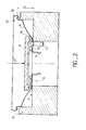
- FIG. 1 there is shown in section a housing member 11 of the booster, in position for the implementation of the method which will be described below.
- This housing element comprises an assembly ferrule 12 for subsequent crimping to another similar housing element, a flat bottom 13 for fixing and a web 14 connecting the ferrule 12 to the flat bottom 13.
- the profile final of the veil 14 is substantially paraboli than.
- an annular reinforcement 15 is applied to the internal face 16 of the base 13 to avoid deformation of the latter in the vicinity of fixing screws 17 (which can go as far as the removal of the screws) under the effect of the forces of reaction generated during braking, as explained above.
- the ferrule 12 is supported on a peripheral support 18 and the reinforcement 15 in place on the internal face 16 is applied a force of predetermined value, directed perpendicular to said internal face 16 and towards the outside of the housing element 11.
- a force of predetermined value directed perpendicular to said internal face 16 and towards the outside of the housing element 11.
- the application of the above-mentioned force has the effect of ensuring good cooperation between the parts in contact with the reinforcement 15 and the bottom 13. It must lead to permanent deformation of the housing element, in the axial direction, of a few tenths of a millimeter, but this deformation occurring at this stage in the development of the housing will subsequently guarantee perfectly elastic deflection of the housing during braking, which corresponds to the standards currently in force.
- the ferrule 12 of the housing element is supported on the peripheral support 18 by means of a folded edge 20 thereof which can be used for the subsequent assembly of two complementary housing elements.
- the implementation of the method is therefore particularly simple since it takes advantage of a feature of the already existing structure of the housing to position it during the implementation of the method described above.
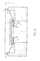
- the peripheral support 18 is however completed by a stop 21 with predetermined positioning (that is to say that the abutment surface 21 is at a predetermined distance "d" from the support zone defined by the support 18) on which the base 13 is likely to come to apply under the action of a force F 'exerted on the reinforcement 15 under the same conditions as above, that is to say by means of the pusher 19.
- the value of the force F ′ is less critical than in the method described in FIG. 1, it must however be sufficient to bring the bottom 13 into effective contact with the stop 21.
- This variant is advantageous insofar as the housing element 11 can be roughly preformed with the press, below its desired final shape, before the implementation of the described process, which allows to give said veil its shape and its final dimensions by the operation of bringing the base 13 into contact with the stop 21. It has been found that under such conditions, the final axial size of the housing element 11, after the force has disappeared F '(distance "x figure 3) was significantly better controlled at production.
- the invention is not limited to the two variant methods which have just been described.
- the invention covers all the technical equivalents of the means used if these are within the scope of the claims. that follow.
Landscapes
- Engineering & Computer Science (AREA)
- Mechanical Engineering (AREA)
- Transportation (AREA)
- Braking Systems And Boosters (AREA)
- Hydraulic Turbines (AREA)
- Motor Or Generator Frames (AREA)
- Making Paper Articles (AREA)
- Prostheses (AREA)
- Manufacture Of Motors, Generators (AREA)
- Braking Arrangements (AREA)
Claims (6)
Applications Claiming Priority (2)
| Application Number | Priority Date | Filing Date | Title |
|---|---|---|---|
| FR8103271A FR2499924A1 (fr) | 1981-02-19 | 1981-02-19 | Procede de conformage d'un element de servomoteur avec son renfort |
| FR8103271 | 1981-02-19 |
Publications (2)
| Publication Number | Publication Date |
|---|---|
| EP0060161A1 EP0060161A1 (de) | 1982-09-15 |
| EP0060161B1 true EP0060161B1 (de) | 1985-04-24 |
Family
ID=9255386
Family Applications (1)
| Application Number | Title | Priority Date | Filing Date |
|---|---|---|---|
| EP82400261A Expired EP0060161B1 (de) | 1981-02-19 | 1982-02-15 | Verfahren zum Formen eines Gehäuses für einen Servomotor mit einer Verstärkung |
Country Status (18)
| Country | Link |
|---|---|
| US (1) | US4445263A (de) |
| EP (1) | EP0060161B1 (de) |
| JP (1) | JPS57164850A (de) |
| KR (1) | KR880001731B1 (de) |
| AR (1) | AR226142A1 (de) |
| AU (1) | AU542829B2 (de) |
| BR (1) | BR8200853A (de) |
| CA (1) | CA1180172A (de) |
| DE (1) | DE3263216D1 (de) |
| ES (1) | ES8301788A1 (de) |
| FR (1) | FR2499924A1 (de) |
| MX (1) | MX157167A (de) |
| PL (1) | PL129408B1 (de) |
| PT (1) | PT74420B (de) |
| RO (1) | RO82947B (de) |
| SU (1) | SU1326188A3 (de) |
| TR (1) | TR22302A (de) |
| YU (1) | YU45858B (de) |
Families Citing this family (2)
| Publication number | Priority date | Publication date | Assignee | Title |
|---|---|---|---|---|
| US4574455A (en) * | 1984-09-04 | 1986-03-11 | Allied Corporation | Method of manufacturing a shell with an integral reinforcing plate |
| AU571785B2 (en) * | 1985-09-30 | 1988-04-21 | Jidosha Kiki Co. Ltd. | Brake booster |
Family Cites Families (8)
| Publication number | Priority date | Publication date | Assignee | Title |
|---|---|---|---|---|
| US2244927A (en) * | 1938-03-16 | 1941-06-10 | Thomas J Vanstone | Wheel press |
| US2696240A (en) * | 1949-10-28 | 1954-12-07 | Crowder John Hardin | Dent remover |
| FR2139613B1 (de) * | 1971-05-03 | 1974-04-05 | Dunlop Sa | |
| DE2129547B2 (de) * | 1971-06-10 | 1980-05-29 | Mannesmann Kronprinz Ag, 5650 Solingen | Verfahren zum Herstellen einer ebenen Anlageflaeche |
| US3756063A (en) * | 1972-04-27 | 1973-09-04 | Grotnes Machine Works Inc | Shrink forming apparatus with axial run-out tooling |
| DE2224027A1 (de) * | 1972-05-17 | 1973-11-22 | Ford Werke Ag | Verfahren zur rund- und planlaufkorrektur von stahlblechscheibenraedern, insbesondere fuer kraftfahrzeuge |
| FR2459166A1 (fr) * | 1979-06-15 | 1981-01-09 | Dba | Servomoteur d'assistance au freinage |
| JPS5766062A (en) * | 1980-10-01 | 1982-04-22 | Aisin Seiki Co Ltd | Attaching method for reinforcing plate of brake booster |
-
1981
- 1981-02-19 FR FR8103271A patent/FR2499924A1/fr active Granted
-
1982
- 1982-01-27 AU AU79876/82A patent/AU542829B2/en not_active Ceased
- 1982-02-01 US US06/344,277 patent/US4445263A/en not_active Expired - Lifetime
- 1982-02-01 KR KR8200404A patent/KR880001731B1/ko active
- 1982-02-04 CA CA000395573A patent/CA1180172A/en not_active Expired
- 1982-02-08 YU YU26382A patent/YU45858B/sh unknown
- 1982-02-10 RO RO106591A patent/RO82947B/ro unknown
- 1982-02-12 PT PT74420A patent/PT74420B/pt not_active IP Right Cessation
- 1982-02-15 EP EP82400261A patent/EP0060161B1/de not_active Expired
- 1982-02-15 DE DE8282400261T patent/DE3263216D1/de not_active Expired
- 1982-02-15 MX MX191391A patent/MX157167A/es unknown
- 1982-02-17 PL PL1982235120A patent/PL129408B1/pl unknown
- 1982-02-17 SU SU823390752A patent/SU1326188A3/ru active
- 1982-02-17 BR BR8200853A patent/BR8200853A/pt not_active IP Right Cessation
- 1982-02-18 AR AR288476A patent/AR226142A1/es active
- 1982-02-18 TR TR1158A patent/TR22302A/xx unknown
- 1982-02-18 ES ES509718A patent/ES8301788A1/es not_active Expired
- 1982-02-19 JP JP57024664A patent/JPS57164850A/ja active Granted
Also Published As
| Publication number | Publication date |
|---|---|
| BR8200853A (pt) | 1982-12-28 |
| PL129408B1 (en) | 1984-05-31 |
| JPH032702B2 (de) | 1991-01-16 |
| PT74420B (en) | 1983-11-15 |
| ES509718A0 (es) | 1983-01-16 |
| FR2499924B1 (de) | 1985-03-08 |
| SU1326188A3 (ru) | 1987-07-23 |
| ES8301788A1 (es) | 1983-01-16 |
| PL235120A1 (de) | 1982-10-25 |
| PT74420A (en) | 1982-03-01 |
| MX157167A (es) | 1988-10-31 |
| CA1180172A (en) | 1985-01-02 |
| KR880001731B1 (ko) | 1988-09-10 |
| TR22302A (tr) | 1987-01-15 |
| AU7987682A (en) | 1982-08-26 |
| YU26382A (en) | 1990-04-30 |
| KR830008869A (ko) | 1983-12-16 |
| AU542829B2 (en) | 1985-03-14 |
| DE3263216D1 (en) | 1985-05-30 |
| RO82947A (ro) | 1984-01-14 |
| RO82947B (ro) | 1984-01-30 |
| FR2499924A1 (fr) | 1982-08-20 |
| YU45858B (sh) | 1992-09-07 |
| US4445263A (en) | 1984-05-01 |
| JPS57164850A (en) | 1982-10-09 |
| AR226142A1 (es) | 1982-05-31 |
| EP0060161A1 (de) | 1982-09-15 |
Similar Documents
| Publication | Publication Date | Title |
|---|---|---|
| EP0039271B1 (de) | Befestigungsverstärkung für Hilfskraft-Bremsservomotor | |
| EP0153238B1 (de) | Bremskraftverstärker | |
| FR2482544A1 (fr) | Procede d'assemblage d'un maitre-cylindre a un amplificateur de force de freinage, notamment pour vehicules automobiles, et maitre-cylindre avec amplificateur de force de freinage assemble selon ce procede | |
| EP0060161B1 (de) | Verfahren zum Formen eines Gehäuses für einen Servomotor mit einer Verstärkung | |
| FR2476574A1 (fr) | Servomoteur d'assistance au freinage a structure allegee | |
| EP0300857B1 (de) | Zusammenbauverfahren für einen Servomotor und nach diesem Verfahren Zusammengebauter Servomotor | |
| FR2777851A1 (fr) | Servomoteur pneumatique a auto-assistance controlee en effort | |
| FR2540810A1 (fr) | Procede de montage d'un ensemble d'un servomoteur d'assistance au freinage et d'un maitre-cylindre sur une paroi fixe d'un vehicule, et servomoteur pour la mise en oeuvre de ce procede | |
| EP0021969A1 (de) | Bremshilfskraft-Servomotor | |
| FR2729355A1 (fr) | Ensemble d'un servomoteur pneumatique d'assistance au freinage et d'un maitre-cylindre | |
| EP0153888A1 (de) | Bremsverstärker | |
| FR2666552A1 (fr) | Procede de reglage de la valeur du saut d'un servomoteur pneumatique d'assistance au freinage et servomoteur pour la mise en óoeuvre de ce procede. | |
| EP1870306B1 (de) | Bremskraftverstärker mit Zugstangen, die verstärkte Dichtungsringe umfassen | |
| EP1623899B1 (de) | Pedalaufbau für ein Kraftfahrzeug | |
| EP0059139A1 (de) | Servomotor für Bremskraftverstärkung mit reduziertem Betätigungstotgang | |
| EP0516492B1 (de) | Sous ensemble de freinage pour véhicule | |
| EP1057704B1 (de) | Verbesserter Bremsverstärker | |
| EP0220987A1 (de) | Unterdruckbremskraftverstärker und Verfahren zu seiner Regelung | |
| FR2478563A1 (fr) | Amplificateur de force de freinage pour vehicules automobiles | |
| EP0371830B1 (de) | Bremsvorrichtung für Kraftfahrzeug | |
| EP0638034B1 (de) | Aus der trennwand zum motorraum und einem bremskraftverstärker gebildetes aufbauteil für kraftfahrzeuge | |
| EP0469937B1 (de) | Einstellverfahren für den Schwellenwert eines pneumatischen Bremskraftverstärkers und Servomotors zur Durchführung dieses Verfahrens | |
| FR2536715A1 (fr) | Ensemble de freinage a servo-assistance en parallele | |
| EP0746487A1 (de) | Pneumatischer bremskraftverstärker mit symmetrischem gehäuse | |
| EP1362756A1 (de) | Unterdruckbremskraftverstärker mit reduzierter Geräuscherzeugung |
Legal Events
| Date | Code | Title | Description |
|---|---|---|---|
| PUAI | Public reference made under article 153(3) epc to a published international application that has entered the european phase |
Free format text: ORIGINAL CODE: 0009012 |
|
| 17P | Request for examination filed |
Effective date: 19820310 |
|
| AK | Designated contracting states |
Designated state(s): BE DE GB IT NL SE |
|
| ITF | It: translation for a ep patent filed |
Owner name: ING. ZINI MARANESI & C. S.R.L. |
|
| GRAA | (expected) grant |
Free format text: ORIGINAL CODE: 0009210 |
|
| AK | Designated contracting states |
Designated state(s): BE DE GB IT NL SE |
|
| REF | Corresponds to: |
Ref document number: 3263216 Country of ref document: DE Date of ref document: 19850530 |
|
| PLBE | No opposition filed within time limit |
Free format text: ORIGINAL CODE: 0009261 |
|
| STAA | Information on the status of an ep patent application or granted ep patent |
Free format text: STATUS: NO OPPOSITION FILED WITHIN TIME LIMIT |
|
| PG25 | Lapsed in a contracting state [announced via postgrant information from national office to epo] |
Ref country code: BE Effective date: 19860228 |
|
| 26N | No opposition filed | ||
| BERE | Be: lapsed |
Owner name: S.A. D.B.A. Effective date: 19860228 |
|
| PG25 | Lapsed in a contracting state [announced via postgrant information from national office to epo] |
Ref country code: NL Effective date: 19860901 |
|
| NLV4 | Nl: lapsed or anulled due to non-payment of the annual fee | ||
| ITTA | It: last paid annual fee | ||
| EAL | Se: european patent in force in sweden |
Ref document number: 82400261.2 |
|
| PGFP | Annual fee paid to national office [announced via postgrant information from national office to epo] |
Ref country code: GB Payment date: 20010207 Year of fee payment: 20 |
|
| PGFP | Annual fee paid to national office [announced via postgrant information from national office to epo] |
Ref country code: SE Payment date: 20010221 Year of fee payment: 20 |
|
| PGFP | Annual fee paid to national office [announced via postgrant information from national office to epo] |
Ref country code: DE Payment date: 20010420 Year of fee payment: 20 |
|
| REG | Reference to a national code |
Ref country code: GB Ref legal event code: IF02 |
|
| PG25 | Lapsed in a contracting state [announced via postgrant information from national office to epo] |
Ref country code: GB Free format text: LAPSE BECAUSE OF EXPIRATION OF PROTECTION Effective date: 20020214 |
|
| REG | Reference to a national code |
Ref country code: GB Ref legal event code: PE20 Effective date: 20020214 |
|
| EUG | Se: european patent has lapsed |
Ref document number: 82400261.2 |