EP0059901B2 - Dispositif de commande à microprocesseur pour échelle orientable déployable ou bras élévateur analogue - Google Patents
Dispositif de commande à microprocesseur pour échelle orientable déployable ou bras élévateur analogue Download PDFInfo
- Publication number
- EP0059901B2 EP0059901B2 EP82101486A EP82101486A EP0059901B2 EP 0059901 B2 EP0059901 B2 EP 0059901B2 EP 82101486 A EP82101486 A EP 82101486A EP 82101486 A EP82101486 A EP 82101486A EP 0059901 B2 EP0059901 B2 EP 0059901B2
- Authority
- EP
- European Patent Office
- Prior art keywords
- microprocessor
- control
- movements
- ladder
- reach
- Prior art date
- Legal status (The legal status is an assumption and is not a legal conclusion. Google has not performed a legal analysis and makes no representation as to the accuracy of the status listed.)
- Expired - Lifetime
Links
- 230000033001 locomotion Effects 0.000 claims abstract description 127
- 230000015654 memory Effects 0.000 claims abstract description 39
- 125000004122 cyclic group Chemical group 0.000 claims abstract description 11
- 238000013459 approach Methods 0.000 claims abstract description 7
- 239000012190 activator Substances 0.000 claims abstract 4
- 230000004913 activation Effects 0.000 claims abstract 3
- 238000012937 correction Methods 0.000 claims description 15
- 238000005259 measurement Methods 0.000 claims description 15
- 230000001133 acceleration Effects 0.000 claims description 3
- 230000004044 response Effects 0.000 claims description 3
- 230000003213 activating effect Effects 0.000 claims description 2
- 230000002747 voluntary effect Effects 0.000 claims description 2
- 230000006870 function Effects 0.000 abstract description 12
- 238000010586 diagram Methods 0.000 description 22
- 235000021183 entrée Nutrition 0.000 description 10
- 238000011161 development Methods 0.000 description 8
- 238000012360 testing method Methods 0.000 description 8
- 239000000872 buffer Substances 0.000 description 7
- 230000000750 progressive effect Effects 0.000 description 7
- 238000012549 training Methods 0.000 description 6
- 230000008859 change Effects 0.000 description 5
- 230000035939 shock Effects 0.000 description 5
- 230000006978 adaptation Effects 0.000 description 4
- 238000012546 transfer Methods 0.000 description 4
- 238000012545 processing Methods 0.000 description 3
- 239000003381 stabilizer Substances 0.000 description 3
- 238000012795 verification Methods 0.000 description 3
- 230000003936 working memory Effects 0.000 description 3
- 230000002950 deficient Effects 0.000 description 2
- 230000007257 malfunction Effects 0.000 description 2
- 238000000034 method Methods 0.000 description 2
- 230000008569 process Effects 0.000 description 2
- 230000000284 resting effect Effects 0.000 description 2
- 230000011664 signaling Effects 0.000 description 2
- 241001415961 Gaviidae Species 0.000 description 1
- 241001080024 Telles Species 0.000 description 1
- 230000009471 action Effects 0.000 description 1
- 230000003321 amplification Effects 0.000 description 1
- 238000005452 bending Methods 0.000 description 1
- 230000008901 benefit Effects 0.000 description 1
- 230000008033 biological extinction Effects 0.000 description 1
- 230000005540 biological transmission Effects 0.000 description 1
- 230000000295 complement effect Effects 0.000 description 1
- 230000003247 decreasing effect Effects 0.000 description 1
- 238000006073 displacement reaction Methods 0.000 description 1
- 230000000694 effects Effects 0.000 description 1
- 238000009434 installation Methods 0.000 description 1
- 238000004519 manufacturing process Methods 0.000 description 1
- 230000005055 memory storage Effects 0.000 description 1
- 238000012986 modification Methods 0.000 description 1
- 230000004048 modification Effects 0.000 description 1
- 238000012544 monitoring process Methods 0.000 description 1
- 230000003472 neutralizing effect Effects 0.000 description 1
- 238000003199 nucleic acid amplification method Methods 0.000 description 1
- 230000003287 optical effect Effects 0.000 description 1
- 230000009467 reduction Effects 0.000 description 1
- 230000002441 reversible effect Effects 0.000 description 1
- 238000011076 safety test Methods 0.000 description 1
- 230000006641 stabilisation Effects 0.000 description 1
- 238000011105 stabilization Methods 0.000 description 1
- 230000001629 suppression Effects 0.000 description 1
- 239000000725 suspension Substances 0.000 description 1
Images


Classifications
-
- E—FIXED CONSTRUCTIONS
- E06—DOORS, WINDOWS, SHUTTERS, OR ROLLER BLINDS IN GENERAL; LADDERS
- E06C—LADDERS
- E06C5/00—Ladders characterised by being mounted on undercarriages or vehicles Securing ladders on vehicles
- E06C5/32—Accessories, e.g. brakes on ladders
- E06C5/36—Safety devices against slipping or falling of ladders; Safety devices against overloading ladders
-
- B—PERFORMING OPERATIONS; TRANSPORTING
- B66—HOISTING; LIFTING; HAULING
- B66C—CRANES; LOAD-ENGAGING ELEMENTS OR DEVICES FOR CRANES, CAPSTANS, WINCHES, OR TACKLES
- B66C23/00—Cranes comprising essentially a beam, boom, or triangular structure acting as a cantilever and mounted for translatory of swinging movements in vertical or horizontal planes or a combination of such movements, e.g. jib-cranes, derricks, tower cranes
- B66C23/88—Safety gear
- B66C23/90—Devices for indicating or limiting lifting moment
- B66C23/905—Devices for indicating or limiting lifting moment electrical
Definitions
- the present invention relates to a control device including the control and the safety of the movements of a ladder, such as for example a rescue and fire fighting ladder, or of a similar lifting arm mounted on a vehicle.
- Analog electronic control devices are known based on the following principle: an index symbolizes on a diagram the position of the end of the elevator and allows, thanks to a suitable coordinate axis system, the reading of the functional parameters.
- This index comprises a conductive part of the electric current which, during the movement of the index, switches electrically with the different zones of the diagram, themselves conductive and generally produced in the form of printed circuits. Switching with these zones produces the lighting or extinction of warning lights and possibly the automatic stop of movements when these become dangerous, in particular for the stability of the carrier vehicle.
- These devices are generally associated with an analog electromechanical or electronic logic system, which generates from information received from different sensors and the moving index, orders causing the change of state of indicators, the triggering of alarm (s) sound (s) or devices acting on the execution of movements.
- English patent application 2 050 294 relates generally to a steerable crane control involving a microprocessor, sensors of certain operating parameters, and comparisons with a table of limit data stored in memory, in order to trigger before exceeding these, an alarm and / or safety stop command for the crane movement.
- This must be regarded as a state of the art to which also relates the German patent application 2,836,337 as well as the European patent application 0 008 210.
- the English patent application 2 050 294 relates essentially (rev. 1) to a particular use of operating parameter to determine by calculation the actual working state of the boom (length and bending).
- the safety stop phase is provided for by a simple movement cut-off by relay (see description and claim 4).
- European patent application 0 008 210 relates essentially to an arrangement of optical encoders for processing the picked-up operating parameters chosen with a view to their processing and comparison with limit data.
- German patent application 2 836 337 relates to the joint use of two chains of different security parameters (double security) tested separately by a microcomputer intended to give only an alarm in the event of a fault indicated by one of the monitoring chains , and to continue the operation of the crane as long as the other chain does not in turn give contrary indication.
- German patent application no. 20 33 469 relates to the control of a scale on the basis of a measurement of the real torque and of a comparison of this real torque with a predetermined maximum torque.
- control device of the invention for a deployable orientable ladder, or similar lifting arm, provided with an articulated platform suitable for transporting one or more people comprises at least one raising or lowering control, a deployment and folding control and a pivoting control with members for manual selection of the desired movements, straightening and lowering, deployment and folding, and pivoting actuators, said selection members being adapted to supply representative electrical signals direction of control and the desired speed of execution of the desired movements.
- the device comprises a microprocessor reader of the control signals receiving said electrical signals.
- Said microprocessor comprises in memory: the maximum ranges not to be exceeded as a function of various selectable and predetermined parameters for bringing the scale into service, including choices of predetermined loads and predetermined scale orientations; a sequence of cyclic calculation of the actual range from information given by sensors for measuring the angle of training and the length deployed; a cyclic comparison sequence of the real range calculated with the maximum range corresponding to the predefined implementation conditions and whether or not authorizing the requested movement.
- Said microprocessor further includes in memory a law for decelerating the lowering and deployment movements at least, in predetermined terminal zones of evolution of these movements corresponding to a certain approach to the maximum predetermined range of use corresponding to the case of 'the use of the scale, taking into account the choice of load made by the user, said end zones being limited by said predetermined maximum operating range and being constantly recalculated by the microprocessor during movement.
- the microprocessor also includes in memory a cyclic comparison sequence, in this approach, of the displayed control speed with the speed derived from said law for each movement considered, intended to impose said law when the displayed control speed is excessive, by providing at the outputs of the microprocessor controlling these movements of the signals representative of the displayed control speed or automatically modified according to said law to reach the maximum predetermined range at zero speed; said outputs being connected to proportional electrical control members for activating the actuators of the movements considered.
- microprocessor control also makes it possible to limit the acceleration on switching on and off in response to orders for voluntary commands to switch on or off, by means of predetermined laws stored in memory.
- Such a command also lends itself to the digital display of the operating parameters with as high a precision as desired, whether in particular the current parameters or operating limits.
- Reaching the operating limit marked by the abovementioned automatic stopping process can also be advantageously accompanied by assistance with subsequent piloting by sending a spoken message indicating to the pilot the solution or solutions remaining at his disposal.
- Such a microprocessor control also has the advantage of being easily adaptable to all options of equipment of the equipment and of changes of the limits for which it suffices to modify the data taken into memory.
- the microprocessor also allows the command and automatic control of the horizontal alignment of the platform floor according to the angle of the ladder.
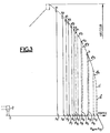
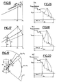
- a scale movement control and safety system aims to provide the user with the value of the operating parameters such as the angle of dressing ⁇ , the developed length L, the maximum possible load at the end of the ladder, the height reached H, the range P ... to alert the user and possibly stop the movements when they become dangerous, in particular in the event of an impact with an obstacle or in the event of being reached vehicle stability limits.
- This figure 3 symbolizes the usage diagrams corresponding to three possible positions of the support cylinders, but a continuous variation of the diagram can be envisaged.
- the different limits are stored in the control system.
- the control system compares the position of the ladder to each of the limits and lights up an indicator which corresponds to the possibility of maximum load. Automatic deployment, lowering and possibly pivoting movements are stopped when the ladder fitted with its rescue platform reaches the limit corresponding to the load case a1, a2, and a3, or when the ladder without rescue platform reaches the limit corresponding to a4, or the limits going from a'1 to a'4 or from a''1 to a''4 depending on the position of the beams 3.
- an audible device is activated to attract the attention of the user.
- a sensor When the rescue platform is used, a sensor signals its presence.
- Switches allow you to select the limits: two men plus platform, one man plus platform. Before reaching the usage limit corresponding to the chosen load case, a pre-signal intervenes as well as a slowing down of the maneuvers as will be seen below.
- the scale position information delivered by the various sensors is read periodically by the microprocessor and stored in memory.
- the microprocessor processes this data and compares the state of the scale with the limits of use stored in permanent memory.
- the microprocessor causes the automatic stop of this movement when the limit is reached, but after having achieved a progressive deceleration of the movement until the total stop and this whatever the command order given by the operator as we will see later.
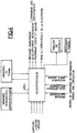
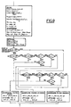
- the program plans to initialize the memory boxes in RAM.
- the MPU via the data BUS, by exciting the corresponding addresses, allows the transfer of REPROM to RAM of the initialization parameters.
- All digital inputs E1 to E34 are present as 1 or 0 at the terminals of the input BUFFERS.
- the MPU thanks to the addresses of the input PIA 1 and BUFFER 1, reads all of the inputs E1 to E16 which must be transferred to RAM by the BUS of the data and the memory addresses.
- All analog inputs E41 to E51 are present as a voltage across the terminals of analog input multiplexers.
- the MPU thanks to the addresses of the PIA 1, the multiplexer 1 and the A / D converter, reads the input E41, converted into digital and transfers by the BUS data and the address of the memory, the corresponding binary word in the RAM.
- the MPU When all the external data is in RAM memory, the MPU performs the calculations necessary for the smooth running of the program by going to draw from RAM by the data BUS and addresses the previously stored data.
- the display of the training angle, developed length, span and height parameters is done via the data buses and addresses of the PIA 2, the digital display decoder, and a 7-segment decoder for each digital output. , i.e. for S25 to S32 in a row.
- the MPU on each cycle, reads all the logic and analog inputs that it stores in RAM at the same addresses as before, the parameters already stored being automatically erased.
- the MPU performs all the calculations with this new information and the elements displayed are possibly updated.
- certain data are only displayed every 2 seconds for example.
- the MPU completes the program in a few milliseconds. This time is variable depending on the number of movements performed. In any event, each of the scale control parameters is read approximately 200 times per second.
- Self-checking of the inputs is included in the programs; for example, in measurements, if two successive readings of an analog input give a large deviation, the new value is not validated and other measurements are made. If this fault persists, the MPU, by displaying the number assigned to the faulty sensor, signals this incident and possibly stops the normal operation of the scale.
- the MPU checks whether the value of the analog input E47 (Measurement of the developed length) believes, if not, as previously, the reading of the input E47 is carried out several times, and if the anomaly persists, there is display of the number assigned to the sensor E47 and the operation of the ladder.
- the system thus performs a self-check and avoids giving erroneous orders in the event that it receives false information.
- the microprocessor also controls the display and signaling panel which informs the user about the state of the scale and its possibilities.
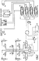
- Figure 7 shows the block diagram of the hydraulic movement control circuit.
- a variable flow pump 52 supplies the entire installation from a reservoir 53.
- the telescopic beams which support the chocks are controlled by distributors 54 and 55 which respectively supply the jacks 56 of the left beams and the cylinders 57 of the right beams.
- a distributor 58 ensures the actuation of cylinders 59 for neutralizing the elastic suspension of the vehicle and of the timing cylinders 2.
- a pressure switch 60 registers the resulting pressure increase and it establishes the energizing the electronic system of the ladder via input E1. Therefore, the control of the movements of the scale itself is possible by action on the proportional solenoid valves 61, 62, 63 and 64.
- the solenoid valve 61 controls the deployment-folding movement through the hydraulic motor 65 which actuates a winch.
- the solenoid valve 62 controls the dressing-lowering movement by means of the jacks 66.
- the solenoid valve 63 feeds the tilt correction cylinders 67 which cause the part 5 of the turret to rotate.
- the solenoid valve 64 controls the pivoting movement to the right or to the left by means of the motor 68.
- Each of the solenoid valves 61, 62, 63, 64 is of the proportional type, that is to say it delivers a flow proportional to the control voltage of the coils.
- the microprocessor cuts the electrical supply to the distributor 51, output S19 of the microprocessor (control oil pressure of the pump at zero value by exit status 0).
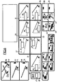
- FIG. 8 shows the general flowchart of the operations carried out by the electronic microprocessor system.
- the program then includes the scale overload test (Input E51).
- the program then includes the successive control of the different movements:
- the principle of movement control is the same for all movements except the folding back, for which the automatic concordance of the steps can be superimposed.
- Figures 9, 10 and 11 show the detailed flowchart for the calculation of heights and spans, the memorization of the position of the support beams of the stabilizer jacks, the display of the authorized load limits and the storage of the limit range corresponding to the operating case.
- the microprocessor after having read all the input parameters, calculates the range P, the height H, the maximum values of developable length L maxi before automatic stop at constant angle of dressing and corresponding maximum height H, the maximum value of the dressing angle ⁇ 2 corresponding to the maximum range for which there must be an automatic stop at constant developed length L; the angle of dressing ⁇ r, the range Pr and the developed length Lr at the start of slowing down of the movements.
- ⁇ corresponds to an angular range of deceleration of the lowering before automatic stop
- ⁇ P and ⁇ L to two ranges of deceleration before automatic stop in range or developed length.
- the different values taken into account are stored in memories indicated in the “Calculation” box of FIG. 9, by the letter M followed by an identification index.
- the microprocessor uses the memory M20 in which the maximum range corresponding to the use of the scale is stored (fig. 3 and 11).
- the microprocessor then checks in what position the timing cylinders 2 are and what is the orientation ⁇ of the scale relative to the longitudinal axis of the vehicle. If the orientation ⁇ of the scale does not differ by more than ⁇ 25 ° from the longitudinal axis of the vehicle, the useful range is the maximum range for the load considered and it is independent of the position of the stabilizers. For different orientations of the scale, the microprocessor memorizes the position of the beams located on the side where the scale is oriented (memories M2, M3, M4, fig. 9).
- the microprocessor then displays the load case (fig. 10). It examines whether the ladder is used with or without its platform (entry E9) what is the choice of load made by the user (1, 2 or 3 men on the platform, resting ladder, entries E10, E11, E12) and it compares, in the case of the scale used without a platform, the actual range of the scale stored in the memory M21, with the limit ranges authorized as a function of the position of the stabilizers; it deduces the maximum possible load therefrom and proceeds to switch on the corresponding warning light and extinguish the other warning lights by outputs S3 to S9 (warning lights 33 to 39).
- the microprocessor then checks if there is a concordance of steps and displays the corresponding display (LED 41).
- the following sequence relates to the emission of an audible signal when there is a change of load case; thus an audible signal of duration 1 second is emitted when the range becomes equal to P4, P5, P6, P7, P8 or P9.
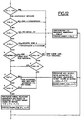
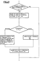
- FIG. 12 The operating principle of motion control is described using FIG. 12, taking the example of the lowering of the scale (with analog signals in the form of voltage).
- the operator via a Dressage / Lowering control manipulator, requests the lowering of the scale and sends a voltage proportional to the requested speed to the electronic system.
- the command and control system checks whether the requested movement can be executed according to the various safety parameters entered in the program and generates, if there is compatibility, the control signal (output S33) which will be taken into account by the solenoid valve (62) for controlling the movement in question.
- the MPU sets the output S33 to 0 (or maintains it if it was previously there).
- the MPU checks, in the order of the program, the logical values of the inputs E18, E25 and E29 (stored in RAM). If one of them is at 1, the output S33 is set (or maintained) at 0.
- test A and B the verification of the position of the ladder in relation to the pivoting and straightening / lowering chassis to avoid any interference with the vehicle cabin.
- test C is done.
- the analog output S33 generates a signal proportional to the input E41 with a decreasing maximum value in accordance with a deceleration curve with end of travel stop, REPROM memory storage and which will be seen later.
- the MPU checks logic input E27 (test D) and test E.
- the output S33 If D or E is positive, the output S33 generates, as above, a signal proportional to the input E41 with maximum value limited by said deceleration curve before end of travel.
- the MPU If D and E are negative, the MPU generates a signal proportional to the input E41 without correction except in the event of a sudden request or suppression of the motion control (input E41) or in this case the MPU generates the output signal at l acceleration and deceleration, according to other speed control curves stored in REPROM memory, this in order to have greater comfort in piloting the ladder and to avoid unpleasant mechanical stresses on the ladder.
- the MPU which manages the output S33 can, without waiting for a deviation from the horizontality of the platform, simultaneously control its alignment by generating a proportional signal to S33 on the output S36: proportional control for horizontal positioning of the platform 11, this proportional control being able to cooperate with an actuator not shown, such as an electric actuator interposed between the last rung 10 of the scale and the platform to vary the angle ⁇ .
- a control loop is incorporated into the program, which allows, by measuring the angle ⁇ of the platform with respect to the scale (E45) to put in the program a correction parameter making it possible to remove the deviations due to the electro-hydro-mechanical system for controlling the power of the ladder's movements.
- the training command is controlled and executed by the MPU according to the same principle as the lowering command above, with of course, parameters to control specific to this movement.
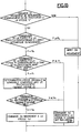
- FIG. 13 defines the principle flow diagram of the automatic slowing down of the pivoting, lowering or deployment movements before automatic stopping, corresponding to the maximum admissible range.
- the microprocessor receives the operator's movement orders. If the range P is greater than or equal to the maximum admissible range Pa, the microprocessor does not control the movement.
- the microprocessor compares the range P with the range Pr corresponding to the start of the zone where the movement must be slowed down in order to reach the automatic stopping point at zero speed.
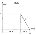
- Figure 14 illustrates the diagram of the speed of movement as a function of the space traveled.
- the speed of the movement is that requested by the operator and it can go up to the maximum speed Vm allowed by the control systems.
- zone B corresponding to a range P greater than Pr and less than Pa, the microprocessor imposes a maximum speed defined by the limit C which joins the point of start of deceleration where the speed can be maximum at the point of end of deceleration where the speed must be zero.
- zone B the microprocessor controls the movement at the speed requested by the operator as long as this is lower than the limit speed defined by curve C, then at the speed corresponding to this curve C when the speed requested by l operator becomes superior to the latter.
- a movement slowdown system is only effectively achievable thanks to the use of a microprocessor because the slowdown zones of each movement are a function of the large number of parameters on which the limit range Pa depends and they must be constantly recalculated in course of movement, as we have seen, the various movements of the scale being able to be simultaneous and influencing the limit range Pa.
- the microprocessor thus limits in all cases the harmful dynamic effects and in particular any swinging of the undesirable scale.
- the slowing down of the various movements can be controlled in the following manner by the microprocessor.
- the microprocessor calculates the maximum admissible speed for each movement corresponding to a progressive deceleration. For this, each movement is considered as if it were executed alone, this being possible only thanks to the very high calculation speed of the microprocessor.
- V Lm (N) V LMaxi [1- (1 / n1) x
- the microprocessor which has in memory the speed-command relation S34 of the development movement, determines the maximum command command S34 m which corresponds to the maximum admissible speed V Lm (N).
- V ⁇ m (R) V ⁇ Maxi [1- (1 / n2) x
- the microprocessor which has in memory the speed-command relationship S33 of the lowering movement determines the maximum command order S33 m which corresponds to the maximum admissible speed V ⁇ m (R).
- the range Pa corresponding to the automatic stop may change, for example when the scale deviates from the longitudinal axis of the vehicle and the beams of the jacks are retracted or half-extended.
- the microprocessor which has in memory the speed-command relation S35 of the pivoting movement, determines the maximum command command S35 m which corresponds to the maximum admissible speed V ⁇ m (T).
- FIG. 21 defines the principle flow diagram for the horizontal positioning of the working platform 11.
- the microprocessor simultaneously controls the angular movement of the platform and the raising or lowering of the ladder at the same speed.
- sensors of known types such as potentiometers or angular encoders measure the angle of dressing ⁇ and the angle ⁇ of the platform floor relative to the scale.
- the microprocessor calculates the speed necessary to follow the raising or lowering movement and to remove the position deviation after a defined time, for example 5 seconds.
- This device which performs the simultaneous angular movement of the platform 11 and of the ladder makes it possible to have the platform horizontally precise and smoothly, which improves the comfort of the passengers.
- the microprocessor When the operator requests a movement which becomes dangerous for the stability of the vehicle, the microprocessor thus causes, as explained, the automatic stopping of this movement when the limit is reached, after having achieved the progressive deceleration of this movement.
- the movement being stopped the light requesting training or folding back (S11 - light 45, fig. 6) lights up.
- the operator who may be in a context of panic, may not react immediately and wonder why the ladder is no longer ordered. It is then that the transmission of a spoken message takes on its full value and is here provided from the microprocessor according to the diagram in FIG. 22.
- the microprocessor at this time, sends by BUS, the information necessary for the dissemination of the message corresponding to the scenario that caused the automatic shutdown.
- the memory circuits 69 and speech synthesizer 70 manufacture the sentence to be broadcast which, after amplification at 71 is transmitted to a loudspeaker 72 placed near the ladder operator acting in the vehicle.
- a second listening station 73 can be placed at the ladder control station located in the platform 11 to inform an operator acting from the platform.
- microprocessor also allows greater ease of adaptation to particular constraints.
- the operating limits change and it suffices to modify the values stored in memory.
- modifications or options are requested in the security system, it suffices to add additional sensors if necessary and to modify the program. This means that many variants can be easily adapted while remaining within the scope of the invention.
Landscapes
- Engineering & Computer Science (AREA)
- Mechanical Engineering (AREA)
- Ladders (AREA)
- Programmable Controllers (AREA)
- Manipulator (AREA)
Priority Applications (1)
| Application Number | Priority Date | Filing Date | Title |
|---|---|---|---|
| AT82101486T ATE11950T1 (de) | 1981-03-05 | 1982-02-26 | Steuergeraet mit einem mikroprozessor fuer eine drehbare, ausfahrbare leiter oder einen gleichartigen hebearm. |
Applications Claiming Priority (2)
| Application Number | Priority Date | Filing Date | Title |
|---|---|---|---|
| FR8104449 | 1981-03-05 | ||
| FR8104449A FR2501390A1 (fr) | 1981-03-05 | 1981-03-05 | Dispositif de commande a microprocesseur pour echelle orientable deployable ou bras elevateur analogue |
Publications (3)
| Publication Number | Publication Date |
|---|---|
| EP0059901A1 EP0059901A1 (fr) | 1982-09-15 |
| EP0059901B1 EP0059901B1 (fr) | 1985-02-20 |
| EP0059901B2 true EP0059901B2 (fr) | 1996-09-04 |
Family
ID=9255906
Family Applications (1)
| Application Number | Title | Priority Date | Filing Date |
|---|---|---|---|
| EP82101486A Expired - Lifetime EP0059901B2 (fr) | 1981-03-05 | 1982-02-26 | Dispositif de commande à microprocesseur pour échelle orientable déployable ou bras élévateur analogue |
Country Status (6)
| Country | Link |
|---|---|
| EP (1) | EP0059901B2 (OSRAM) |
| AT (1) | ATE11950T1 (OSRAM) |
| DE (1) | DE3262363D1 (OSRAM) |
| ES (1) | ES8305510A1 (OSRAM) |
| FR (1) | FR2501390A1 (OSRAM) |
| MA (1) | MA19406A1 (OSRAM) |
Cited By (2)
| Publication number | Priority date | Publication date | Assignee | Title |
|---|---|---|---|---|
| WO2006000645A1 (en) * | 2004-06-29 | 2006-01-05 | Bronto Skylift Oy Ab | Ladder arrangement, person lifter and method of using a person lifter |
| US11447379B2 (en) | 2018-10-09 | 2022-09-20 | J.C. Bamford Excavators Limited | Machine, controller and control method |
Families Citing this family (16)
| Publication number | Priority date | Publication date | Assignee | Title |
|---|---|---|---|---|
| GB8406094D0 (en) * | 1984-03-08 | 1984-04-11 | Merryweather & Sons | Control system |
| EP0196888B1 (en) * | 1985-03-28 | 1990-10-03 | Kabushiki Kaisha Hikoma Seisakusho | Lifting apparatus |
| FR2583898B1 (fr) * | 1985-06-21 | 1988-05-20 | Camiva Sa | Procede de commande d'une echelle sur vehicule |
| ES2050748T3 (es) * | 1989-03-16 | 1994-06-01 | Ppm Sa | Procedimiento y dispositivo para el mando de las funciones de grua de una grua movil con pluma telescopica. |
| JP2564060B2 (ja) * | 1991-10-24 | 1996-12-18 | 株式会社神戸製鋼所 | 建設機械の安全装置 |
| DE4223695C2 (de) * | 1992-07-21 | 1994-12-08 | Weber Anlagenbau Gmbh & Co Kg | Steuerung für das Verschwenken eines in seiner effektiven Länge veränderlichen Auslegers |
| DE29519871U1 (de) * | 1995-12-14 | 1996-03-21 | Liebherr-Werk Ehingen Gmbh, 89584 Ehingen | Kranfahrzeug |
| DE29519928U1 (de) * | 1995-12-15 | 1996-04-04 | Liebherr-Werk Ehingen Gmbh, 89584 Ehingen | Kranfahrzeug mit einer Überlastsicherungseinrichtung |
| FR2750972B1 (fr) * | 1996-07-12 | 1998-10-02 | Fdi Sambron | Chariot de manutention pourvu d'un systeme de securite permettant d'eviter son basculement accidentel |
| GB2471134B (en) | 2009-06-19 | 2012-10-10 | Bamford Excavators Ltd | Speed sensitive longitudinal load moment control of a working machine |
| CN102536103B (zh) * | 2011-12-30 | 2013-12-04 | 长沙中联消防机械有限公司 | 一种臂架回收的控制方法、控制装置、控制系统及车辆 |
| CN103100150B (zh) * | 2013-02-22 | 2015-04-08 | 王永庆 | 一种高空救援装置及其组装方法 |
| EP3431436B1 (fr) | 2017-07-17 | 2020-04-15 | Manitou Bf | Procédé de commande d'une machine de manutention et machine de manutention correspondante |
| EP3431435B1 (fr) * | 2017-07-17 | 2020-04-22 | Manitou Bf | Commande d'une machine de manutention |
| IT201800004135A1 (it) | 2018-03-30 | 2019-09-30 | Manitou Italia Srl | Macchina operatrice semovente di tipo articolato. |
| CN113880015A (zh) * | 2021-09-02 | 2022-01-04 | 潍柴动力股份有限公司 | 高空作业平台控制方法、装置、电子设备和存储介质 |
Family Cites Families (4)
| Publication number | Priority date | Publication date | Assignee | Title |
|---|---|---|---|---|
| US4216868A (en) * | 1978-08-04 | 1980-08-12 | Eaton Corporation | Optical digital sensor for crane operating aid |
| DE2836337C2 (de) * | 1978-08-19 | 1987-01-22 | Iveco Magirus AG, 7900 Ulm | Einrichtung für das Schalten und Überwachen der Bewegungen einer motorisch angetriebenen Drehleiter oder dergleichen höhenveränderlicher Arbeitsgeräte |
| JPS55129085A (en) * | 1979-03-26 | 1980-10-06 | Janome Sewing Machine Co Ltd | Electronic sewing machine |
| GB2050294B (en) * | 1979-05-18 | 1983-04-07 | Coles Cranes Ltd | Safe load indicator |
-
1981
- 1981-03-05 FR FR8104449A patent/FR2501390A1/fr active Granted
-
1982
- 1982-02-26 AT AT82101486T patent/ATE11950T1/de not_active IP Right Cessation
- 1982-02-26 DE DE8282101486T patent/DE3262363D1/de not_active Expired
- 1982-02-26 EP EP82101486A patent/EP0059901B2/fr not_active Expired - Lifetime
- 1982-03-04 ES ES510139A patent/ES8305510A1/es not_active Expired
- 1982-03-05 MA MA19611A patent/MA19406A1/fr unknown
Cited By (2)
| Publication number | Priority date | Publication date | Assignee | Title |
|---|---|---|---|---|
| WO2006000645A1 (en) * | 2004-06-29 | 2006-01-05 | Bronto Skylift Oy Ab | Ladder arrangement, person lifter and method of using a person lifter |
| US11447379B2 (en) | 2018-10-09 | 2022-09-20 | J.C. Bamford Excavators Limited | Machine, controller and control method |
Also Published As
| Publication number | Publication date |
|---|---|
| FR2501390A1 (fr) | 1982-09-10 |
| ATE11950T1 (de) | 1985-03-15 |
| ES510139A0 (es) | 1983-04-01 |
| FR2501390B1 (OSRAM) | 1984-06-22 |
| MA19406A1 (fr) | 1982-10-01 |
| ES8305510A1 (es) | 1983-04-01 |
| EP0059901B1 (fr) | 1985-02-20 |
| EP0059901A1 (fr) | 1982-09-15 |
| DE3262363D1 (en) | 1985-03-28 |
Similar Documents
| Publication | Publication Date | Title |
|---|---|---|
| EP0059901B2 (fr) | Dispositif de commande à microprocesseur pour échelle orientable déployable ou bras élévateur analogue | |
| US4942529A (en) | Lift truck control systems | |
| EP0802469B1 (fr) | Dispositif d'anti-collision terrain pour aéronef avec prédiction de virage | |
| CA2472290C (fr) | Systeme d'aide a la commande de la deceleration d'un aeronef roulant sur le sol | |
| WO2007093698A1 (fr) | Procede et systeme pour predire la possibilite d’arret complet d’un aeronef sur une piste d’atterissage | |
| EP1907910A2 (fr) | Procede et dispositif de securisation d'un vol automatique a basse altitude d'un aeronef | |
| JP2020052070A (ja) | ヘッドアップディスプレイ装置 | |
| JP6966539B2 (ja) | 緊急車両のための操作方法 | |
| EP1600838B1 (fr) | Procédé et dispositif de sécurisation d'un vol à basse altitude d'un aéronef | |
| FR2628375A1 (fr) | Procede et installation pour la commande automatique d'un vehicule guide | |
| CA2640321A1 (fr) | Procede et dispositif de detection d'une dissymetrie laterale d'un aeronef | |
| EP3915929B1 (fr) | Système de gestion d'anticollision d'une grue mobile sur un chantier | |
| FR3053313A1 (fr) | Systeme de positionnement de charge automatique pour un helicoptere equipe d un treuil exterieur | |
| CA2502503C (fr) | Indicateur de pilotage pour un aeronef. | |
| FR3086075A1 (fr) | Systeme electronique de supervision d'un vehicule autonome, procede et programme d'ordinateur associes | |
| CH659983A5 (fr) | Dispositif d'avertissement pour le pilote d'un avion effectuant une manoeuvre de combat. | |
| EP3912950B1 (fr) | Système de gestion de modes de travail d'une grue mobile sur un chantier | |
| EP0252841A1 (fr) | Dispositif de commande de ralentissement automatique de la rotation de flèche et/ou de contreflèches d'engins de levage | |
| JP3649781B2 (ja) | タワークレーンの安全装置 | |
| EP0392938A1 (fr) | Dispositif de freinage de sécurité d'un funiculaire | |
| EP1249813B1 (fr) | Dispositif de commande d'un système de surveillance de l'environnement d'un aéronef | |
| KR20220030605A (ko) | 타워 크레인 안전 관제 시스템 | |
| FR2502772A1 (fr) | Procede et dispositif de mesure des trois coordonnees d'un aeronef en point fixe par rapport a un point au sol | |
| FR2494245A1 (fr) | Systeme d'alerte anti-collision entre grues a tour | |
| FR3103975A1 (fr) | Boitier pour la robotisation d’un engin de manutention |
Legal Events
| Date | Code | Title | Description |
|---|---|---|---|
| PUAI | Public reference made under article 153(3) epc to a published international application that has entered the european phase |
Free format text: ORIGINAL CODE: 0009012 |
|
| AK | Designated contracting states |
Designated state(s): AT BE CH DE GB IT NL SE |
|
| 17P | Request for examination filed |
Effective date: 19830315 |
|
| ITF | It: translation for a ep patent filed | ||
| GRAA | (expected) grant |
Free format text: ORIGINAL CODE: 0009210 |
|
| AK | Designated contracting states |
Designated state(s): AT BE CH DE GB IT LI NL SE |
|
| REF | Corresponds to: |
Ref document number: 11950 Country of ref document: AT Date of ref document: 19850315 Kind code of ref document: T |
|
| REF | Corresponds to: |
Ref document number: 3262363 Country of ref document: DE Date of ref document: 19850328 |
|
| PLBI | Opposition filed |
Free format text: ORIGINAL CODE: 0009260 |
|
| PLBI | Opposition filed |
Free format text: ORIGINAL CODE: 0009260 |
|
| 26 | Opposition filed |
Opponent name: IVECO MAGIRUS AG Effective date: 19851102 |
|
| 26 | Opposition filed |
Opponent name: DR.-ING. LUDWIG PIETZSCH GMBH & CO. Effective date: 19851118 |
|
| NLR1 | Nl: opposition has been filed with the epo |
Opponent name: IVECO MAGIRUS AG |
|
| NLR1 | Nl: opposition has been filed with the epo |
Opponent name: DR.-ING. LUDWIG PIETZSCH GMBH & CO. |
|
| PLAB | Opposition data, opponent's data or that of the opponent's representative modified |
Free format text: ORIGINAL CODE: 0009299OPPO |
|
| R26 | Opposition filed (corrected) |
Opponent name: IVECO MAGIRUS AG * 851118 DR.-ING. LUDWIG PIETZSCH Effective date: 19851102 |
|
| ITTA | It: last paid annual fee | ||
| PLAB | Opposition data, opponent's data or that of the opponent's representative modified |
Free format text: ORIGINAL CODE: 0009299OPPO |
|
| R26 | Opposition filed (corrected) |
Opponent name: IVECO MAGIRUS AG * 851118 DR.-ING. LUDWIG PIETZSCH Effective date: 19851102 |
|
| PLAB | Opposition data, opponent's data or that of the opponent's representative modified |
Free format text: ORIGINAL CODE: 0009299OPPO |
|
| R26 | Opposition filed (corrected) |
Opponent name: IVECO MAGIRUS AG * 851118 DR.-ING. LUDWIG PIETZSCH Effective date: 19851102 |
|
| EAL | Se: european patent in force in sweden |
Ref document number: 82101486.7 |
|
| PLAW | Interlocutory decision in opposition |
Free format text: ORIGINAL CODE: EPIDOS IDOP |
|
| PLAW | Interlocutory decision in opposition |
Free format text: ORIGINAL CODE: EPIDOS IDOP |
|
| PUAH | Patent maintained in amended form |
Free format text: ORIGINAL CODE: 0009272 |
|
| STAA | Information on the status of an ep patent application or granted ep patent |
Free format text: STATUS: PATENT MAINTAINED AS AMENDED |
|
| REG | Reference to a national code |
Ref country code: CH Ref legal event code: NV Representative=s name: AMMANN PATENTANWAELTE AG BERN |
|
| 27A | Patent maintained in amended form |
Effective date: 19960904 |
|
| AK | Designated contracting states |
Kind code of ref document: B2 Designated state(s): AT BE CH DE GB IT LI NL SE |
|
| REG | Reference to a national code |
Ref country code: CH Ref legal event code: AEN Free format text: MAINTIEN DU BREVET DONT L'ETENDUE A ETE MODIFIEE |
|
| NLR2 | Nl: decision of opposition | ||
| ITF | It: translation for a ep patent filed | ||
| PGFP | Annual fee paid to national office [announced via postgrant information from national office to epo] |
Ref country code: GB Payment date: 19970113 Year of fee payment: 16 |
|
| PGFP | Annual fee paid to national office [announced via postgrant information from national office to epo] |
Ref country code: BE Payment date: 19970116 Year of fee payment: 16 |
|
| PGFP | Annual fee paid to national office [announced via postgrant information from national office to epo] |
Ref country code: SE Payment date: 19970123 Year of fee payment: 16 |
|
| PGFP | Annual fee paid to national office [announced via postgrant information from national office to epo] |
Ref country code: DE Payment date: 19970124 Year of fee payment: 16 |
|
| PGFP | Annual fee paid to national office [announced via postgrant information from national office to epo] |
Ref country code: AT Payment date: 19970128 Year of fee payment: 16 |
|
| PGFP | Annual fee paid to national office [announced via postgrant information from national office to epo] |
Ref country code: NL Payment date: 19970130 Year of fee payment: 16 |
|
| PGFP | Annual fee paid to national office [announced via postgrant information from national office to epo] |
Ref country code: CH Payment date: 19970131 Year of fee payment: 16 |
|
| NLR3 | Nl: receipt of modified translations in the netherlands language after an opposition procedure | ||
| PG25 | Lapsed in a contracting state [announced via postgrant information from national office to epo] |
Ref country code: GB Free format text: LAPSE BECAUSE OF NON-PAYMENT OF DUE FEES Effective date: 19980226 Ref country code: AT Free format text: LAPSE BECAUSE OF NON-PAYMENT OF DUE FEES Effective date: 19980226 |
|
| PG25 | Lapsed in a contracting state [announced via postgrant information from national office to epo] |
Ref country code: SE Free format text: LAPSE BECAUSE OF NON-PAYMENT OF DUE FEES Effective date: 19980227 |
|
| PG25 | Lapsed in a contracting state [announced via postgrant information from national office to epo] |
Ref country code: LI Free format text: LAPSE BECAUSE OF NON-PAYMENT OF DUE FEES Effective date: 19980228 Ref country code: CH Free format text: LAPSE BECAUSE OF NON-PAYMENT OF DUE FEES Effective date: 19980228 Ref country code: BE Free format text: LAPSE BECAUSE OF NON-PAYMENT OF DUE FEES Effective date: 19980228 |
|
| BERE | Be: lapsed |
Owner name: CAMIVA Effective date: 19980228 |
|
| PG25 | Lapsed in a contracting state [announced via postgrant information from national office to epo] |
Ref country code: NL Free format text: LAPSE BECAUSE OF NON-PAYMENT OF DUE FEES Effective date: 19980901 |
|
| GBPC | Gb: european patent ceased through non-payment of renewal fee |
Effective date: 19980226 |
|
| REG | Reference to a national code |
Ref country code: CH Ref legal event code: PL |
|
| EUG | Se: european patent has lapsed |
Ref document number: 82101486.7 |
|
| NLV4 | Nl: lapsed or anulled due to non-payment of the annual fee |
Effective date: 19980901 |
|
| PG25 | Lapsed in a contracting state [announced via postgrant information from national office to epo] |
Ref country code: DE Free format text: LAPSE BECAUSE OF NON-PAYMENT OF DUE FEES Effective date: 19981103 |
|
| APAH | Appeal reference modified |
Free format text: ORIGINAL CODE: EPIDOSCREFNO |