EP0059652A1 - Wave energy harnessing device - Google Patents
Wave energy harnessing device Download PDFInfo
- Publication number
- EP0059652A1 EP0059652A1 EP82400171A EP82400171A EP0059652A1 EP 0059652 A1 EP0059652 A1 EP 0059652A1 EP 82400171 A EP82400171 A EP 82400171A EP 82400171 A EP82400171 A EP 82400171A EP 0059652 A1 EP0059652 A1 EP 0059652A1
- Authority
- EP
- European Patent Office
- Prior art keywords
- vessel
- liquid
- compartments
- swell
- pitch
- Prior art date
- Legal status (The legal status is an assumption and is not a legal conclusion. Google has not performed a legal analysis and makes no representation as to the accuracy of the status listed.)
- Withdrawn
Links
Images

Classifications
-
- F—MECHANICAL ENGINEERING; LIGHTING; HEATING; WEAPONS; BLASTING
- F03—MACHINES OR ENGINES FOR LIQUIDS; WIND, SPRING, OR WEIGHT MOTORS; PRODUCING MECHANICAL POWER OR A REACTIVE PROPULSIVE THRUST, NOT OTHERWISE PROVIDED FOR
- F03B—MACHINES OR ENGINES FOR LIQUIDS
- F03B13/00—Adaptations of machines or engines for special use; Combinations of machines or engines with driving or driven apparatus; Power stations or aggregates
- F03B13/12—Adaptations of machines or engines for special use; Combinations of machines or engines with driving or driven apparatus; Power stations or aggregates characterised by using wave or tide energy
- F03B13/14—Adaptations of machines or engines for special use; Combinations of machines or engines with driving or driven apparatus; Power stations or aggregates characterised by using wave or tide energy using wave energy
- F03B13/22—Adaptations of machines or engines for special use; Combinations of machines or engines with driving or driven apparatus; Power stations or aggregates characterised by using wave or tide energy using wave energy using the flow of water resulting from wave movements to drive a motor or turbine
-
- Y—GENERAL TAGGING OF NEW TECHNOLOGICAL DEVELOPMENTS; GENERAL TAGGING OF CROSS-SECTIONAL TECHNOLOGIES SPANNING OVER SEVERAL SECTIONS OF THE IPC; TECHNICAL SUBJECTS COVERED BY FORMER USPC CROSS-REFERENCE ART COLLECTIONS [XRACs] AND DIGESTS
- Y02—TECHNOLOGIES OR APPLICATIONS FOR MITIGATION OR ADAPTATION AGAINST CLIMATE CHANGE
- Y02E—REDUCTION OF GREENHOUSE GAS [GHG] EMISSIONS, RELATED TO ENERGY GENERATION, TRANSMISSION OR DISTRIBUTION
- Y02E10/00—Energy generation through renewable energy sources
- Y02E10/30—Energy from the sea, e.g. using wave energy or salinity gradient
Definitions
- the present invention relates to a device making it possible to use the energy of swells and waves to produce electricity or any other form of energy usable on land from an anchored vessel which has means of producing energy and its transmission to dry land.
- the present invention is intended to remedy these drawbacks.
- the device of the invention consists in capturing the energy of the swell and of the waves by means of liquid fluids, held in closed spaces, moved in a back and forth movement by pitching. These fluids, of very large masses, driven by high speeds, drive hydraulic wheels, turbines, or any other means of transformation or direct use of this energy.
- the normally embossed vessel is properly positioned in front of the swell and is held there either by lateral impellers with paddlewheels or by stern thrusters which laterally push the rear of the vessel to one side or the other.
- An advantageous characteristic of the invention resides in the fact that the amplitude of the pitch is controlled by means of bells arranged vertically at the front and at the rear of the vessel, bells in the upper part of which the pressure of the the air.
- the sealed compartments are interrupted towards the middle of the vessel by machine compartments.
- These compartments may include bulb groups, the blades of which change orientation each time the vessel's inclination changes.
- These compartments may also include, per turbine, at least two large valves upstream and downstream of each of the turbines to ensure a flow of liquid always moving in the same direction on the turbine regardless of the direction of flow of the liquid the along the ship.
- the drive fluid for the turbines is assigned a circuit passing through rear transfer compartments, transfer compartments from rear to front, front storage compartments and compartments rear storage, the turbine being arranged at the output of each storage compartment and large valves being provided at the end of each compart- ment ti transfer the input of each storage compartment to always maintain the same direction of rotation of liquid in the circuit.
- tanks are provided at the bottom of the hold, to recover the working liquid, in the event of an interruption in operation.
- this liquid could be sea water, in which case its recovery would be of no interest; however, as will be seen below, it would be beneficial to use dense liquids whose price is not negligible and which would have to be recovered.
- the device of the invention uses a vessel, that is to say an apparatus of which we have a great experience in practice and which can be designed to effectively withstand storms.
- the device of the invention also uses turbines or bulb groups which are widely known.
- the novelty lies in the interior layout of the hull which can also be done using existing hulls that are recovered and modified. These modifications are within the reach of any shipyard.
- the other organs used are valves whose technology is widely known but which will have to be provided here with large dimensions.
- Turbines are known which work under a low head while absorbing a large flow rate with high yields and which drive alternators with sufficient regularity.
- the assembly is mounted on a boat which can be any ship, pontoon or floating device. It must be powerful, solid, able to withstand the most severe storms and evolve on its own.
- the width of the vessel depends on the desired power. It is designed to keep its stability in all circumstances.
- the center of gravity is kept high enough to encourage pitching.
- the position can be modified by ballast, to increase or decrease the length of the boat at the waterline depending on the swell.
- Dead works are important, because the displacement, in a few seconds, of the working fluid of several thousand tons causes a significant depression. He must get up easily and quickly. To do this, and avoid sinking, we extend the bow and the stern widely and at each of its ends we attach air bells C, C 'open at the bottom (which always remain submerged).
- the volume of the bells C, C ' is calculated according to the mobile load of the boat.
- At least one stern thruster capable of making the vessel avoid on one side or the other.
- the engine fluid therefore moves from front to rear and returns.
- the wheels or the turbines can be placed in the middle of the room (figure 3) or at the ends (figure 6). (14) indicates machine compartments in the middle of the room.
- FIGS. 8 and 9 To better understand this operation, reference is made to FIGS. 8 and 9 and the following.
- Figure 3 shows a level diagram. It is a rectangle, but it can be a polygon - two trapezoids joined by their large base, or even a rhombus. For the same volume, the liquid rises higher at the top of the stroke, resulting in a greater speed at the inlet of the turbines.
- the value of "h” varies, but several simple devices and those already well known make it possible to rotate the turbines always in the same direction and to regulate their speeds to drive the alternators directly. This can be done by locking and maintaining a reserve of liquid in BEB'E '( Figure 3).
- the turbines can also be placed near the ends of the room ( Figure 6). In this case, the height of fall is greater. The speed of the fluid entering the turbines is higher than in the previous case, but is not double, because "v" varies as V h . The journey is longer. To ensure that the turbines are fed regularly, a water reserve is established at each end.
- the room is divided into three longitudinal parts L, M, N, to balance the boat. L and N (lateral) have the same width; M (central) has twice that.
- the operation is as follows ( Figures 5 and 6).
- AD is in a hollow, R 3 is full. The fluid passes in L and N through the turbines T 3 and T 4 . The next wave arrives, AD rises, BC falls into the hollow.
- R 1 and R 2 are filled by the valves (20), (21), flow on the turbines T 1 and T 2 .
- the fluid passes into M.
- R 3 is filled by the valve (19) flows on T 1 and T 2 and the cycle continues.
- the tanks R 1 , R 23 R 3 are never completely empty.
- the locks or valves (19), (20), (21) being properly adjusted, the turbines rotate normally.
- the diagram shows four turbines in place. We can put a lot more, two or three per group, or eight or twelve per line, depending on the amount of fluid.
- Two push-ins per period one at the front, one at the back, i.e. one every three seconds.
Abstract
Le dispositif est caractérisé par la combinaison; a) d'un vaisseau ayant des caractéristiques appropriées pour suivre les fréquences habituelles de la houle au lieu d'ancrage considéré et constitué pour s'orienter face à ladite houle pour tanguer et ne pas rouler grâce à des moyens mécaniques l'y aidant; b) de moyens C, C', au moins à une extrémité du vaisseau, destinés à amortir plus ou moins l'amplitude du tangage; c) de compartiments étanches K, L, M, N, contenant un liquide; d) de moyens tels que des turbines (9) alimentées régulièrement, placées sur le trajet du liquide, aptes à en capter l'énergie lorsqu'il se déplace, pour fournir une énergie mécanique sur au moins un arbre tournant (11); e) de déflecteurs (12), (13) placés aux extrémités de chaque compartiment étanche.The device is characterized by the combination; a) of a vessel having suitable characteristics to follow the usual frequencies of the swell at the place of anchorage considered and constituted to orient itself facing said swell to pitch and not roll thanks to mechanical means helping it; b) means C, C ', at least at one end of the vessel, intended to more or less damp the amplitude of the pitch; c) watertight compartments K, L, M, N, containing a liquid; d) means such as turbines (9) regularly supplied, placed on the path of the liquid, capable of capturing the energy as it moves, to supply mechanical energy on at least one rotating shaft (11); e) deflectors (12), (13) placed at the ends of each sealed compartment.
Description
La présente invention concerne un dispositif permettant d'utiliser l'énergie de la houle et des vagues pour produire de l'électricité ou toute autre forme d'énergie utilisable à terre à partir d'un vaisseau ancré qui possède des moyens de production d'énergie et de transmission de celle-ci à la terre ferme.The present invention relates to a device making it possible to use the energy of swells and waves to produce electricity or any other form of energy usable on land from an anchored vessel which has means of producing energy and its transmission to dry land.
Dans le cadre de la recherche de l'énergie, on sait que, la houle existe presque partout sur les côtes non abritées. Elle a une période plus ou moins grande, suivant la surface des océans, et varie de 6 à 12 secondes.In the context of energy research, we know that swells exist almost everywhere on unsheltered coasts. It has a more or less long period, depending on the surface of the oceans, and varies from 6 to 12 seconds.
Il est séduisant d'essayer de capter cette énergie non polluante.It is attractive to try to capture this non-polluting energy.
Les essais de captage de l'énergie de la houle ne sont pas nouveaux. Ils se regroupent en deux grandes catégories.
- 1) Ceux qui transforment l'énergie des vagues en variation de pression ou d'équilibre hydrostatique ;
- 2) Ceux qui convertissent le mouvement ondulatoire en mou-1 vement de rotation ou de bascule d'éléments mécaniques.
- 1) Those which transform the energy of the waves in variation of pressure or hydrostatic equilibrium;
- 2) Those which convert the wave movement into a movement or rotation of mechanical elements.
A cette catégorie appartiennent les radeaux de Sir Christopher COCKERELL et les canards de Stephen SALTER.To this category belong the rafts of Sir Christopher COCKERELL and the ducks of Stephen SALTER.
Ces dispositifs restent toujours fragiles vis- à-vis des tempêtes.These devices are always fragile against storms.
La présente invention est destinée à remédier à ces inconvénients.The present invention is intended to remedy these drawbacks.
Le dispositif de l'invention consiste à capter l'énergie de la houle et des vagues par l'intermédiaire de fluides liquides, tenus dans des espaces clos, déplacés suivant un mouvement de va-et-vient par le tangage. Ces fluides, de masses très importantes, animés de grandes vitesses, entraînent des roues hydrauliques, des turbines, ou tous autres engins de transformation ou d'utilisation directe de cette énergie.The device of the invention consists in capturing the energy of the swell and of the waves by means of liquid fluids, held in closed spaces, moved in a back and forth movement by pitching. These fluids, of very large masses, driven by high speeds, drive hydraulic wheels, turbines, or any other means of transformation or direct use of this energy.
Plus précisément, le dispositif de l'invention est caractérisé par la combinaison :
- a) d'un vaisseau ancré à l'avant, ayant des caractéristiques appropriées pour suivre les fréquences habituelles de la houle au lieu d'ancrage considéré et constitué pour s'orienter face à ladite houle pour tanguer et ne pas rouler grâce à des moyens mécaniques l'y aidant ;
- b) de moyens, au moins à une extrémité du vaisseau, destinés à modifier plus ou moins l'amplitude du tangage ;
- c) de compartiments étanches contenant un liquide qui se . déplace le long du vaisseau à la fréquence du tangage ;
- d) de moyens, tels que des turbines placés sur le trajet du liquide, aptes à en capter l'énergie lorsqu'il se déplace, pour fournir une énergie mécanique sur au moins un arbre tournant, énergie qui peut être utilisée à entraîner au moins une génératrice électrique ;
- e) de déflecteurs placés aux extrémités de chaque compar- timent étanche et conçus pour limiter le ressac du liquide lorsque celui-ci arrive en fin de course de descente au fond du compartiment.
- a) of a vessel anchored at the front, having suitable characteristics to follow the usual waves frequencies at the considered anchorage place and constituted to orient itself facing said swell to pitch and not roll thanks to means mechanical helping him;
- b) means, at least at one end of the vessel, intended to modify more or less the amplitude of the pitch;
- c) watertight compartments containing a liquid which. moves along the vessel at the frequency of pitching;
- d ) means, such as turbines placed in the path of the liquid, capable of capturing energy as it moves, to supply mechanical energy on at least one shaft rotating, energy which can be used to drive at least one electric generator;
- e) deflectors at the ends of each compart- ment t i sealed and designed to limit the backwash liquid when it reaches the end of stroke of descent into the compartment.
Le vaisseau embossé normalement se place convenablement face à la houle et s'y maintient soit à l'aide de propulseurs latéraux à roues à aubes, soit à l'aide de propulseurs de poupe qui poussent latéralement l'arrière du vaisseau d'un côté ou de l'autre.The normally embossed vessel is properly positioned in front of the swell and is held there either by lateral impellers with paddlewheels or by stern thrusters which laterally push the rear of the vessel to one side or the other.
Une caractéristique intéressante de l'invention réside dans le fait que l'on contrôle l'amplitude du tangage au moyen de cloches disposées verticalement à l'avant et à l'arrière du vaisseau, cloches dans la partie supérieure desquelles on contrôle la pression de l'air. On peut aussi contrôler l'amplitude du tangage par une masse qui se déplace de façon contrôlée de l'avant vers l'arrière et vice versa.An advantageous characteristic of the invention resides in the fact that the amplitude of the pitch is controlled by means of bells arranged vertically at the front and at the rear of the vessel, bells in the upper part of which the pressure of the the air. One can also control the amplitude of the pitching by a mass which moves in a controlled way from the front towards the back and vice versa.
Dans une première version possible du dispositif de l'invention, on interrompt les compartiments étanches vers le milieu du vaisseau par des compartiments à machines. Ces compartiments peuvent comporter des groupes bulbes dont les pales changent d'orientation à chaque changement d'inclinaison du vaisseau. Ces compartiments peuvent aussi comporter, par turbine, au moins deux larges clapets en amont et en aval de chacune des turbines pour assurer un courant de liquide se déplaçant toujours dans le même sens sur la turbine quel que soit le sens d'écoulement du liquide le long du vaisseau.In a first possible version of the device of the invention, the sealed compartments are interrupted towards the middle of the vessel by machine compartments. These compartments may include bulb groups, the blades of which change orientation each time the vessel's inclination changes. These compartments may also include, per turbine, at least two large valves upstream and downstream of each of the turbines to ensure a flow of liquid always moving in the same direction on the turbine regardless of the direction of flow of the liquid the along the ship.
Dans une deuxième version, on assigne au liquide d'entraî-nement des turbines un circuit passant dans des compartiments de transfert vers l'arrière, des compartiments de transfert de l'arrière vers l'avant, des compartiments de stockage avant et des compartiments de stockage arrière, les turbines étant disposées à la sortie de chaque compartiment de stockage et de larges clapets étant prévus au bout de chaque compar- timent de transfert à l'entrée de chaque compartiment de stockage pour assurer toujours le même sens de rotation du liquide dans le circuit..In a second version, the drive fluid for the turbines is assigned a circuit passing through rear transfer compartments, transfer compartments from rear to front, front storage compartments and compartments rear storage, the turbine being arranged at the output of each storage compartment and large valves being provided at the end of each compart- ment ti transfer the input of each storage compartment to always maintain the same direction of rotation of liquid in the circuit.
On comprend que le déplacement du liquide à l'intérieur du navire est déterminé par le tangage et qu'on a donc - intérêt à donner à ce vaisseau une forme de carène facilitant le tangage mais évitant cependant l'enfournement sous les vagues. Pour cela, le fond du bateau est arrondi suivant un segment de cylindre de grand diamètre et la proue, comme la poupe possèdent un bon élancement.We understand that the displacement of the liquid inside the ship is determined by the pitch and that it is therefore - advantage to give this vessel a form of hull facilitating the pitch but avoiding however the charging under the waves. For this, the bottom of the boat is rounded along a cylinder segment of large diameter and the bow, like the stern have a good slenderness.
Suivant une caractéristique secondaire, des citernes sont prévues à fond de cale, pour récupérer le liquide de travail, en cas d'interruption de fonctionnement. En effet, ce liquide pourrait être de l'eau de mer, auquel cas sa récupération ne présenterait aucun intérêt ; cependant, comme on le verra ci-après, on aurait intérêt à employer des liquides denses dont le prix n'est pas négligeable et qu'il faudrait récupérer.According to a secondary characteristic, tanks are provided at the bottom of the hold, to recover the working liquid, in the event of an interruption in operation. Indeed, this liquid could be sea water, in which case its recovery would be of no interest; however, as will be seen below, it would be beneficial to use dense liquids whose price is not negligible and which would have to be recovered.
On comprend que le dispositif de l'invention utilise un vaisseau, c'est-à-dire un appareil dont on possède une grande expérience dans la pratique et que l'on peut concevoir pour résister efficacement aux tempetes. Le dispositif de l'invention utilise aussi des turbines ou des groupes bulbes qui sont largement connus. La nouveauté réside dans l'aménagement intérieur de la coque qui peut d'ailleurs se faire en utilisant des coques existantes que l'on récupère et que l'on modifie. Ces modifications sont à la portée de n'importe quel chantier naval. Les autres organes utilisés sont des clapets dont la technologie est largement connue mais qu'il faudra ici prévoir avec des dimensions importantes. Cette invention sera mieux comprise à l'aide de la description ci-après qui en donne deux exemples non limitatifs de réalisation pratique et qui sont illustrés par les dessins joints.It is understood that the device of the invention uses a vessel, that is to say an apparatus of which we have a great experience in practice and which can be designed to effectively withstand storms. The device of the invention also uses turbines or bulb groups which are widely known. The novelty lies in the interior layout of the hull which can also be done using existing hulls that are recovered and modified. These modifications are within the reach of any shipyard. The other organs used are valves whose technology is widely known but which will have to be provided here with large dimensions. This invention will be better understood with the aid of the description below, which gives two nonlimiting examples of practical embodiment thereof and which are illustrated by the accompanying drawings.
Dans ces dessins :
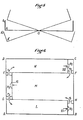
- La figure 1 est une vue en élévation d'un vaisseau simple pris dans la houle.
- La figure 2 est une vue schématique en coupe verticale longitudinale d'une autre version de vaisseau avec des cloches en proue et en poupe et avec des compartiments de machine au centre.
- La figure 3 est une vue schématique coupée suivant un plan horizontal d'un vaisseau comme celui de la figure 3.
- La figure 4 est une vue schématique du mouvement d'oscillation du vaisseau représenté à la figure 3.
- La figure 5 est une représentation schématique du mouvement du vaisseau représenté à la figure 6.
- La figure 6 est une vue schématique en coupe horizontale d'une deuxième version du vaisseau dans lequel on assigne au liquide d'entraînement des turbines un circuit.
- La figure 7 est une coupe verticale d'un vaisseau équipé d'une masse de contrôle de l'amplitude du tangage.
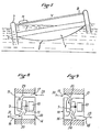
- La figure 8 est une vue schématique d'un compartiment à machines dans un premier sens d'écoulement du liquide.
- La figure 9 est une vue schématique du même compartiment de machines qu'à la figure 8 dans l'autre sens d'écoulement du liquide.
- Figure 1 is an elevational view of a single vessel caught in the swell.
- Figure 2 is a schematic view in longitudinal vertical section of another version of vessel with bells in bow and stern and with machine compartments in the center.
- FIG. 3 is a schematic view cut along a horizontal plane of a vessel like that of FIG. 3.
- FIG. 4 is a schematic view of the oscillation movement of the vessel shown in FIG. 3.
- FIG. 5 is a schematic representation of the movement of the vessel represented in FIG. 6.
- Figure 6 is a schematic horizontal sectional view of a second version of the vessel in which one assigns to the turbine drive liquid a circuit.
- Figure 7 is a vertical section of a vessel equipped with a mass for controlling the amplitude of the pitch.
- FIG. 8 is a schematic view of a machine compartment in a first direction of flow of the liquid.
- Figure 9 is a schematic view of the same machine compartment as in Figure 8 in the other direction of liquid flow.
On connaît des turbines travaillant sous une faible hauteur de chute en absorbant un grand débit avec de hauts rendements et qui entraînent des alternateurs avec une régularité suffisante.Turbines are known which work under a low head while absorbing a large flow rate with high yields and which drive alternators with sufficient regularity.
L'ensemble est monté sur un bateau qui peut être un navire, un ponton ou un engin flottant quelconque. Il doit être puissant, solide, pouvant résister aux tempêtes les plus violentes et évoluer par ses propres moyens.The assembly is mounted on a boat which can be any ship, pontoon or floating device. It must be powerful, solid, able to withstand the most severe storms and evolve on its own.
Il est mouillé, embossé avec touées longues, pour l'orienter, dans un site où la houle est constante et assez forte.It is wet, embossed with long strokes, to orient it, in a site where the swell is constant and fairly strong.
Il a des caractéristiques spécifiques variables suivant la houle qu'il a à connaître, mais en général et sans qu'elles soient limitatives, elles sont définies comme suit :It has specific characteristics which vary according to the swell it has to know, but in general and without being limiting, they are defined as follows:
Le tangage normal, maximum d'un bateau est obtenu lorsque sa longueur, à la ligne de flottaison, est égale à la longueur d'onde de la houle. Mais celle-ci varie. Pour l'exploiter au mieux on prend une carène à forte tonture. Le fond est un segment de cylindre de grand diamètre, parallèle à la houle, il tangue sans contrainte. La courbe est telle qu'elle peut épouser des houles de longueurs d'onde très différentes et ne rester qu'exceptionnellement en équilibre sur trois crêtes (figure 1).The normal, maximum pitch of a boat is obtained when its length, at the waterline, is equal to the wavelength of the swell. But this varies. To make the most of it, we take a hull with a large sheer. The bottom is a large diameter cylinder segment, parallel to the swell, it pitched without constraint. The curve is such that it can marry swells of very different wavelengths and only exceptionally remain in equilibrium on three peaks (Figure 1).
La largeur du vaisseau est fonction de la puissance désirée. Il est conçu pour garder sa stabilité en toutes circonstances. Le centre de gravité est maintenu assez haut pour favoriser le tangage. La position peut être modifiée par ballast, pour augmenter ou diminuer la longueur du bateau à la ligne de flottaison suivant la houle. Dans les limites d'une stabilité parfaite, calculée avec charges mobiles, les oeuvres vives sont réduites. Les oeuvres mortes sont importantes, car le déplacement, en quelques secondes, du fluide moteur de plusieurs milliers de tonnes provoque un enfoncement important. Il doit se relever aisément et rapidement. Pour cela, et éviter d'enfoncer, on prolonge la proue et la poupe largement et à chacune de ses extrémités on fixe des cloches C, C' à air ouvertes en bas (qui restent toujours immergées). A chaque coup de tangage, la pression monte dans les cloches C, C' et suivant que l'on ferme ou qu'on ouvre les vannes d'aspiration ou de décharge, situées à la partie supérieure, on contrôle l'enfoncement et le relevage. La manoeuvre se fait automatiquement par tout ou rien sur un certain nombre de cloches représentées entre A et D ainsi qu'entre C et F (figure 3).The width of the vessel depends on the desired power. It is designed to keep its stability in all circumstances. The center of gravity is kept high enough to encourage pitching. The position can be modified by ballast, to increase or decrease the length of the boat at the waterline depending on the swell. Within the limits of perfect stability, calculated with moving loads, the live works are reduced. Dead works are important, because the displacement, in a few seconds, of the working fluid of several thousand tons causes a significant depression. He must get up easily and quickly. To do this, and avoid sinking, we extend the bow and the stern widely and at each of its ends we attach air bells C, C 'open at the bottom (which always remain submerged). Each time the pitch is hit, the pressure rises in the bells C, C 'and depending on whether the suction or discharge valves located at the top are closed or opened, the sinking and lifting. The maneuver is done automatically by all or nothing on a certain number of bells represented between A and D as well as between C and F (figure 3).
Le volume des cloches C, C' est calculé d'après la charge mobile du bateau.The volume of the bells C, C 'is calculated according to the mobile load of the boat.
L'aménagement intérieur comporte : (figure 2)
- - un pont supérieur (23) avec tout le matériel de sécurité, de navigation, et de bonne tenue au mouillage.
- - un ou plusieurs ponts intermédiaires (24), (25) supportant les fluides moteurs, qui peuvent être différents. Le plus haut (24) pourrait contenir de l'eau de mer à envoyer dehors en cas de besoin. Un deuxième (25) contient un fluide dense à récupérer dans des citernes (22) situées à fond de cale et constituant ainsi un bon lest.
- - an upper deck (23) with all the safety, navigation and good anchorage equipment.
- - one or more intermediate bridges (24), (25) supporting the working fluids, which may be different. The upper one (24) could contain seawater to be sent outside if necessary. A second (2 5) contains a dense fluid to be recovered in tanks (22) situated in the hold and thus constituting a good ballast.
On prévoit, de chaque côté, une ou deux roues à aubes H, actionnées par le courant marin et produisant de l'élec- tricité pour les besoins du bord. Ces roues sont réversibles ; devenues motrices, elles servent pour des déplacements et évitages éventuels, notamment pour se placer face à la houle.Is provided, on each side, one or two impellers H actuated by the ocean current and producing t elec- ricité for the purposes of the edge. These wheels are reversible; become motive, they are used for displacements and possible avoidances, in particular to be placed facing the swell.
On prévoit aussi au moins un propulseur de poupe susceptible de faire éviter le vaisseau sur un bord ou sur l'autre.There is also at least one stern thruster capable of making the vessel avoid on one side or the other.
Des cloisons longitudinales K empêchent un écoulement des fluides sur le côté et le danger de gîte importante ou chavirement.Longitudinal partitions K prevent a flow of fluids on the side and the danger of significant heeling or capsizing.
Le fluide moteur se déplace donc de l'avant à l'arrière et revient. Les roues ou les turbines peuvent être placées au milieu de la salle (figure 3) ou aux extrémités (figure 6). (14) indique des compartiments à machines au milieu de la salle.The engine fluid therefore moves from front to rear and returns. The wheels or the turbines can be placed in the middle of the room (figure 3) or at the ends (figure 6). (14) indicates machine compartments in the middle of the room.
L'enfoncement étant du côté AD (figure 3), le liquide occupe le volume A'A1B/AD, position I à la figure 4. L'onde arrivant, le liquide s'élève et coule dans l'espace C"C1B/CF (Position 2 de la figure 4 et figure 3), en passant sur l'espace BEB'E' où sont installés les compartiments (14) des turbines (9). Il revient en position I et ainsi de suite en actionnant les turbines (9) à chaque passage.The depression being on the AD side (Figure 3), the liquid occupies the volume A'A1B / AD , position I in Figure 4. The incoming wave, the liquid rises and flows in the space C "C 1 B / CF (
Pour mieux comprendre ce fonctionnement, on se reportera aux figures 8 et 9 et à ce qui suit.To better understand this operation, reference is made to FIGS. 8 and 9 and the following.
Quand le côté de A est enfoncé, l'eau arrive suivant la flèche (28) (figure 8) en poussant le clapet (17) ouvert et en fermant les clapets (15) et (18). Elle passe donc, suivant la flèche (29), dans la turbine (9) qui entraîne la génératrice (10) par l'arbre (11). Elle s'échappe suivant les flèches (30) et (31) en ouvrant le clapet (16). Quand le côté de B est enfoncé, l'eau arrive suivant la flèche (32) (figure 9) en poussant le clapet (15) à l'ouverture et en fermant les clapets (16) et (17). Elle passe donc, suivant la flèche (33), dans la turbine (9) qui entraîne la génératrice (10) par l'arbre (11). Elle s'échappe suivant les flèches (34) et (35) en ouvrant le clapet (18). Les extrémités des planchers comportent des arrondis ou déflecteurs (12), (13) (figure 2) pour éviter le choc sur les murs et favoriser la montée. On augmente ainsi la hauteur de chute maximum "h". La hauteur de chute moyenne étant "h'".When the side of A is pressed, the water arrives along the arrow (28) (Figure 8) by pushing the valve (17) open and closing the valves (15) and (18). It therefore passes, along the arrow (29), in the turbine (9) which drives the generator (10) through the shaft (11). It escapes according to the arrows (30) and (31) by opening the valve (16). When the side of B is depressed, the water arrives along the arrow (32) (FIG. 9) by pushing the valve (15) at the opening and closing the valves (16) and (17). It therefore passes, along the arrow (33), in the turbine (9) which drives the generator (10) through the shaft (11). It escapes according to the arrows (34) and (35) by opening the valve (18). The ends of the floors have rounded or deflectors (12), (13) (Figure 2) to avoid impact on the walls and promote the rise. This increases the maximum fall height "h". The average fall height being "h '".
La figure 3 schématise un niveau. C'est un rectangle, mais ce peut être un polygone - deux trapèzes unis par leur grande base, ou même un losange. Pour un même volume, le liquide s'élève plus haut en haut de course, il en résulte une vitesse plus grande à l'entrée des turbines. La valeur de "h" varie, mais plusieurs dispositifs simples et ceux déjà bien connus permettent de faire tourner les turbines toujours dans le même sens et de régulariser leurs vitesses pour entraîner directement des alternateurs. Cela peut se faire par éclusage et maintien d'une réserve de liquide en BEB'E' (figure 3).Figure 3 shows a level diagram. It is a rectangle, but it can be a polygon - two trapezoids joined by their large base, or even a rhombus. For the same volume, the liquid rises higher at the top of the stroke, resulting in a greater speed at the inlet of the turbines. The value of "h" varies, but several simple devices and those already well known make it possible to rotate the turbines always in the same direction and to regulate their speeds to drive the alternators directly. This can be done by locking and maintaining a reserve of liquid in BEB'E '(Figure 3).
On peut aussi placer les turbines près des extrémités de la salle (figure 6). Dans ce cas, la hauteur de chute est plus grande. La vitesse du fluide à l'entrée des turbines est plus élevée que dans le cas précédent, mais n'est pas le double, car "v" varie comme V
Les réservoirs R1, R23 R3 ne sont jamais complètement vides. Les écluses ou clapets (19), (20), (21) étant bien réglés, les turbines tournent normalement.The tanks R 1 , R 23 R 3 are never completely empty. The locks or valves (19), (20), (21) being properly adjusted, the turbines rotate normally.
Sur le schéma, on a figuré quatre turbines en place. On peut en mettre beaucoup plus, deux ou trois par groupe, soit huit ou douze par ligne, suivant l'importance de fluide.The diagram shows four turbines in place. We can put a lot more, two or three per group, or eight or twelve per line, depending on the amount of fluid.
On peut aussi installer deux à trois lignes de turbines avec trois compartiments par ligne sur un bateau assez grand.We can also install two to three turbine lines with three compartments per line on a fairly boat tall.
Quelques exemples chiffrés donnent une idée des puissances importantes que l'on peut obtenir et maîtriser par ce procédé.Some numerical examples give an idea of the important powers that can be obtained and controlled by this process.
Figure 3 : AC = 60 m AB = 25 m AD = 60 mFigure 3: AC = 60 m AB = 25 m AD = 60 m
houle : longueur d'onde 50 m, creux 4 m, période 6 secondes. swell: wavelength 50 m, dip 4 m, period 6 seconds.
Figure 4 : enfoncement A'A'1 = h = 8 m.Figure 4: depression A'A ' 1 = h = 8 m.
Deux enfoncements par période, un à l'avant, un à l'arrière soit une toutes les trois secondes.Two push-ins per period, one at the front, one at the back, i.e. one every three seconds.
Le liquide occupe le volume : surface du triangle A'A'1B multiplié par la largeur AD. Soit : SA'A'1B x AD =![]()
![]()
Quand la proue se relève on admet que la hauteur moyenne h' du liquide engendrant la vitesse soit égale à 4 mètres. C'est un minimum ; on l'adoptera dans tous les cas.
Le fluide est de l'eau d = 1.![]()
![]()
- Si on emploie de l'eau de mer (d = 1,025)
- P2 = 81,35 MW
- Si le fluide est de l'eau-mère de marais salants (d = 1,320)
- P3 = 136,66 MW
- Si le fluide est une solution concentrée de CO3K2 (d = 1,500)
- P4 = 176,5 MW
The fluid is water d = 1.
- If seawater is used (d = 1.025)
- P2 = 81.3 5 MW
- If the fluid is mother water from salt marshes (d = 1,320)
- P 3 = 136.66 MW
- If the fluid is a concentrated solution of CO 3 K 2 (d = 1,500)
- P 4 = 176.5 MW
![]()
![]()
![]()
![]()
![]()

![]()
![]()
![]()
![]()
![]()
![]()
![]()
![]()
![]()
![]()
![]()
![]()
![]()
![]()
![]()
Claims (11)
les turbines T1, T2, T3, T4 étant disposées à la sortie de chaque compartiment de stockage R1, R2, R3, et de larges clapets (19), (20), (21) étant prévus en bout de chaque compartiment de transfert N, M, L et à l'entrée de chaque compartiment de stockage R1, R2, R3 pour assurer toujours le même sens de rotation du liquide dans le circuit.9. Device as defined in claim 1, characterized in that a circuit passing through:.
the turbines T 1 , T 2 , T 3 , T 4 being arranged at the outlet of each storage compartment R 1 , R 2 , R 3 , and large valves (19), (20), (21) being provided in end of each transfer compartment N, M, L and at the entrance to each storage compartment R 1 , R 2 , R 3 to always ensure the same direction of rotation of the liquid in the circuit.
Applications Claiming Priority (2)
| Application Number | Priority Date | Filing Date | Title |
|---|---|---|---|
| FR8104375A FR2500887A1 (en) | 1981-02-27 | 1981-02-27 | DEVICE FOR USING WAVE AND WAVE ENERGY |
| FR8104375 | 1981-02-27 |
Publications (1)
| Publication Number | Publication Date |
|---|---|
| EP0059652A1 true EP0059652A1 (en) | 1982-09-08 |
Family
ID=9255873
Family Applications (1)
| Application Number | Title | Priority Date | Filing Date |
|---|---|---|---|
| EP82400171A Withdrawn EP0059652A1 (en) | 1981-02-27 | 1982-02-02 | Wave energy harnessing device |
Country Status (5)
| Country | Link |
|---|---|
| US (1) | US4392061A (en) |
| EP (1) | EP0059652A1 (en) |
| BE (1) | BE892059A (en) |
| FR (1) | FR2500887A1 (en) |
| IT (1) | IT1154481B (en) |
Cited By (7)
| Publication number | Priority date | Publication date | Assignee | Title |
|---|---|---|---|---|
| GB2154668A (en) * | 1984-02-22 | 1985-09-11 | Silva Costa Manuel Da | A wave motion-operated marine engine |
| WO1993015315A1 (en) * | 1992-01-28 | 1993-08-05 | Francis Norman Potter | Power generation, preferably by utilisation of wave energy |
| FR2941016A1 (en) * | 2009-01-13 | 2010-07-16 | Georges Hildebrand | FLOATING CENTRAL FLOATING TRIPOD CENTRIFUGAL CONVERTING DIRECTLY IN ELECTRICITY THE PHENOMENON OF ROTULATING CREATED BY THE HOLES. |
| WO2013160617A3 (en) * | 2012-04-25 | 2014-03-06 | Geps Innov | Energy recovery device |
| WO2016042236A1 (en) | 2014-09-18 | 2016-03-24 | Geps Techno | Energy generation on a structure subject to swell |
| WO2016042235A1 (en) * | 2014-09-18 | 2016-03-24 | Geps Techno | Device and method for a structure subject to oscillating movements |
| FR3026148A1 (en) * | 2014-09-18 | 2016-03-25 | Geps Techno | DEVICE AND METHOD FOR CONTROLLING OSCILLATIONS OF A SHIP SUBMITTED TO THE WAVE. |
Families Citing this family (27)
| Publication number | Priority date | Publication date | Assignee | Title |
|---|---|---|---|---|
| IT1139379B (en) * | 1981-08-18 | 1986-09-24 | Tecnomare Spa | SYSTEM FOR THE RECOVERY OF THE ENERGY OF THE WAVE MOTOR AND ITS TRANSFORMATION INTO USEFUL ENERGY |
| DE3822680A1 (en) * | 1988-07-05 | 1990-01-18 | Franz Osterkamp | DEVICE FOR THE PRODUCTION OF ELECTRICAL ENERGY |
| JP2549896B2 (en) * | 1988-09-21 | 1996-10-30 | 有限会社 パラサイト | Multiple gas phase tidal power generator |
| US9976535B2 (en) * | 2005-11-07 | 2018-05-22 | Gwave Llc | System for producing energy through the action of waves |
| US8519557B2 (en) * | 2005-11-07 | 2013-08-27 | Gwave Llc | System for producing energy through the action of waves |
| WO2007056282A2 (en) * | 2005-11-07 | 2007-05-18 | Glenn Beane | System for producing electricity through the action of waves on floating platforms |
| US8915078B2 (en) * | 2005-11-07 | 2014-12-23 | Gwave Llc | System for producing energy through the action of waves |
| US7755224B2 (en) * | 2005-11-07 | 2010-07-13 | Glenn Beane | System for producing electricity through the action of waves on floating platforms |
| US8701403B2 (en) * | 2005-11-07 | 2014-04-22 | Gwave Llc | System for producing energy through the action of waves |
| ES2304278B1 (en) * | 2006-01-03 | 2009-07-27 | Juan Reyes Florido | SYSTEM FOR THE USE OF THE FORCE OF GRAVITY. |
| US8207622B2 (en) * | 2008-02-20 | 2012-06-26 | Knowledge Based Systems, Inc. | Inertial mass power generation |
| US8359855B1 (en) * | 2008-05-12 | 2013-01-29 | Marcel Fagan | Waves and sea swells imitator apparatus |
| US8901766B2 (en) * | 2008-06-12 | 2014-12-02 | Alexander K. Werjefelt | Wave action electric generating system including a boom on a floating platform |
| US20100171311A1 (en) * | 2009-01-06 | 2010-07-08 | Edmund Albert Eckart | Wave power generator |
| US20100230964A1 (en) * | 2009-03-10 | 2010-09-16 | Sachs George A | Adaptive Nacelle Support Systems, and Methods, for Wave Energy Conversion |
| US20100283249A1 (en) * | 2009-05-07 | 2010-11-11 | Phillip Harden | System and method for conversion of ocean waves into usable mechanical energy |
| CA2771341C (en) * | 2009-08-19 | 2017-10-10 | Alexander Werjefelt | Wave action electric generating system |
| GB2473659B (en) * | 2009-09-19 | 2012-04-11 | Bruce Gregory | Dynamically tuned wave energy conversion system |
| TWM381681U (en) * | 2010-01-12 | 2010-06-01 | shi-xiong Chen | Seesaw type water wave electric generator |
| GB2483270A (en) * | 2010-09-02 | 2012-03-07 | Ian Thaxter | Buoyant wave energy converter |
| FR2966886B1 (en) * | 2010-10-27 | 2012-11-16 | Mathieu Barsacq | ENERGY RECOVERY DEVICE |
| SE536349C2 (en) * | 2011-03-14 | 2013-09-03 | Rickard Nilsson | Device and method for converting wave power to electrical energy |
| PE20150225A1 (en) | 2012-06-04 | 2015-02-22 | Gwave Llc | ENERGY PRODUCTION SYSTEM THROUGH THE ACTION OF WAVES |
| US20160160844A1 (en) * | 2012-11-16 | 2016-06-09 | John A. Saavedra | Apparatus and method for generating electricity |
| WO2014120399A2 (en) * | 2013-02-01 | 2014-08-07 | Costas Dan N | Apparatus for converting wave energy |
| SE540263C2 (en) * | 2016-06-13 | 2018-05-15 | Novige Ab | Apparatus for harvesting energy from waves |
| PT3721072T (en) * | 2017-12-06 | 2022-01-28 | Massachusetts Inst Technology | System for generating electrical energy from the wave motion of the sea |
Citations (4)
| Publication number | Priority date | Publication date | Assignee | Title |
|---|---|---|---|---|
| FR455456A (en) * | 1913-03-08 | 1913-08-01 | James Drayton Mcfarland Junior | Method and apparatus for transforming wave motion into usable mechanical energy |
| GB557049A (en) * | 1941-08-04 | 1943-11-02 | Bernard Leo Rosenstengel | Improvements in and relating to apparatus for producing power |
| FR2375463A1 (en) * | 1976-12-22 | 1978-07-21 | Scarpi Bruno | SWELL ENERGY RECOVERY METHOD AND IMPLEMENTATION DEVICE |
| FR2455193A1 (en) * | 1979-04-26 | 1980-11-21 | Rodriguez Andre | Wave power generating device - includes rocking hull in which water is lifted on sloping shelves, with water rising through one stage during each cycle |
Family Cites Families (6)
| Publication number | Priority date | Publication date | Assignee | Title |
|---|---|---|---|---|
| US4009396A (en) * | 1975-11-19 | 1977-02-22 | Mattera Henry A | Wave operated power plant |
| FR2435387A2 (en) * | 1976-06-30 | 1980-04-04 | Rinaldi Victor | Semi-submersible wave energy converter - has toroidal vessel oscillating to generate hydropneumatic energy for electrical generator |
| FR2436070A2 (en) * | 1976-06-30 | 1980-04-11 | Rinaldi Victor | Sea wave energy converter - uses semi-submerged hollow toroidal vessel contg. e.g. rotatable wheel driving electric generator |
| US4110630A (en) * | 1977-04-01 | 1978-08-29 | Hendel Frank J | Wave powered electric generator |
| US4123185A (en) * | 1977-06-06 | 1978-10-31 | Hagen Alf R | Floating breakwater and energy collecting system |
| US4179886A (en) * | 1977-11-08 | 1979-12-25 | Junjiro Tsubota | Method and apparatus for obtaining useful work from wave energy |
-
1981
- 1981-02-27 FR FR8104375A patent/FR2500887A1/en active Granted
-
1982
- 1982-02-02 EP EP82400171A patent/EP0059652A1/en not_active Withdrawn
- 1982-02-09 BE BE2/59571A patent/BE892059A/en not_active IP Right Cessation
- 1982-02-25 IT IT67206/82A patent/IT1154481B/en active
- 1982-03-01 US US06/353,104 patent/US4392061A/en not_active Expired - Fee Related
Patent Citations (4)
| Publication number | Priority date | Publication date | Assignee | Title |
|---|---|---|---|---|
| FR455456A (en) * | 1913-03-08 | 1913-08-01 | James Drayton Mcfarland Junior | Method and apparatus for transforming wave motion into usable mechanical energy |
| GB557049A (en) * | 1941-08-04 | 1943-11-02 | Bernard Leo Rosenstengel | Improvements in and relating to apparatus for producing power |
| FR2375463A1 (en) * | 1976-12-22 | 1978-07-21 | Scarpi Bruno | SWELL ENERGY RECOVERY METHOD AND IMPLEMENTATION DEVICE |
| FR2455193A1 (en) * | 1979-04-26 | 1980-11-21 | Rodriguez Andre | Wave power generating device - includes rocking hull in which water is lifted on sloping shelves, with water rising through one stage during each cycle |
Cited By (14)
| Publication number | Priority date | Publication date | Assignee | Title |
|---|---|---|---|---|
| GB2154668A (en) * | 1984-02-22 | 1985-09-11 | Silva Costa Manuel Da | A wave motion-operated marine engine |
| WO1993015315A1 (en) * | 1992-01-28 | 1993-08-05 | Francis Norman Potter | Power generation, preferably by utilisation of wave energy |
| FR2941016A1 (en) * | 2009-01-13 | 2010-07-16 | Georges Hildebrand | FLOATING CENTRAL FLOATING TRIPOD CENTRIFUGAL CONVERTING DIRECTLY IN ELECTRICITY THE PHENOMENON OF ROTULATING CREATED BY THE HOLES. |
| WO2010081961A1 (en) * | 2009-01-13 | 2010-07-22 | Georges Hildebrand | Device for recovering sea wave energy |
| US9410538B2 (en) | 2012-04-25 | 2016-08-09 | Geps Innov | Energy recovering device |
| WO2013160617A3 (en) * | 2012-04-25 | 2014-03-06 | Geps Innov | Energy recovery device |
| WO2016042236A1 (en) | 2014-09-18 | 2016-03-24 | Geps Techno | Energy generation on a structure subject to swell |
| WO2016042235A1 (en) * | 2014-09-18 | 2016-03-24 | Geps Techno | Device and method for a structure subject to oscillating movements |
| FR3026148A1 (en) * | 2014-09-18 | 2016-03-25 | Geps Techno | DEVICE AND METHOD FOR CONTROLLING OSCILLATIONS OF A SHIP SUBMITTED TO THE WAVE. |
| FR3026147A1 (en) * | 2014-09-18 | 2016-03-25 | Geps Techno | DEVICE FOR PRODUCING ENERGY ON A SHIP SUBMITTED TO COOL |
| CN107002629A (en) * | 2014-09-18 | 2017-08-01 | Geps泰克诺公司 | For the apparatus and method for the structure for being subjected to oscillating motion |
| RU2689640C2 (en) * | 2014-09-18 | 2019-05-28 | Джепс Текно | Method and device for a structure subject to rolling |
| US10414471B2 (en) | 2014-09-18 | 2019-09-17 | Geps Techno | Device and method for a structure subject to oscillating movements |
| CN107002629B (en) * | 2014-09-18 | 2019-11-05 | Geps泰克诺公司 | Device and method for being subjected to the structure of pendulum motion |
Also Published As
| Publication number | Publication date |
|---|---|
| BE892059A (en) | 1982-05-27 |
| IT8267206A0 (en) | 1982-02-25 |
| US4392061A (en) | 1983-07-05 |
| FR2500887A1 (en) | 1982-09-03 |
| FR2500887B1 (en) | 1984-10-05 |
| IT1154481B (en) | 1987-01-21 |
Similar Documents
| Publication | Publication Date | Title |
|---|---|---|
| EP0059652A1 (en) | Wave energy harnessing device | |
| EP2140135B1 (en) | Device and method for collecting the kinetic energy of a naturally moving fluid | |
| US7928594B2 (en) | Apparatus for receiving and transferring kinetic energy from a flow and wave | |
| US8696301B2 (en) | Apparatus for extracting energy from flowing water | |
| US20060019553A1 (en) | Method and apparatus for retrieving energy from a flowing stream of water | |
| US4123185A (en) | Floating breakwater and energy collecting system | |
| JP5486600B2 (en) | Fluid generator | |
| US10100803B1 (en) | Ocean wave-crest powered electrical generator in combination with pumped storage | |
| FR2465838A1 (en) | DEVICE FOR USING WAVE ENERGY | |
| FR2852063A1 (en) | Wind turbine for generating wind energy, has set of propellers surrounded by streamline shroud which includes high, low and lateral panels to canalize wind towards propellers in open position | |
| WO2008068390A1 (en) | Wave energy recovery device | |
| FR2981992A1 (en) | Device for recuperating energy of e.g. oscillation movement of earth tremor, in form of electric energy, has adjustable stopper arranged at level of throttling channel for utilized for passage of liquid contained in container | |
| WO2008084262A2 (en) | Power generation means | |
| EP2547899B1 (en) | Device for recovering wave energy and corresponding method | |
| WO2018127630A1 (en) | Wind turbine or water turbine with vortex effect and sequence for outer lateral compression-tilting-ejection of an incident fluid, facing the impeller | |
| EP3707371B1 (en) | Floating hydroelectric power plant for shallow rivers | |
| KR20230053690A (en) | Wave-energized diode pump | |
| EP1700032A1 (en) | Floating device for recovery of swell energy with a spiral lift | |
| EP3101269B1 (en) | System for generating energy from ocean wave motion | |
| GB2419383A (en) | Endless loop wave generation device and marine propulsion unit | |
| FR2908479A1 (en) | Wave energy collecting device for producing electric energy, has pivot to orient platform housing annexed installations, motivators comprising energy transformation system at front of platform, and cable passing through pivot or trunnion | |
| WO2024042453A1 (en) | Offshore apparatus for extracting energy from a fluid and methods for its use | |
| FR3026442A1 (en) | WAVE ENERGY RECOVERY SYSTEM | |
| FR3026147A1 (en) | DEVICE FOR PRODUCING ENERGY ON A SHIP SUBMITTED TO COOL | |
| FR3013029A1 (en) |
Legal Events
| Date | Code | Title | Description |
|---|---|---|---|
| PUAI | Public reference made under article 153(3) epc to a published international application that has entered the european phase |
Free format text: ORIGINAL CODE: 0009012 |
|
| AK | Designated contracting states |
Designated state(s): DE GB NL |
|
| STAA | Information on the status of an ep patent application or granted ep patent |
Free format text: STATUS: THE APPLICATION IS DEEMED TO BE WITHDRAWN |
|
| 18D | Application deemed to be withdrawn |
Effective date: 19830815 |