EP0058645A1 - Infrared radiation detector device - Google Patents
Infrared radiation detector device Download PDFInfo
- Publication number
- EP0058645A1 EP0058645A1 EP82830027A EP82830027A EP0058645A1 EP 0058645 A1 EP0058645 A1 EP 0058645A1 EP 82830027 A EP82830027 A EP 82830027A EP 82830027 A EP82830027 A EP 82830027A EP 0058645 A1 EP0058645 A1 EP 0058645A1
- Authority
- EP
- European Patent Office
- Prior art keywords
- metal
- infrared radiation
- detection
- vacuum
- feed
- Prior art date
- Legal status (The legal status is an assumption and is not a legal conclusion. Google has not performed a legal analysis and makes no representation as to the accuracy of the status listed.)
- Granted
Links
- 230000005855 radiation Effects 0.000 title claims abstract description 24
- 238000001514 detection method Methods 0.000 claims abstract description 19
- 229910052751 metal Inorganic materials 0.000 claims description 43
- 239000002184 metal Substances 0.000 claims description 43
- 238000000034 method Methods 0.000 claims description 21
- 239000000758 substrate Substances 0.000 claims description 12
- 239000000919 ceramic Substances 0.000 claims description 11
- 230000008569 process Effects 0.000 claims description 9
- 229910000833 kovar Inorganic materials 0.000 claims description 6
- 229910045601 alloy Inorganic materials 0.000 claims description 5
- 239000000956 alloy Substances 0.000 claims description 5
- 238000005219 brazing Methods 0.000 claims description 5
- 239000011521 glass Substances 0.000 claims description 5
- 238000003466 welding Methods 0.000 claims description 5
- 229910001092 metal group alloy Inorganic materials 0.000 claims 3
- 238000010521 absorption reaction Methods 0.000 claims 1
- 238000005476 soldering Methods 0.000 claims 1
- 238000004519 manufacturing process Methods 0.000 abstract description 11
- 239000000306 component Substances 0.000 description 27
- 230000008901 benefit Effects 0.000 description 8
- 238000001465 metallisation Methods 0.000 description 6
- PXHVJJICTQNCMI-UHFFFAOYSA-N Nickel Chemical compound [Ni] PXHVJJICTQNCMI-UHFFFAOYSA-N 0.000 description 5
- PNEYBMLMFCGWSK-UHFFFAOYSA-N aluminium oxide Inorganic materials [O-2].[O-2].[O-2].[Al+3].[Al+3] PNEYBMLMFCGWSK-UHFFFAOYSA-N 0.000 description 3
- 238000010276 construction Methods 0.000 description 3
- 238000001816 cooling Methods 0.000 description 3
- 230000005693 optoelectronics Effects 0.000 description 3
- RYGMFSIKBFXOCR-UHFFFAOYSA-N Copper Chemical compound [Cu] RYGMFSIKBFXOCR-UHFFFAOYSA-N 0.000 description 2
- 229910052802 copper Inorganic materials 0.000 description 2
- 239000010949 copper Substances 0.000 description 2
- 238000013461 design Methods 0.000 description 2
- 238000004801 process automation Methods 0.000 description 2
- 239000004065 semiconductor Substances 0.000 description 2
- WFKWXMTUELFFGS-UHFFFAOYSA-N tungsten Chemical compound [W] WFKWXMTUELFFGS-UHFFFAOYSA-N 0.000 description 2
- 229910052721 tungsten Inorganic materials 0.000 description 2
- 239000010937 tungsten Substances 0.000 description 2
- 241000587161 Gomphocarpus Species 0.000 description 1
- 229910000661 Mercury cadmium telluride Inorganic materials 0.000 description 1
- QVYYOKWPCQYKEY-UHFFFAOYSA-N [Fe].[Co] Chemical compound [Fe].[Co] QVYYOKWPCQYKEY-UHFFFAOYSA-N 0.000 description 1
- 238000000429 assembly Methods 0.000 description 1
- 230000000712 assembly Effects 0.000 description 1
- MCMSPRNYOJJPIZ-UHFFFAOYSA-N cadmium;mercury;tellurium Chemical compound [Cd]=[Te]=[Hg] MCMSPRNYOJJPIZ-UHFFFAOYSA-N 0.000 description 1
- 238000006243 chemical reaction Methods 0.000 description 1
- YCKOAAUKSGOOJH-UHFFFAOYSA-N copper silver Chemical compound [Cu].[Ag].[Ag] YCKOAAUKSGOOJH-UHFFFAOYSA-N 0.000 description 1
- 230000007423 decrease Effects 0.000 description 1
- 230000007547 defect Effects 0.000 description 1
- 230000001419 dependent effect Effects 0.000 description 1
- 230000000694 effects Effects 0.000 description 1
- 238000009713 electroplating Methods 0.000 description 1
- 230000005496 eutectics Effects 0.000 description 1
- 238000010304 firing Methods 0.000 description 1
- 230000004907 flux Effects 0.000 description 1
- WPYVAWXEWQSOGY-UHFFFAOYSA-N indium antimonide Chemical compound [Sb]#[In] WPYVAWXEWQSOGY-UHFFFAOYSA-N 0.000 description 1
- 238000009776 industrial production Methods 0.000 description 1
- 238000003331 infrared imaging Methods 0.000 description 1
- 238000009413 insulation Methods 0.000 description 1
- 230000010354 integration Effects 0.000 description 1
- 238000011835 investigation Methods 0.000 description 1
- 229910052748 manganese Inorganic materials 0.000 description 1
- 239000011572 manganese Substances 0.000 description 1
- 239000000463 material Substances 0.000 description 1
- 150000002739 metals Chemical class 0.000 description 1
- VIKNJXKGJWUCNN-XGXHKTLJSA-N norethisterone Chemical compound O=C1CC[C@@H]2[C@H]3CC[C@](C)([C@](CC4)(O)C#C)[C@@H]4[C@@H]3CCC2=C1 VIKNJXKGJWUCNN-XGXHKTLJSA-N 0.000 description 1
- 238000007781 pre-processing Methods 0.000 description 1
- 238000012545 processing Methods 0.000 description 1
- CLKZWXHKFXZIMA-UHFFFAOYSA-N pyrinuron Chemical compound C1=CC([N+](=O)[O-])=CC=C1NC(=O)NCC1=CC=CN=C1 CLKZWXHKFXZIMA-UHFFFAOYSA-N 0.000 description 1
- 230000009467 reduction Effects 0.000 description 1
- 238000002310 reflectometry Methods 0.000 description 1
- 238000007650 screen-printing Methods 0.000 description 1
- 238000012216 screening Methods 0.000 description 1
- 239000010421 standard material Substances 0.000 description 1
- 238000012360 testing method Methods 0.000 description 1
- 238000001931 thermography Methods 0.000 description 1
Images


Classifications
-
- G—PHYSICS
- G01—MEASURING; TESTING
- G01J—MEASUREMENT OF INTENSITY, VELOCITY, SPECTRAL CONTENT, POLARISATION, PHASE OR PULSE CHARACTERISTICS OF INFRARED, VISIBLE OR ULTRAVIOLET LIGHT; COLORIMETRY; RADIATION PYROMETRY
- G01J5/00—Radiation pyrometry, e.g. infrared or optical thermometry
- G01J5/10—Radiation pyrometry, e.g. infrared or optical thermometry using electric radiation detectors
- G01J5/28—Radiation pyrometry, e.g. infrared or optical thermometry using electric radiation detectors using photoemissive or photovoltaic cells
-
- H—ELECTRICITY
- H01—ELECTRIC ELEMENTS
- H01B—CABLES; CONDUCTORS; INSULATORS; SELECTION OF MATERIALS FOR THEIR CONDUCTIVE, INSULATING OR DIELECTRIC PROPERTIES
- H01B17/00—Insulators or insulating bodies characterised by their form
- H01B17/26—Lead-in insulators; Lead-through insulators
- H01B17/30—Sealing
-
- H—ELECTRICITY
- H01—ELECTRIC ELEMENTS
- H01L—SEMICONDUCTOR DEVICES NOT COVERED BY CLASS H10
- H01L31/00—Semiconductor devices sensitive to infrared radiation, light, electromagnetic radiation of shorter wavelength or corpuscular radiation and specially adapted either for the conversion of the energy of such radiation into electrical energy or for the control of electrical energy by such radiation; Processes or apparatus specially adapted for the manufacture or treatment thereof or of parts thereof; Details thereof
- H01L31/02—Details
- H01L31/02002—Arrangements for conducting electric current to or from the device in operations
-
- H—ELECTRICITY
- H01—ELECTRIC ELEMENTS
- H01L—SEMICONDUCTOR DEVICES NOT COVERED BY CLASS H10
- H01L31/00—Semiconductor devices sensitive to infrared radiation, light, electromagnetic radiation of shorter wavelength or corpuscular radiation and specially adapted either for the conversion of the energy of such radiation into electrical energy or for the control of electrical energy by such radiation; Processes or apparatus specially adapted for the manufacture or treatment thereof or of parts thereof; Details thereof
- H01L31/02—Details
- H01L31/0203—Containers; Encapsulations, e.g. encapsulation of photodiodes
Definitions
- the herewith presented invention concerns a device for the detection of infrared radiation, comprising a photosensitive component which consists of an elevated number of elements operating at low temperatures and comprising a vacuum tight embodiment which is characterized by a very high electrical feed-through package density, low thermal loss, high compactness and ruggedness, low production costs and which offers a high degree of industrial standardization.
- An illustrative example is an infrared system for thermal imagery (FLIR) for military applications characterized by a number of 180 sensitive elements in linear configuration.
- FLIR infrared system for thermal imagery
- the cooling means is a 1 watt cryogenerator of closed-cycle type.
- An other illustrative example is a corrpact, hand-porta ble thermal viewer for military and industrial applications, featured by a number of about 50 sensitive elements in bidimensional configuration for serial-parallel scanning, and by an open-cycle Joule Thompson nini- cooler with less than 100 mwatt cooling power.
- examples 1 and 2 stand for a class of many infrared passive systems which have already reached an industrial production level, there is a world-wide effort to further improve overall system performances to satisfy requests for new applications and to reduce system production costs.
- the examples 3 thru 5 indicate the trends in infrared detectors namely increasing integration and complexity of the photosensitive semiconductor component in a similar way as it is typical for conventional semiconductor devices, along with miniaturization of the vacuum embodi ment component and lowering of its thermal power losses.
- the fig. 1 shows schematically the cross section of the device com prising infrared sensor array and vacuum-cryocontainer.
- the device is a combination of several parts which have been ordered in respect to their specific functions regarding detector construction and detector ope rative features.
- the detector body 1 (Fig. 1) consists of a glass part 1.1 with an inner "cold finger” tube 1.2 which is made of glass or of glass/metal and which is closed by the part 1.3 serving as thermal contact between the cooling means within the cold finger and the photosensitive component 3.1 within the vacuum vessel.
- the part 1.1 is externally sealed to a metal tube 1.4 which itself is connected with the metal tube 2.3 being part of the multi-feed-through package 2, by means of brazing or welding.
- the absoption getters 1.5 are incorporated in the body 1.
- the feed-through component is given by the elements 2.1 thru 2.5 of fig. 1.
- the element 2.1 comprises a ceramic substrate ring with a metalli zation ring on the lower surface, and a pattern of radial metal strip-line tracks on the upper surface.
- a ceramic insulating Layer is applied onto the centre part of the strip-line tracks which Layer provides an upper metallization ring.
- This ring and the metallization ring on the lower surface of the substrate are connected with the metal tubes 2.2 and 2.3, respectively.
- Each metal strip-line track provides a metal pin 2.4 of a length such as to have a co-planar position of the pin head in respect to the photosensitive component 3.1.
- the interconnection between the photosensitive component which is mounted on the disk 1.3 and the feed-through pattern is performed by means of thin wires of low thermal conductivity suited to commonly used micro-wire bonding techniques.
- the component 4 of fig. 1 consists of the infrared transparent window 4.2, hermetically sealed to a metal tube 4.1 which provides an edge for the final closure of the detector embodiment by means of welding connection of the two elements 4.1 and 2.2.
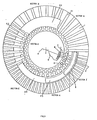
- the fig. 2 shows a cross section of the particularity of the assem bly of the vacuum feed-through component.
- the sector f gives an on plane view of the assembly of fig. 2 with the two corrisponding lines AA' (fig. 3) and BB' (fig. 2).
- the ceramic substrate 1 (fig. 2 and fig. 3, section a) is alumina.
- the first layer 2.1 of fig. 3 is a pattern of metal strip lines, ending in, for instance circular, dots. Metals which are typically applied are moly-manganese or tungsten.
- the following layer 2.2 of fig. 3 is insulating alumina.
- a second metal strip line pattern is applied (2.3, fig. 3) with the dots being electrically isolated from the first metal pattern plane, as indicated on sector c of the figure.
- Onto the sector c plane another insulation layer of alumina is applied (2.4, fig. 3) followed by a metal layer 2.5, fig. 3.
- a metallizating ring similar to the layer 2.5 of fig. 3 is applied to the rear surface of the substrate 1 as indicated on fig. 2.
- the complete multilayer structure is then sintered by a firing process at temperatures much higher than 1000°C. After this, all exposed metal surfaces are metal plated.
- the detector assembly is going to be completed by a next step of feed-through component construction.
- the metal pins 4 of fig. 2 and 3, for instance made of iron cobalt nichel alloys as Kovar R or Vaco R are nail-head brazed on the metal dots which are the inner terminals of the strip lines 2.1 and 2.3 of fig. 3 by means of for instance alloy preforms.
- the tubes 6 (fig. 2 and fig. 3) of for instance Kovar or Vacon are head brazed on the upper and rear metallizations (2.5) fig. 3).
- the brazing process with a preform 5 of copper silver eutectic together with OFHC grade copper is an often used technique.
- the multi-feed-through component as it is defined by the elements under point 2 of fig. 1 is ready for being assembled on the body component 1 of fig. 1, by connecting the elements 2. and 1.4 of fig. 1 for instance by means of arc welding.
- the terminals 8 are connected with the flat shaped heads of the pins 4 by round or rolled wires 7 with diameters of, for instance, from 25 microns to 50 corrisponding cross sections.
- the wire material is characterized by having such a low thermal conductivity as to reduce the thermal through-wire loss to sufficiently low value even with lengths of only a few millimeters or anyway, with lengths, short enough to be compatible with the very compact detector structure which offers small distances between the on-focal plane substrate 9 of fig. 2 and 3 and the metal connector pins 4.
- thermal power losses are less than 10 mWatt/per 100 elements, values which are negligible in respect to the total thermal loss of the detector.
- This configuration allows the use of standard, market available micro-bonding machines together with a high process automation suited to low cost production performed by unskilled personnel.
- the bonding process can be performed by means of Kovar gap-welding which is known as one of the most reliable interconnection techniques.
- the extending strip lines 1 of fig. 4 can be provided with metal pins or pads 2 which are brazed by means of an alloy 3 in the same way as the pin brazing process has been performed.
- a first advantage of the described structure is the extremely high . feed-through track pattern density. Using standard technological margins and tolerances, a strip-to-strip center pitch of less the 0.3 milli meters is easily achievable when using the double metal strip layer configuration of the above described example and further reductions are within the feasibility margins of the techniques of the state of the art.
- the multi-feed-through component being a separatedly constructed module is 100 percently tested before the assembly with the other compo nents of the device, accordingly to the specifications of the particular detector for which it is used.
- This in-process check eliminates rejects caused by defects in the feed-through package, revealed in an advanced stage of detector assembly and presents therefore a further advantage.
- Still another advantage lies in compactness and mechanical ruggedness of the described multilayer package together with the high reliabi lity of the sintered metal strip pattern.
- Thermal loss due to thermal conduction is practically limited to the heat flux through the cold finger walls with values which are essentially dictated by the type of the cooler and its technical requirements. Losses due to thermal radiation are reduced in the usual way to a minimum by wall metallization and by means of incorporated metal layers with low emissivity values, high reflectivity and low transversal thermal conducti vity. Thermal load due to the power dissipated by the infrared sensitive component or other electronic components depends on the type of the opto electronic converter component and is therefore not taken into account here except of the fact of having provided a good thermal contact between the inner wall of the cold finger top and the on focal plane assembled photosensitive component by means of the disk 1.3 of fig. 1.
- the detectivity performance often decreases with incrasing temperatures in the range above 8d degrees Kelvin.
- the lower limit of the outer diameter of the detector device is essentially determined by the diameter of the cold finger and hence by the type of the cooler which is a system requirement parameter.
- the outer diameter including the extending strip line pattern ring illustrated by 1 of fig. 4, results less than . 25 millimeters.
- thermoelectric cooler (example 3) it is trivial to say to have to substitute the "cold finger" by a heat sink, externally connected with the vacuum embodiment.
Landscapes
- Physics & Mathematics (AREA)
- General Physics & Mathematics (AREA)
- Engineering & Computer Science (AREA)
- Microelectronics & Electronic Packaging (AREA)
- Condensed Matter Physics & Semiconductors (AREA)
- Electromagnetism (AREA)
- Computer Hardware Design (AREA)
- Power Engineering (AREA)
- Spectroscopy & Molecular Physics (AREA)
- Photometry And Measurement Of Optical Pulse Characteristics (AREA)
- Light Receiving Elements (AREA)
Abstract
Description
- The herewith presented invention concerns a device for the detection of infrared radiation, comprising a photosensitive component which consists of an elevated number of elements operating at low temperatures and comprising a vacuum tight embodiment which is characterized by a very high electrical feed-through package density, low thermal loss, high compactness and ruggedness, low production costs and which offers a high degree of industrial standardization.
- Present-day systems for the detection of infrared radiation in the medium or far infrared regions and in particular, systems for thermal imaging or for passive surveillance in the infrared, require infrared detectors with an elevated number of sensitive elements with sensibility performances (detectivities) near the theoretical limit, which require operative temperature conditions of typically from 70° Kelvin to 190° Kelvin.
- An illustrative example (example 1) is an infrared system for thermal imagery (FLIR) for military applications characterized by a number of 180 sensitive elements in linear configuration.
- The cooling means is a 1 watt cryogenerator of closed-cycle type.
- An other illustrative example (example 2) is a corrpact, hand-porta ble thermal viewer for military and industrial applications, featured by a number of about 50 sensitive elements in bidimensional configuration for serial-parallel scanning, and by an open-cycle Joule Thompson nini- cooler with less than 100 mwatt cooling power.
- Whereas the examples 1 and 2 stand for a class of many infrared passive systems which have already reached an industrial production level, there is a world-wide effort to further improve overall system performances to satisfy requests for new applications and to reduce system production costs.
- An essential part of this activity is focalized on the infrared detector which is the centre component of any infrared passive system,
- The following examples should give an indication for some of the various lines directed to future systems.
- 1) Multielement detectors operating at temperatures which can be achieved by multi-stage thermoelectric (Peltier) coolers (example 3).
- The solid-state type cold generator is completely integrated with the optoelectronic converter component resulting thus in an extremely small, compact, thermally self-sufficient detector.
- The very low electro-thermal conversion efficiency requires an extremely low thermal power consumption and hence, an extremely high thermal decoupling between the on focal plane, cooled sensor and the detector ambient, i.e. the walls of the detector embodiment and the vacuum multi-feed-through structure.
- 2) Multielement detectors for applications in missiles of short and medium range which are equiped with infrared imaging heads (example 4). Because of the limited missile overall dimensions together with severe operative conditions, a particulary small and rugged detector is mandatory with a diameter which is essentially limited by the vacuum feed through package density.
- 3) Multielement detector (example 5) for applications as sketched under example 1, characterized by a linear or bidimensional photo sensitive component integrated on focal plane with part of the electronic signal processing circuitry in hybrid or monolithic version, and with the detector suited to a new generation of very small sized, lcw thermal power closed-cycle cryogenerators.
- The examples 3
thru 5 indicate the trends in infrared detectors namely increasing integration and complexity of the photosensitive semiconductor component in a similar way as it is typical for conventional semiconductor devices, along with miniaturization of the vacuum embodi ment component and lowering of its thermal power losses. - Under these aspects, the feed-throughcomponent of the detector de vice is of particulary problematic nature. Many technological solutions to this have been proposed and several of them have been applied for constructing reliable, high vacuum-tight feed-throughs for multielement infrared detectors. Amongst those, there is a particular version derived from the patents (ITALY: 49632-A/76, U.S.A.: 4.118.947, U.K.: 1.537.187) and characterized by a ceramic/metal/ ceramic overlay structure.
- On this particular version we have performed an extensive technological study.
- The results of which have led to the innovative detector configura tion which will be schematically described in the following and for which an illustrative concrete example will be given, aiming to demonstrate the advantages which this new configuration present. Another important feature is in production cost savings of multielement infrared detectors. Due to the variety of detector-to-system interfaces and the complexity of combining the very different technological fields involved, detector costs are still relatively very high in respect to other infrared system components with the costs for detector embodiment and the final assembly being a relevant part of total detector costs.
- The construction of the multielement infrared detector device with high feed-through package density and low thermal loss which device is subject of the invention, will now be described in detail with reference to the attached figures by giving a concrete example of a particular technological version which illustrates the general innovative concept,
- The fig. 1 shows schematically the cross section of the device com prising infrared sensor array and vacuum-cryocontainer. The device is a combination of several parts which have been ordered in respect to their specific functions regarding detector construction and detector ope rative features.
- The detector body 1 (Fig. 1) consists of a glass part 1.1 with an inner "cold finger" tube 1.2 which is made of glass or of glass/metal and which is closed by the part 1.3 serving as thermal contact between the cooling means within the cold finger and the photosensitive component 3.1 within the vacuum vessel. The part 1.1 is externally sealed to a metal tube 1.4 which itself is connected with the metal tube 2.3 being part of the multi-feed-through
package 2, by means of brazing or welding. - In order to improve vacuum life time the absoption getters 1.5 are incorporated in the
body 1. - The feed-through component is given by the elements 2.1 thru 2.5 of fig. 1.
- The element 2.1 comprises a ceramic substrate ring with a metalli zation ring on the lower surface, and a pattern of radial metal strip-line tracks on the upper surface. A ceramic insulating Layer is applied onto the centre part of the strip-line tracks which Layer provides an upper metallization ring. This ring and the metallization ring on the lower surface of the substrate are connected with the metal tubes 2.2 and 2.3, respectively. Each metal strip-line track provides a metal pin 2.4 of a length such as to have a co-planar position of the pin head in respect to the photosensitive component 3.1. The interconnection between the photosensitive component which is mounted on the disk 1.3 and the feed-through pattern is performed by means of thin wires of low thermal conductivity suited to commonly used micro-wire bonding techniques.
- The component 4 of fig. 1 consists of the infrared transparent window 4.2, hermetically sealed to a metal tube 4.1 which provides an edge for the final closure of the detector embodiment by means of welding connection of the two elements 4.1 and 2.2.
- Not shown on the fig. 1 is the tube for the evacuation process of the embodiment.
- The fig. 2 shows a cross section of the particularity of the assem bly of the vacuum feed-through component.
- On fig. 3, the sector f gives an on plane view of the assembly of fig. 2 with the two corrisponding lines AA' (fig. 3) and BB' (fig. 2). The numbers of fig. 2 corrispond to those of fig.3.
- The ceramic substrate 1 (fig. 2 and fig. 3, section a) is alumina.
- On this
substrate 1 is applied a sequence of different metal and ceramic layers 2.1 thru 2.5 by means of screen printing. The screen print sequence is illustrated by the sectors a thrue of fig. 3. All the screen print processes present standard technological elements, well known to those skilled in the art of integrated circuit packages production. - The first layer 2.1 of fig. 3 is a pattern of metal strip lines, ending in, for instance circular, dots. Metals which are typically applied are moly-manganese or tungsten. The following layer 2.2 of fig. 3 is insulating alumina. A second metal strip line pattern is applied (2.3, fig. 3) with the dots being electrically isolated from the first metal pattern plane, as indicated on sector c of the figure. Onto the sector c plane another insulation layer of alumina is applied (2.4, fig. 3) followed by a metal layer 2.5, fig. 3. After having performed this multilayer con figuration, a metallizating ring similar to the layer 2.5 of fig. 3 is applied to the rear surface of the
substrate 1 as indicated on fig. 2. - The complete multilayer structure is then sintered by a firing process at temperatures much higher than 1000°C. After this, all exposed metal surfaces are metal plated.
- The detector assembly is going to be completed by a next step of feed-through component construction. The metal pins 4 of fig. 2 and 3, for instance made of iron cobalt nichel alloys as KovarR or VacoR are nail-head brazed on the metal dots which are the inner terminals of the strip lines 2.1 and 2.3 of fig. 3 by means of for instance alloy preforms.
- Thereafter, the tubes 6 (fig. 2 and fig. 3) of for instance Kovar or Vacon are head brazed on the upper and rear metallizations (2.5) fig. 3). In case of using tungsten/nichel the brazing process with a
preform 5 of copper silver eutectic together with OFHC grade copper is an often used technique. - At this point, the multi-feed-through component as it is defined by the elements under
point 2 of fig. 1 is ready for being assembled on thebody component 1 of fig. 1, by connecting theelements 2. and 1.4 of fig. 1 for instance by means of arc welding. - On the fig. 2 is shown the
cold finger 1 with the infraredsensitive component 10 and itscarrier substrate 9 on top mounted and on fig. 3 are sketched the terminals 8 of the conducting paths which connect the photosensitive elements or other elements of electronic preprocessing mounted on the cooledplane 9. The terminals 8 are connected with the flat shaped heads of the pins 4 by round or rolled wires 7 with diameters of, for instance, from 25 microns to 50 corrisponding cross sections. - The wire material is characterized by having such a low thermal conductivity as to reduce the thermal through-wire loss to sufficiently low value even with lengths of only a few millimeters or anyway, with lengths, short enough to be compatible with the very compact detector structure which offers small distances between the on-
focal plane substrate 9 of fig. 2 and 3 and the metal connector pins 4. - With wire alloys on the base of, for example, nichel crome or copper nichel which are standard materials known under various trademarks, thermal power losses are less than 10 mWatt/per 100 elements, values which are negligible in respect to the total thermal loss of the detector.
- Even with such high thermal resistante of the interconnection wires, they are still electronically compatible regarding their electrical resistances with the out put impedances of the infrared sensitive elements including such low impedances of about 50 Ohm in case of cadmium mercury telluride photoconductive mode sensors.
- As it has been described before, the two planes of 8, fig. 2, fig. 3 and the flat shaped head of pin 4 are in co-planar position.
- This configuration allows the use of standard, market available micro-bonding machines together with a high process automation suited to low cost production performed by unskilled personnel.
- The choice of the bonding technique depends on the metal utilized for the elements 8, 7 and 4 of fig. 2 and 3. It is obvious, that there are many ways of electroplating or other means of metal deposition to match certain bonding requirements.
- Just to give an example, if Kovar (Vacon) is used for both the wire 7 and the pin 4 together with a nichel or nichel-chrome finish on the terminal 8, the bonding process can be performed by means of Kovar gap-welding which is known as one of the most reliable interconnection techniques.
- In order to facilitate external circuitry wiring connections the extending
strip lines 1 of fig. 4 can be provided with metal pins orpads 2 which are brazed by means of analloy 3 in the same way as the pin brazing process has been performed. - After having presented a concrete example of the innovative idea which is object of the invention and after having illustrated technological ways how to construct it, there will now be described the advantages deriving from the invention.
- A first advantage of the described structure is the extremely high . feed-through track pattern density. Using standard technological margins and tolerances, a strip-to-strip center pitch of less the 0.3 milli meters is easily achievable when using the double metal strip layer configuration of the above described example and further reductions are within the feasibility margins of the techniques of the state of the art.
- We have performed experimental investigation on constructing and testing of the feed-through component which have shown up high fabrication yield and which have further demonstrated excellent vacuum tightness figures (real leaks) which by far satisfy the stringent requirements in applications for detectors with long vacuum life time expectance
- Furthermore, the innovative basic design concept of the feed-through component illustrated by the above concrete example is ideally suited to low cost mass production.
- The multi-feed-through component, being a separatedly constructed module is 100 percently tested before the assembly with the other compo nents of the device, accordingly to the specifications of the particular detector for which it is used. This in-process check eliminates rejects caused by defects in the feed-through package, revealed in an advanced stage of detector assembly and presents therefore a further advantage.
- Other advantages are given by the very low production costs and by the design flexibility due to low costs for tools and screen print layouts even in case of small-scale or of sample production.
- Still another advantage lies in compactness and mechanical ruggedness of the described multilayer package together with the high reliabi lity of the sintered metal strip pattern.
- An advantage which has already been mentioned in the foregoing is given by the microwire bonding technique between pin 4 and focal plane connector terminal 8 on fig. 2 and 3. The type of bonding technique which results in high reliable contacts allows the use of standard, marked available bonding machines, high degree of process automation and low cost production with unskilled personal.
- As it has been said in the foregoing, one of the fundamental requirements of multielement infrared detector devices is the necessity of low thermal loss.
- Thermal loss due to thermal conduction is practically limited to the heat flux through the cold finger walls with values which are essentially dictated by the type of the cooler and its technical requirements. Losses due to thermal radiation are reduced in the usual way to a minimum by wall metallization and by means of incorporated metal layers with low emissivity values, high reflectivity and low transversal thermal conducti vity. Thermal load due to the power dissipated by the infrared sensitive component or other electronic components depends on the type of the opto electronic converter component and is therefore not taken into account here except of the fact of having provided a good thermal contact between the inner wall of the cold finger top and the on focal plane assembled photosensitive component by means of the disk 1.3 of fig. 1.
- The high thermal conduction of the element 1.3 of fig. 1 together with the high thermal resistance between the infrared sensor component and the inner walls of the detector embodiment which resistance is main ly determined by radiation losses, reduces the temperature difference to very low values.
- In the case of, for instance, indium antimonide sensor components operating in photoconductive mode, the detectivity performance often decreases with incrasing temperatures in the range above 8d degrees Kelvin.
- Therefore, if optoelectronic performance is temperature dependent the combination of the high conductance of element 1.3 of fig. 1 and the high resistance of wires 7 of fig. 2 and 3 gains an important aspect regarding system operative performances in particular, when the infrared system requires a large ambient temperature range. The very narrow zone in which the interconnection wires 7 of fig. 2 and 3 are localized favorizes the application of high efficient radiation screening.
- Following the innovative ideas presented in the foregoing, the lower limit of the outer diameter of the detector device is essentially determined by the diameter of the cold finger and hence by the type of the cooler which is a system requirement parameter. Considering for instance dimensions of Joule-Thompson minicoolers together with a feed-through package density of less than 0.3 mm/per strip line and a number of 100 feed-throughs, the outer diameter, including the extending strip line pattern ring illustrated by 1 of fig. 4, results less than . 25 millimeters.
- On the other hand, a number of 100 connector terminals on the centre substrate having a diameter given by the Joule-Thompson cooler, is at the upper limit of package density regarding microwire bonding techniques. From this it turn out, that for almost all applications the upper number of feed-throughs is practically unlimited and that upper number of photosensitive elements of the multielement device is limited by the area of the
carrier substrate 9 of fig. 2 and 3 which is mounted on the focal plane. - Given the vast range of possible applications of the here presented innovation it is obvious for those skilled in the art to have to interprete the innovative idea corresponding to the given particular detector type.
- For example, when having mentioned the detector-type with Integra ted thermoelectric cooler (example 3) it is trivial to say to have to substitute the "cold finger" by a heat sink, externally connected with the vacuum embodiment.
- We have hitherto described the invention and have presented illustrative and detailed concrete examples of practical application and the usefulness of the innovative idea by having given the advantages in technical and economic terms.
Claims (16)
Applications Claiming Priority (2)
| Application Number | Priority Date | Filing Date | Title |
|---|---|---|---|
| IT4775381 | 1981-02-09 | ||
| IT8147753A IT1209844B (en) | 1981-02-09 | 1981-02-09 | DEVICE FOR INFRARED DETECTION OF MANY ELEMENTS WITH HIGH DENSITY OF LOW PASSES FOR THERMAL FINGERS |
Publications (2)
| Publication Number | Publication Date |
|---|---|
| EP0058645A1 true EP0058645A1 (en) | 1982-08-25 |
| EP0058645B1 EP0058645B1 (en) | 1986-06-04 |
Family
ID=11262292
Family Applications (1)
| Application Number | Title | Priority Date | Filing Date |
|---|---|---|---|
| EP82830027A Expired EP0058645B1 (en) | 1981-02-09 | 1982-02-08 | Infrared radiation detector device |
Country Status (4)
| Country | Link |
|---|---|
| US (1) | US4451735A (en) |
| EP (1) | EP0058645B1 (en) |
| DE (1) | DE3271493D1 (en) |
| IT (1) | IT1209844B (en) |
Cited By (4)
| Publication number | Priority date | Publication date | Assignee | Title |
|---|---|---|---|---|
| EP0184747A1 (en) * | 1984-12-13 | 1986-06-18 | Heimann GmbH | Infrared detector |
| WO1989000323A1 (en) * | 1987-06-29 | 1989-01-12 | Hughes Aircraft Company | Optical data link |
| EP0364347A1 (en) * | 1988-10-13 | 1990-04-18 | SAT (SOCIETE ANONYME DE TELECOMMUNICATIONS) Société Anonyme française | Cryostat for a radiation detector |
| EP0395487A1 (en) * | 1989-04-28 | 1990-10-31 | Commissariat A L'energie Atomique | Measuring system consisting of a radiation detection circuit and a support such as a cold finger of a cryostat |
Families Citing this family (17)
| Publication number | Priority date | Publication date | Assignee | Title |
|---|---|---|---|---|
| US4565925A (en) * | 1983-08-10 | 1986-01-21 | Ford Aerospace & Communications Corporation | Infrared detector dewar with all-Kovar leads, and method of making the same |
| DE3337194A1 (en) * | 1983-10-13 | 1985-04-25 | Telefunken electronic GmbH, 7100 Heilbronn | HOUSING FOR AN OPTOELECTRONIC SEMICONDUCTOR COMPONENT |
| US5404016A (en) * | 1984-08-31 | 1995-04-04 | Santa Barbara Research Center | Dewar detector assembly |
| US4645931A (en) * | 1985-03-15 | 1987-02-24 | Honeywell Inc. | Detector dewar assembly |
| US4740702A (en) * | 1986-01-22 | 1988-04-26 | Nicolet Instrument Corporation | Cryogenically cooled radiation detection apparatus |
| US4918308A (en) * | 1986-11-21 | 1990-04-17 | Santa Barbara Research Center | Integrated detector dewar cryoengine |
| DE3851335D1 (en) * | 1988-12-05 | 1994-10-06 | Heinz Karl Diedrich | Vacuum container for cryogenically cooling a package for an electronic assembly. |
| JP3075777B2 (en) * | 1991-06-11 | 2000-08-14 | 三菱電機株式会社 | Infrared detector |
| US5198671A (en) * | 1991-06-17 | 1993-03-30 | Rockwell International Corporation | Apparatus for large area infrared focal plane |
| US5260575A (en) * | 1993-03-10 | 1993-11-09 | Mitsubishi Denki Kabushiki Kaisha | Infrared detector |
| USRE35333E (en) * | 1992-05-19 | 1996-09-24 | Mitsubishi Denki Kabushiki Kaisha | Infrared detector |
| GB2326029A (en) * | 1997-06-03 | 1998-12-09 | Marconi Gec Ltd | Cryogenic electronic assembly with stripline connection and adjustment means |
| FR2856522B1 (en) * | 2003-06-20 | 2005-08-19 | Sagem | COOLED PHOTODETECTOR |
| FR2874691B1 (en) * | 2004-08-24 | 2006-11-17 | Ulis Soc Par Actions Simplifie | ELECTROMAGNETIC RADIATION DETECTION COMPONENT, IN PARTICULAR INFRARED, INFRARED IMAGING OPTICAL BLOCK INCORPORATING SUCH A COMPONENT AND METHOD FOR PRODUCING THE SAME |
| FR2881514B1 (en) * | 2005-02-03 | 2007-04-06 | Sagem | COOLED CRYOSTAT DEVICE |
| US8074487B2 (en) * | 2009-03-05 | 2011-12-13 | Durridge Company Inc. | Method of calibrating an apparatus for measuring radon and/or its progeny in an air sample |
| US12096551B2 (en) * | 2022-06-08 | 2024-09-17 | Equal 1 Laboratories Ireland Limited | Trans-vacuum printed flexible wiring apparatus |
Citations (5)
| Publication number | Priority date | Publication date | Assignee | Title |
|---|---|---|---|---|
| US3719990A (en) * | 1970-11-23 | 1973-03-13 | Optoelectronics Inc | Vacuum tight lead throughs for dewar mounted infrared detectors |
| US3851173A (en) * | 1973-06-25 | 1974-11-26 | Texas Instruments Inc | Thermal energy receiver |
| US4059764A (en) * | 1968-08-13 | 1977-11-22 | Texas Instruments Incorporated | Multi-element infra red sensors |
| US4118947A (en) * | 1977-05-19 | 1978-10-10 | Selenia-Industrie Elettroniche Associate S.P.A. | Low thermal loss cryogenic containers for infrared radiation detecting devices, with integrated feed-through connections |
| US4206354A (en) * | 1976-07-09 | 1980-06-03 | Honeywell Inc. | Axial matrix Dewar |
Family Cites Families (2)
| Publication number | Priority date | Publication date | Assignee | Title |
|---|---|---|---|---|
| US3807188A (en) * | 1973-05-11 | 1974-04-30 | Hughes Aircraft Co | Thermal coupling device for cryogenic refrigeration |
| US4296456A (en) * | 1980-06-02 | 1981-10-20 | Burroughs Corporation | Electronic package for high density integrated circuits |
-
1981
- 1981-02-09 IT IT8147753A patent/IT1209844B/en active
-
1982
- 1982-02-08 EP EP82830027A patent/EP0058645B1/en not_active Expired
- 1982-02-08 US US06/347,035 patent/US4451735A/en not_active Expired - Lifetime
- 1982-02-08 DE DE8282830027T patent/DE3271493D1/en not_active Expired
Patent Citations (5)
| Publication number | Priority date | Publication date | Assignee | Title |
|---|---|---|---|---|
| US4059764A (en) * | 1968-08-13 | 1977-11-22 | Texas Instruments Incorporated | Multi-element infra red sensors |
| US3719990A (en) * | 1970-11-23 | 1973-03-13 | Optoelectronics Inc | Vacuum tight lead throughs for dewar mounted infrared detectors |
| US3851173A (en) * | 1973-06-25 | 1974-11-26 | Texas Instruments Inc | Thermal energy receiver |
| US4206354A (en) * | 1976-07-09 | 1980-06-03 | Honeywell Inc. | Axial matrix Dewar |
| US4118947A (en) * | 1977-05-19 | 1978-10-10 | Selenia-Industrie Elettroniche Associate S.P.A. | Low thermal loss cryogenic containers for infrared radiation detecting devices, with integrated feed-through connections |
Cited By (7)
| Publication number | Priority date | Publication date | Assignee | Title |
|---|---|---|---|---|
| EP0184747A1 (en) * | 1984-12-13 | 1986-06-18 | Heimann GmbH | Infrared detector |
| WO1989000323A1 (en) * | 1987-06-29 | 1989-01-12 | Hughes Aircraft Company | Optical data link |
| EP0364347A1 (en) * | 1988-10-13 | 1990-04-18 | SAT (SOCIETE ANONYME DE TELECOMMUNICATIONS) Société Anonyme française | Cryostat for a radiation detector |
| FR2638023A1 (en) * | 1988-10-13 | 1990-04-20 | Telecommunications Sa | CRYOSTATIC DEVICE FOR RADIATION DETECTOR |
| US4995236A (en) * | 1988-10-13 | 1991-02-26 | Societe Anonyme De Telecommunications | Cryostatic device for a radiation detector |
| EP0395487A1 (en) * | 1989-04-28 | 1990-10-31 | Commissariat A L'energie Atomique | Measuring system consisting of a radiation detection circuit and a support such as a cold finger of a cryostat |
| FR2646559A1 (en) * | 1989-04-28 | 1990-11-02 | Commissariat Energie Atomique | MEASURING SYSTEM CONSISTING OF A RADIATION DETECTION CIRCUIT, A READING CIRCUIT AND A MEDIUM SUCH AS A COLD CRYOSTAT FINGER |
Also Published As
| Publication number | Publication date |
|---|---|
| IT8147753A0 (en) | 1981-02-09 |
| US4451735A (en) | 1984-05-29 |
| IT1209844B (en) | 1989-08-30 |
| EP0058645B1 (en) | 1986-06-04 |
| DE3271493D1 (en) | 1986-07-10 |
Similar Documents
| Publication | Publication Date | Title |
|---|---|---|
| EP0058645A1 (en) | Infrared radiation detector device | |
| US3964155A (en) | Method of planar mounting of silicon solar cells | |
| JP2737518B2 (en) | Cooling structure of infrared detector | |
| RU2386157C2 (en) | Element for detecting electromagnetic radiation, specifically infrared radiation, module for generating optical infrared image containing said element, and method for making said element | |
| US4487037A (en) | Small-sized cryostatic device for photodetectors | |
| EP0409918A1 (en) | Liquid cooled multi-chip integrated circuit module. | |
| EP0490166B1 (en) | Quick cooldown/low distortion hybrid focal plane array platform for use in infrared detector dewar packages | |
| JP5001007B2 (en) | Infrared sensor utilizing optimized surface | |
| US5834778A (en) | Method for assembling a detection unit for electromagnetic and in particular infrared waves with a thermally conducting substrate and an electromagnetic and in particular an infrared detector with which to implement this method | |
| US5198671A (en) | Apparatus for large area infrared focal plane | |
| CN113340414A (en) | Flat quadrant laser detector assembly and preparation method thereof | |
| EP0115698B1 (en) | Cold radiation detector assembly | |
| US4645931A (en) | Detector dewar assembly | |
| US5619039A (en) | Device for the detection of electromagnetic waves and, in particular, of infrared radiation | |
| EP0372108B1 (en) | Vacuum container for cryogenically cooled electron device packaging | |
| CN103617968A (en) | Packaging device of APD focal plane | |
| US5923083A (en) | Packaging technology for Schottky die | |
| US11889223B2 (en) | Explosively welded cooled infrared camera | |
| CN100541775C (en) | Pin configuration between a kind of low temperature cold platform and the room temperature outer housing and method | |
| EP0570816B1 (en) | Infrared detector | |
| US5182852A (en) | Reversible production process for assembly of circuit board and substrate | |
| JP3075777B2 (en) | Infrared detector | |
| JPH09229765A (en) | Infrared detector | |
| JPS60207023A (en) | Dewar device | |
| CN117012734B (en) | Sensor packaging structure |
Legal Events
| Date | Code | Title | Description |
|---|---|---|---|
| PUAI | Public reference made under article 153(3) epc to a published international application that has entered the european phase |
Free format text: ORIGINAL CODE: 0009012 |
|
| AK | Designated contracting states |
Designated state(s): DE FR GB NL SE |
|
| 17P | Request for examination filed |
Effective date: 19830221 |
|
| GRAA | (expected) grant |
Free format text: ORIGINAL CODE: 0009210 |
|
| AK | Designated contracting states |
Kind code of ref document: B1 Designated state(s): DE FR GB NL SE |
|
| REF | Corresponds to: |
Ref document number: 3271493 Country of ref document: DE Date of ref document: 19860710 |
|
| ET | Fr: translation filed | ||
| PLBE | No opposition filed within time limit |
Free format text: ORIGINAL CODE: 0009261 |
|
| STAA | Information on the status of an ep patent application or granted ep patent |
Free format text: STATUS: NO OPPOSITION FILED WITHIN TIME LIMIT |
|
| 26N | No opposition filed | ||
| PGFP | Annual fee paid to national office [announced via postgrant information from national office to epo] |
Ref country code: GB Payment date: 19910125 Year of fee payment: 10 |
|
| PG25 | Lapsed in a contracting state [announced via postgrant information from national office to epo] |
Ref country code: GB Effective date: 19920208 |
|
| GBPC | Gb: european patent ceased through non-payment of renewal fee | ||
| EAL | Se: european patent in force in sweden |
Ref document number: 82830027.7 |
|
| NLS | Nl: assignments of ep-patents |
Owner name: FINMECCANICA S.P.A.;ALENIA AERITALIA & SELENIA S.P |
|
| REG | Reference to a national code |
Ref country code: FR Ref legal event code: TP |
|
| REG | Reference to a national code |
Ref country code: FR Ref legal event code: TP Ref country code: FR Ref legal event code: CD |
|
| NLS | Nl: assignments of ep-patents |
Owner name: ALENIA SYSTEMS S.P.A. |
|
| NLT1 | Nl: modifications of names registered in virtue of documents presented to the patent office pursuant to art. 16 a, paragraph 1 |
Owner name: ALENIA MARCONI SYSTEMS S.P.A. |
|
| PGFP | Annual fee paid to national office [announced via postgrant information from national office to epo] |
Ref country code: SE Payment date: 20001228 Year of fee payment: 20 Ref country code: FR Payment date: 20001228 Year of fee payment: 20 |
|
| PGFP | Annual fee paid to national office [announced via postgrant information from national office to epo] |
Ref country code: NL Payment date: 20010228 Year of fee payment: 20 |
|
| PGFP | Annual fee paid to national office [announced via postgrant information from national office to epo] |
Ref country code: DE Payment date: 20011129 Year of fee payment: 20 |
|
| PG25 | Lapsed in a contracting state [announced via postgrant information from national office to epo] |
Ref country code: NL Free format text: LAPSE BECAUSE OF EXPIRATION OF PROTECTION Effective date: 20020208 |
|
| EUG | Se: european patent has lapsed |
Ref document number: 82830027.7 |
|
| NLV7 | Nl: ceased due to reaching the maximum lifetime of a patent |