EP0395487A1 - Measuring system consisting of a radiation detection circuit and a support such as a cold finger of a cryostat - Google Patents
Measuring system consisting of a radiation detection circuit and a support such as a cold finger of a cryostat Download PDFInfo
- Publication number
- EP0395487A1 EP0395487A1 EP90401096A EP90401096A EP0395487A1 EP 0395487 A1 EP0395487 A1 EP 0395487A1 EP 90401096 A EP90401096 A EP 90401096A EP 90401096 A EP90401096 A EP 90401096A EP 0395487 A1 EP0395487 A1 EP 0395487A1
- Authority
- EP
- European Patent Office
- Prior art keywords
- support
- cover
- detection circuit
- measuring system
- cold finger
- Prior art date
- Legal status (The legal status is an assumption and is not a legal conclusion. Google has not performed a legal analysis and makes no representation as to the accuracy of the status listed.)
- Granted
Links
- 238000001514 detection method Methods 0.000 title claims abstract description 20
- 230000005855 radiation Effects 0.000 title claims abstract description 4
- 229910052751 metal Inorganic materials 0.000 claims abstract description 10
- 239000002184 metal Substances 0.000 claims abstract description 10
- 238000005259 measurement Methods 0.000 abstract description 3
- 239000003292 glue Substances 0.000 abstract 1
- 229910000679 solder Inorganic materials 0.000 abstract 1
- 229910052738 indium Inorganic materials 0.000 description 11
- APFVFJFRJDLVQX-UHFFFAOYSA-N indium atom Chemical compound [In] APFVFJFRJDLVQX-UHFFFAOYSA-N 0.000 description 11
- 238000009736 wetting Methods 0.000 description 6
- 238000000034 method Methods 0.000 description 3
- 238000004026 adhesive bonding Methods 0.000 description 2
- 229910045601 alloy Inorganic materials 0.000 description 2
- 239000000956 alloy Substances 0.000 description 2
- 238000009826 distribution Methods 0.000 description 2
- 238000010438 heat treatment Methods 0.000 description 2
- 238000002844 melting Methods 0.000 description 2
- 230000008018 melting Effects 0.000 description 2
- 229910000978 Pb alloy Inorganic materials 0.000 description 1
- 229910001128 Sn alloy Inorganic materials 0.000 description 1
- 239000011324 bead Substances 0.000 description 1
- 230000005540 biological transmission Effects 0.000 description 1
- 239000011248 coating agent Substances 0.000 description 1
- 238000000576 coating method Methods 0.000 description 1
- 238000001816 cooling Methods 0.000 description 1
- 239000000945 filler Substances 0.000 description 1
- 238000009434 installation Methods 0.000 description 1
- 230000005865 ionizing radiation Effects 0.000 description 1
- 239000000203 mixture Substances 0.000 description 1
- 230000002093 peripheral effect Effects 0.000 description 1
- 238000003825 pressing Methods 0.000 description 1
- 239000000126 substance Substances 0.000 description 1
- 238000003466 welding Methods 0.000 description 1
- 238000004804 winding Methods 0.000 description 1
Images
Classifications
-
- F—MECHANICAL ENGINEERING; LIGHTING; HEATING; WEAPONS; BLASTING
- F25—REFRIGERATION OR COOLING; COMBINED HEATING AND REFRIGERATION SYSTEMS; HEAT PUMP SYSTEMS; MANUFACTURE OR STORAGE OF ICE; LIQUEFACTION SOLIDIFICATION OF GASES
- F25D—REFRIGERATORS; COLD ROOMS; ICE-BOXES; COOLING OR FREEZING APPARATUS NOT OTHERWISE PROVIDED FOR
- F25D19/00—Arrangement or mounting of refrigeration units with respect to devices or objects to be refrigerated, e.g. infrared detectors
- F25D19/006—Thermal coupling structure or interface
-
- G—PHYSICS
- G01—MEASURING; TESTING
- G01J—MEASUREMENT OF INTENSITY, VELOCITY, SPECTRAL CONTENT, POLARISATION, PHASE OR PULSE CHARACTERISTICS OF INFRARED, VISIBLE OR ULTRAVIOLET LIGHT; COLORIMETRY; RADIATION PYROMETRY
- G01J5/00—Radiation pyrometry, e.g. infrared or optical thermometry
- G01J5/02—Constructional details
- G01J5/06—Arrangements for eliminating effects of disturbing radiation; Arrangements for compensating changes in sensitivity
- G01J5/061—Arrangements for eliminating effects of disturbing radiation; Arrangements for compensating changes in sensitivity by controlling the temperature of the apparatus or parts thereof, e.g. using cooling means or thermostats
-
- H—ELECTRICITY
- H01—ELECTRIC ELEMENTS
- H01L—SEMICONDUCTOR DEVICES NOT COVERED BY CLASS H10
- H01L31/00—Semiconductor devices sensitive to infrared radiation, light, electromagnetic radiation of shorter wavelength or corpuscular radiation and specially adapted either for the conversion of the energy of such radiation into electrical energy or for the control of electrical energy by such radiation; Processes or apparatus specially adapted for the manufacture or treatment thereof or of parts thereof; Details thereof
- H01L31/02—Details
- H01L31/02002—Arrangements for conducting electric current to or from the device in operations
- H01L31/02005—Arrangements for conducting electric current to or from the device in operations for device characterised by at least one potential jump barrier or surface barrier
-
- H—ELECTRICITY
- H01—ELECTRIC ELEMENTS
- H01L—SEMICONDUCTOR DEVICES NOT COVERED BY CLASS H10
- H01L31/00—Semiconductor devices sensitive to infrared radiation, light, electromagnetic radiation of shorter wavelength or corpuscular radiation and specially adapted either for the conversion of the energy of such radiation into electrical energy or for the control of electrical energy by such radiation; Processes or apparatus specially adapted for the manufacture or treatment thereof or of parts thereof; Details thereof
- H01L31/02—Details
- H01L31/024—Arrangements for cooling, heating, ventilating or temperature compensation
Definitions
- the invention relates to a measurement system consisting in particular of a radiation detection circuit, a reading circuit and a support such as a cold cryostat finger.
- the assembly technique known up to now consists of gluing a plate carrying electrical connection tracks to an end face of the cold finger, then gluing the reading circuit to the plate after having soldered it to the detection circuit. by means of metal studs such as indium balls, some of which are also used to ensure the electrical connections between the two circuits.
- the detection circuit is still soldered to the reading circuit by metal studs, but the system also includes a cover fixed to the support and delimiting a cavity with it, the cavity containing the circuits, the cover being provided with electrical conductive tracks, the reading circuit being welded to the cover by metal studs, at least some of which constitute electrical connections and touch the conductive tracks, cover comprising a transparent window in front of which the detection circuit is arranged.
- the support advantageously has a central recess containing the reading circuit and constituting at least partially the cavity, as well as a crown surrounding the recess and notched with radiating grooves opposite the electrical connection tracks.
- the grooves may then contain flexible connectors at the ends of electrical lines, fixed to the support and coming to touch the respective electrical connection tracks.
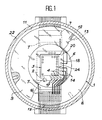
- the cold finger, the reading circuit and the photosensitive detection circuit are designated by the references 1, 2 and 3.
- Indium balls 4 connect by reading the reading circuit 2 and the detection circuit 3 ; some of these balls 4 serve as electrical connections between the two circuits.
- the end of the cold finger 1 is shaped so as to present a peripheral crown 5 surrounding a central hollow 6 and notched with radiating grooves 7, here two in number, between the central hollow 6 and the periphery of the cold finger 1.
- the crown 5 has a flat upper face 8 intended to serve as a support for a cover 9 in the form of a crown, traversed right through by a central window 10, cover 9, the flat lower face 11 of which rests on the upper surface 8 outside the grooves of the cold finger 1.
- Centering lugs 12 stand above the upper surface 8 and fit into corresponding housings 13 established on the cover 9, which can thus be assembled in a position well determined by relation to the cold finger 1.
- Part of the lower face 11 of the cover 9 carries electrical connection tracks 14 distributed in groups so as to come in front of the radiating grooves 7 when the cover 9 and the cold finger 1 are assembled.
- the cold finger 1 carries on its outer surface electrical lines 15 which are fixed to it and which lead to elastic electrical connectors 16 fixed to the bottom of the radiating grooves 7 of the cold finger 1.
- the free end of each connector 16 touches one of the electrical connection tracks 14 and is slightly deformed.
- the metallic connection tracks 14 deviate near the window 10 and lead to respective wetting surfaces 17 which, with other insulated wetting surfaces 18, surround the window 10 on the underside 11.
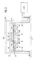
- wetting surfaces 17 and 18 are intended to allow the adhesion of additional indium balls 19 which also adhere to wetting surfaces of identical distribution established on the face 20 of the integrated circuit 2 which already carries the indium balls 4 for connection to the detection circuit 3.
- the reading circuit 2 is in fact contained in the central recess 6, while the detection circuit 3 is without direct contact with the cover 9 and is contained in the window 10.
- the central recess 6 and the window 10 together constitute a cavity which can be closed by placing a filter 21 - optional - on window 10.
- the information coming from the detection circuit 3 is therefore transmitted to the electrical lines 15 by the indium balls 4, the electrical connection tracks 24 installed on the reading circuit 2, the additional indium balls 19, the electrical connection tracks 14 and the connectors 16.
- the entire system is placed in a cryostat where it is protected from the outside environment by a screen 22 provided with a transparent window 23 opposite the detection circuit 3.
- the arrangement of the elements of the measurement system allows easy mounting and space saving since circuits 2 and 3 are housed inside a cavity. Alignment and parallelism of the two circuits 2 and 3 with the cold finger 1 are easily obtained using known techniques such as, for example, that described in international patent application 87 01 509.
- the indium balls 4 and 19 were previously soldered to the reading circuit 2 in a preliminary step of melting then cooling and resolidification. A new melting of the indium balls 4 and 19 causes them to spread over the wetting surfaces of the detection circuit 3 and of the cover 9.
- the weights of these two parts, as well as the surface tension forces prevailing in the molten balls, determine the distances from the detection circuit 3 and the cover 9 to the reading circuit 2. Excellent parallelism can be obtained with appropriate geometrical conditions, in particular if the weight distribution is uniform on the balls 4 and 19.
- the surface tension forces also ensure alignment of the wetting surfaces of the reading circuit 2 with those of the reading circuit 3 and of the cover 9 by horizontally moving these last two parts, as explained in the specification of the aforementioned application.
- the indium beads 4 and 19 are then left to cool until they re-solidify.
- the assembly is completed by coating the upper surface 8 with cold finger 1 and pressing the cover 9 on this upper surface 8 using a press. Excellent parallelism can be obtained between the cover 9 and the upper face 8 of the cold finger 1 since it is possible to press a flat end face of the press on the flat upper surface of the cover 9.
- Bonding can be replaced by welding; the press is then equipped with a winding heating the filler metal.
- the invention can also be implemented in many different ways, with supports such as the cold finger 1 and covers 9 of different shapes, as well as with metal studs of different chemical composition. It is possible to choose the metal of the balls 4 and 19 from indium and its alloys, the lead and tin alloys, the metal or the alloy of the balls 4 which may be different from that of the balls 19.
- the circuit of detection 3 can pick up infrared, ultraviolet, visible light or ionizing radiation in particular.
Landscapes
- Engineering & Computer Science (AREA)
- Physics & Mathematics (AREA)
- General Physics & Mathematics (AREA)
- Condensed Matter Physics & Semiconductors (AREA)
- Electromagnetism (AREA)
- Computer Hardware Design (AREA)
- Microelectronics & Electronic Packaging (AREA)
- Power Engineering (AREA)
- Mechanical Engineering (AREA)
- Thermal Sciences (AREA)
- General Engineering & Computer Science (AREA)
- Combustion & Propulsion (AREA)
- Spectroscopy & Molecular Physics (AREA)
- Chemical & Material Sciences (AREA)
- Photometry And Measurement Of Optical Pulse Characteristics (AREA)
Abstract
Système de mesure constitué d'un circuit de détection (3) d'un rayonnement soudé à un circuit de lecture (2) par des plots métalliques (4), lui-même soudé à un couvercle évidé (9) par d'autres plots métalliques (19). Le couvercle (9) est posé sur un doigt froid de cryostat (1) et une cavité (6 et 10) contient les deux circuits (2 et 3). Cette disposition évite de devoir coller et souder des fils de connexion électrique et simplifie donc l'assemblage ainsi que l'alignement et le parallélisme des différentes pièces.Measurement system consisting of a radiation detection circuit (3) welded to a reading circuit (2) by metal studs (4), itself welded to a hollow cover (9) by other studs metallic (19). The lid (9) is placed on a cold finger of the cryostat (1) and a cavity (6 and 10) contains the two circuits (2 and 3). This arrangement avoids having to glue and solder electrical connection wires and therefore simplifies assembly as well as the alignment and parallelism of the various parts.
Description
L'invention se rapporte à un système de mesure constitué en particulier d'un circuit de détection d'un rayonnement, d'un circuit de lecture et d'un support tel qu'un doigt froid de cryostat.The invention relates to a measurement system consisting in particular of a radiation detection circuit, a reading circuit and a support such as a cold cryostat finger.
La technique d'assemblage connue jusqu'à présent consiste à coller sur une face d'extrémité du doigt froid une plaque porteuse de pistes électriques de connexion, puis à coller sur la plaque le circuit de lecture après l'avoir soudé au circuit de détection au moyen de plots métalliques tels que des billes d'indium dont certains sont utilisés également pour assurer les connexions électriques entre les deux circuits.The assembly technique known up to now consists of gluing a plate carrying electrical connection tracks to an end face of the cold finger, then gluing the reading circuit to the plate after having soldered it to the detection circuit. by means of metal studs such as indium balls, some of which are also used to ensure the electrical connections between the two circuits.
On installe ensuite des fils conducteurs entre les pistes de la plaque et les emplacements de connexion du circuit de lecture d'une part, les lignes électriques fixées sur le doigt froid d'autre part. La transmission des informations originaires du circuit de détection vers des moyens d'enregistrement et d'exploitation est alors assurée.Then conducting wires are installed between the tracks of the plate and the connection locations of the reading circuit on the one hand, the electric lines fixed on the cold finger on the other hand. The transmission of information originating from the detection circuit to recording and operating means is then ensured.
Cette méthode est peu intéressante car les collages impliquent des difficultés d'alignement et de parallélisme corrects des circuits et l'installation des fils est une opération délicate et longue.This method is not very interesting because bonding involves difficulties of correct alignment and parallelism of the circuits and the installation of the wires is a delicate and long operation.
Ces étapes et donc les inconvénients qui leur sont liés sont éliminés en ayant recours à l'invention.These stages and therefore the drawbacks which are linked to them are eliminated by having recourse to the invention.
Le circuit de détection est encore soudé au circuit de lecture par des plots métalliques mais le système comprend en outre un couvercle fixé au support et délimitant une cavité avec lui, la cavité contenant les circuits, le couvercle étant muni de pistes conductrices électriques, le circuit de lecture étant soudé au couvercle par des plots métalliques dont certains au moins constituent des connexions électriques et touchent les pistes conductrices, le couvercle comprenant une fenêtre transparente en face de laquelle est disposé le circuit de détection.The detection circuit is still soldered to the reading circuit by metal studs, but the system also includes a cover fixed to the support and delimiting a cavity with it, the cavity containing the circuits, the cover being provided with electrical conductive tracks, the reading circuit being welded to the cover by metal studs, at least some of which constitute electrical connections and touch the conductive tracks, cover comprising a transparent window in front of which the detection circuit is arranged.
Le support présente avantageusement un creux central contenant le circuit de lecture et constituant au moins partiellement la cavité, ainsi qu'une couronne entourant le creux et entaillée de rainures rayonnantes en face des pistes de connexion électrique. Les rainures pourront alors contenir des connecteurs souples aux extrémités de lignes électriques, fixées au support et venant toucher des pistes de connexion électrique respectives.The support advantageously has a central recess containing the reading circuit and constituting at least partially the cavity, as well as a crown surrounding the recess and notched with radiating grooves opposite the electrical connection tracks. The grooves may then contain flexible connectors at the ends of electrical lines, fixed to the support and coming to touch the respective electrical connection tracks.
L'invention va maintenant être décrite plus en détail à l'aide des figures suivantes annexées à titre illustratif et nullement limitatif d'une réalisation de l'invention :
- - la figure 1 représente une vue de face du support et du couvercle dans leur plan d'assemblage ; et
- - la figure 2 représente une vue en coupe axiale de l'invention.
- - Figure 1 shows a front view of the support and the cover in their assembly plane; and
- - Figure 2 shows an axial sectional view of the invention.
Sur ces figures, le doigt froid, le circuit de lecture et le circuit photosensible de détection sont désignés par les références 1, 2 et 3. Des billes d'indium 4 relient en les soudant le circuit de lecture 2 et le circuit de détection 3 ; certaines de ces billes 4 servent de connexions électriques entre les deux circuits.In these figures, the cold finger, the reading circuit and the photosensitive detection circuit are designated by the
Dans la réalisation illustrée de l'invention, l'extrémité du doigt froid 1 est façonnée de manière à présenter une couronne périphérique 5 entourant un creux central 6 et entaillée de rainures rayonnantes 7, ici au nombre de deux, entre le creux central 6 et le pourtour du doigt froid 1.In the illustrated embodiment of the invention, the end of the
La couronne 5 présente une face supérieure plane 8 destinée à servir d'appui à un couvercle 9 en forme de couronne, traversé de part en part par une fenêtre centrale 10, couvercle 9 dont la face inférieure plane 11 s'appuie sur la surface supérieure 8 extérieure aux rainures du doigt froid 1. Des ergots de centrage 12 se dressent au-dessus de la surface supérieure 8 et s'emboîtent dans des logements correspondants 13 établis sur le couvercle 9, qui peut ainsi être assemblé dans une position bien déterminée par rapport au doigt froid 1.The
Une partie de la face inférieure 11 du couvercle 9 porte des pistes de connexion électrique 14 réparties en groupes de façon à venir en face des rainures rayonnantes 7 quand le couvercle 9 et le doigt froid 1 sont assemblés. Le doigt froid 1 porte sur sa surface extérieure des lignes électriques 15 qui lui sont fixées et qui aboutissent à des connecteurs électriques 16 élastiques fixés au fond des rainures rayonnantes 7 du doigt froid 1. Quand l'assemblage est réalisé, l'extrémité libre de chaque connecteur 16 vient toucher une des pistes de connexion électrique 14 et est légèrement déformée.Part of the
Les pistes métalliques de connexion 14 s'écartent à proximité de la fenêtre 10 et aboutissent à des surfaces mouillantes 17 respectives qui, avec d'autres surfaces mouillantes isolées 18, entourent la fenêtre 10 sur la face inférieure 11.The
Ces surfaces mouillantes 17 et 18 sont destinées à permettre l'adhérence de billes d'indium supplémentaires 19 qui adhèrent également à des surfaces mouillantes de répartition identique établies sur la face 20 du circuit intégré 2 qui porte déjà les billes d'indium 4 de liaison au circuit de détection 3. On obtient donc une disposition où le circuit de lecture 2 n'est maintenu en place que par les billes d'indium supplémentaires 19 et où son autre face n'a de contact direct avec aucune autre pièce, contrairement à la technique antérieure où cette face était collée. Le circuit de lecture 2 est en fait contenu dans le creux central 6, alors que le circuit de détection 3 est sans contact direct avec le couvercle 9 et est contenu dans la fenêtre 10. Le creux central 6 et la fenêtre 10 constituent ensemble une cavité qui peut être fermée en disposant un filtre 21 -facultatif- sur la fenêtre 10.These
Les informations provenant du circuit de détection 3 sont donc transmises aux lignes électriques 15 par les billes d'indium 4, des pistes de connexion électrique 24 installées sur le circuit de lecture 2, les billes d'indium supplémentaires 19, les pistes de connexion électrique 14 et les connecteurs 16.The information coming from the
L'ensemble du système est disposé dans un cryostat où il est protégé du milieu extérieur par un écran 22 muni d'une fenêtre transparente 23 en face du circuit de détection 3.The entire system is placed in a cryostat where it is protected from the outside environment by a
La disposition des éléments du système de mesure permet un montage facile et un gain d'espace puisque les circuits 2 et 3 sont logés à l'intérieur d'une cavité. Un alignement et un parallélisme des deux circuits 2 et 3 avec le doigt froid 1 sont facilement obtenus en utilisant des techniques connues telles que, par exemple, celle exposée dans la demande de brevet internationale 87 01 509. Dans le cas présent, on pose le circuit de lecture 2 sur une sole chauffante, le circuit de détection 3 sur le circuit de lecture 2 et le couvercle 9 sur le circuit de lecture 2. Les billes d'indium 4 et 19 ont été préalablement soudées au circuit de lecture 2 dans une étape préliminaire de fusion puis de refroidissement et de resolidification. Une nouvelle fusion des billes d'indium 4 et 19 les fait s'étaler sur les surfaces mouillantes du circuit de détection 3 et du couvercle 9. Les poids de ces deux pièces, ainsi que les forces de tension superficielle régnant dans les billes fondues, déterminent les distances du circuit de détection 3 et du couvercle 9 au circuit de lecture 2. Un parallélisme excellent peut être obtenu avec des conditions géométriques appropriées, notamment si la répartition des poids est uniforme sur les billes 4 et 19. Les forces de tension superficielle assurent également l'alignement des surfaces mouillantes du circuit de lecture 2 avec celles du circuit de lecture 3 et du couvercle 9 en déplaçant horizontalement ces deux dernières pièces, comme il est expliqué dans le fascicule de la demande précitée.The arrangement of the elements of the measurement system allows easy mounting and space saving since
Les billes d'indium 4 et 19 sont ensuite laissées refroidir jusqu'à ce qu'elles se resolidifient. L'assemblage est complété en enduisant de colle la surface supérieure 8 du doigt froid 1 et en appuyant le couvercle 9 sur cette surface supérieure 8 à l'aide d'une presse. Un excellent parallélisme peut être obtenu entre le couvercle 9 et la face supérieure 8 du doigt froid 1 car on peut appuyer une face d'extrémité plane de la presse sur la surface supérieure plane du couvercle 9.The
Le collage peut être remplacé par un soudage ; la presse est alors équipée d'un enroulement chauffant le métal d'apport.Bonding can be replaced by welding; the press is then equipped with a winding heating the filler metal.
L'invention peut encore être mise en oeuvre de bien des manières différentes, avec des supports tels que le doigt froid 1 et des couvercles 9 de formes différentes, de même qu'avec des plots métalliques de liaison de composition chimique différente. Il est possible de choisir le métal des billes 4 et 19 parmi l'indium et ses alliages, les alliages de plomb et d'étain, le métal ou l'alliage des billes 4 pouvant être différent de celui des billes 19. Le circuit de détection 3 peut capter selon le cas de l'infrarouge, de l'ultraviolet, de la lumière visible ou des rayonnements ionisants en particulier.The invention can also be implemented in many different ways, with supports such as the
Claims (4)
Applications Claiming Priority (2)
| Application Number | Priority Date | Filing Date | Title |
|---|---|---|---|
| FR8905711A FR2646559B1 (en) | 1989-04-28 | 1989-04-28 | MEASURING SYSTEM CONSISTING OF A RADIATION DETECTION CIRCUIT, A READING CIRCUIT AND A MEDIUM SUCH AS A COLD CRYOSTAT FINGER |
| FR8905711 | 1989-04-28 |
Publications (2)
| Publication Number | Publication Date |
|---|---|
| EP0395487A1 true EP0395487A1 (en) | 1990-10-31 |
| EP0395487B1 EP0395487B1 (en) | 1994-07-13 |
Family
ID=9381272
Family Applications (1)
| Application Number | Title | Priority Date | Filing Date |
|---|---|---|---|
| EP90401096A Expired - Lifetime EP0395487B1 (en) | 1989-04-28 | 1990-04-24 | Measuring system consisting of a radiation detection circuit and a support such as a cold finger of a cryostat |
Country Status (4)
| Country | Link |
|---|---|
| US (1) | US4983840A (en) |
| EP (1) | EP0395487B1 (en) |
| DE (1) | DE69010560T2 (en) |
| FR (1) | FR2646559B1 (en) |
Cited By (3)
| Publication number | Priority date | Publication date | Assignee | Title |
|---|---|---|---|---|
| EP0485312A1 (en) * | 1990-11-09 | 1992-05-13 | Societe Francaise De Detecteurs, Infrarouges- Sofradir | Process for fabricating the reversible assembling of an electronic circuit for reading and/or exploitation and of an electricity conductive or non-conductive holder |
| EP0723142A1 (en) * | 1995-01-20 | 1996-07-24 | Societe Francaise De Detecteurs, Infrarouges- Sofradir | Device for detection of electromagnetic waves, and especially of infrared radiation |
| WO2013182763A1 (en) * | 2012-06-08 | 2013-12-12 | Société Française De Détecteurs Infrarouges - Sofradir | Cooled detection device with improved cold plate |
Families Citing this family (5)
| Publication number | Priority date | Publication date | Assignee | Title |
|---|---|---|---|---|
| FR2651315B1 (en) * | 1989-08-22 | 1991-11-15 | Detecteurs Infra Rouges Ste Fs | INFRARED DETECTION DEVICE. |
| GB2326029A (en) * | 1997-06-03 | 1998-12-09 | Marconi Gec Ltd | Cryogenic electronic assembly with stripline connection and adjustment means |
| US5929448A (en) * | 1997-09-03 | 1999-07-27 | The United States Of America As Represented By The Secretary Of The Air Force | Redundant transistor dose monitor circuit using two ICs |
| DE69922177T2 (en) * | 1999-01-19 | 2005-12-01 | Koninklijke Philips Electronics N.V. | X-ray detector |
| CN105702696B (en) * | 2016-04-12 | 2019-10-25 | 华天科技(昆山)电子有限公司 | The encapsulating structure and preparation method thereof of image sensing chip |
Citations (4)
| Publication number | Priority date | Publication date | Assignee | Title |
|---|---|---|---|---|
| EP0058645A1 (en) * | 1981-02-09 | 1982-08-25 | SELENIA INDUSTRIE ELETTRONICHE ASSOCIATE S.p.A. | Infrared radiation detector device |
| EP0136687A2 (en) * | 1983-10-03 | 1985-04-10 | Honeywell Inc. | Infrared receiver |
| EP0213421A2 (en) * | 1985-08-07 | 1987-03-11 | Honeywell Inc. | Infrared detector assembly having vacuum chambers |
| WO1987001448A1 (en) * | 1985-09-03 | 1987-03-12 | Santa Barbara Research Center | Integrated infrared detector and cryoengine assembly |
Family Cites Families (9)
| Publication number | Priority date | Publication date | Assignee | Title |
|---|---|---|---|---|
| US3405273A (en) * | 1966-05-02 | 1968-10-08 | Santa Barbara Res Ct | Detector arrangement having a collector with electrically insulating porous material thereon |
| DE2540186C2 (en) * | 1975-09-10 | 1985-03-28 | ANT Nachrichtentechnik GmbH, 7150 Backnang | Arrangement for contacting the ground plane of a carrier plate for electronic circuits |
| JPS59107086A (en) * | 1982-12-08 | 1984-06-21 | Hitachi Zosen Corp | Manufacture of halogen enabling use of accumulated electric power |
| FR2544132B1 (en) * | 1983-04-08 | 1986-11-21 | Telecommunications Sa | OPTICAL IMMERSION PHOTOCONDUCTIVE DETECTOR |
| JPS60155928A (en) * | 1984-01-25 | 1985-08-16 | Fujitsu Ltd | Infrared ray detector |
| JPS61157290U (en) * | 1985-03-22 | 1986-09-29 | ||
| US4766316A (en) * | 1985-08-07 | 1988-08-23 | Honeywell Inc. | Disc detector assembly having vacuum chamber |
| GB8522429D0 (en) * | 1985-09-10 | 1985-10-16 | Plessey Co Plc | Alignment for hybrid device |
| US4728751A (en) * | 1986-10-06 | 1988-03-01 | International Business Machines Corporation | Flexible electrical connection and method of making same |
-
1989
- 1989-04-28 FR FR8905711A patent/FR2646559B1/en not_active Expired - Lifetime
-
1990
- 1990-04-19 US US07/513,101 patent/US4983840A/en not_active Expired - Fee Related
- 1990-04-24 DE DE69010560T patent/DE69010560T2/en not_active Expired - Fee Related
- 1990-04-24 EP EP90401096A patent/EP0395487B1/en not_active Expired - Lifetime
Patent Citations (4)
| Publication number | Priority date | Publication date | Assignee | Title |
|---|---|---|---|---|
| EP0058645A1 (en) * | 1981-02-09 | 1982-08-25 | SELENIA INDUSTRIE ELETTRONICHE ASSOCIATE S.p.A. | Infrared radiation detector device |
| EP0136687A2 (en) * | 1983-10-03 | 1985-04-10 | Honeywell Inc. | Infrared receiver |
| EP0213421A2 (en) * | 1985-08-07 | 1987-03-11 | Honeywell Inc. | Infrared detector assembly having vacuum chambers |
| WO1987001448A1 (en) * | 1985-09-03 | 1987-03-12 | Santa Barbara Research Center | Integrated infrared detector and cryoengine assembly |
Cited By (7)
| Publication number | Priority date | Publication date | Assignee | Title |
|---|---|---|---|---|
| EP0485312A1 (en) * | 1990-11-09 | 1992-05-13 | Societe Francaise De Detecteurs, Infrarouges- Sofradir | Process for fabricating the reversible assembling of an electronic circuit for reading and/or exploitation and of an electricity conductive or non-conductive holder |
| FR2669177A1 (en) * | 1990-11-09 | 1992-05-15 | Sofradir Ste Fse Detecteurs In | METHOD FOR REALIZING THE REVERSIBLE ASSEMBLY OF AN ELECTRONIC READING AND / OR OPERATING CIRCUIT AND A CONDUCTIVE OR NON-ELECTRICAL SUPPORT. |
| US5182852A (en) * | 1990-11-09 | 1993-02-02 | Societe Francaise De Detecteurs Infrarouges (Sofradir) | Reversible production process for assembly of circuit board and substrate |
| EP0723142A1 (en) * | 1995-01-20 | 1996-07-24 | Societe Francaise De Detecteurs, Infrarouges- Sofradir | Device for detection of electromagnetic waves, and especially of infrared radiation |
| FR2729757A1 (en) * | 1995-01-20 | 1996-07-26 | Sofradir | DEVICE FOR DETECTING ELECTROMAGNETIC WAVES, IN PARTICULAR IN INFRA RED RADIATION |
| US5619039A (en) * | 1995-01-20 | 1997-04-08 | Societe Francaise De Detecteurs Infra-Rouges - Sofradir | Device for the detection of electromagnetic waves and, in particular, of infrared radiation |
| WO2013182763A1 (en) * | 2012-06-08 | 2013-12-12 | Société Française De Détecteurs Infrarouges - Sofradir | Cooled detection device with improved cold plate |
Also Published As
| Publication number | Publication date |
|---|---|
| DE69010560D1 (en) | 1994-08-18 |
| US4983840A (en) | 1991-01-08 |
| FR2646559B1 (en) | 1991-07-05 |
| FR2646559A1 (en) | 1990-11-02 |
| EP0395487B1 (en) | 1994-07-13 |
| DE69010560T2 (en) | 1995-02-09 |
Similar Documents
| Publication | Publication Date | Title |
|---|---|---|
| EP0395487B1 (en) | Measuring system consisting of a radiation detection circuit and a support such as a cold finger of a cryostat | |
| EP1388174B1 (en) | Shielded housing for optical semiconductor component | |
| FR2700416A1 (en) | Semiconductor device having a semiconductor element on a mounting element. | |
| FR2465335A1 (en) | SEMICONDUCTOR LASER DEVICE | |
| FR2786320A1 (en) | Non-aqueous electrolyte battery has metal rings hermetically sealed around terminals by insulating glass or ceramic sealing material | |
| CA2056193C (en) | Connection piece for electrified glazing | |
| EP0229549B1 (en) | Hermetic coaxial connector | |
| EP0599174A1 (en) | Micro-machined sensor | |
| EP0209717A1 (en) | Battery compartment for an electronic watch | |
| EP0717442A1 (en) | Process and integrated circuit connection support to another support by means of bumps | |
| EP0524038A1 (en) | Method of wiring the external leads of a housing and the hybrid elements | |
| EP0779775B1 (en) | Electronic assembly with heat transfer, particularly for high voltage transformer of a discharge head lamp of a vehicle | |
| EP0114760B1 (en) | Highly thermal dissipation housing, especially for microelectronics | |
| EP0111449B1 (en) | Method to manufacture an exterior part of a time piece, and part obtained by the same | |
| EP0094869B1 (en) | Encapsulating housing for a microelectronic circuit with high heat dissipation, and its manufacturing method | |
| FR3058261A1 (en) | METHOD FOR MAKING AN ELECTRICAL CONNECTION BETWEEN AN ELECTRONIC CHIP AND A SUPPORT PLATE AND ELECTRONIC DEVICE | |
| EP1278240A2 (en) | Transfering method of a component onto a connection support by welding without supplying material | |
| WO2007096515A1 (en) | Method for assembling a package comprising metallic parts and resulting package | |
| EP0983712B1 (en) | Electronic plate folded at 45 degrees | |
| EP0901167A1 (en) | Base for power diode of vehicle alternator | |
| EP0129274A1 (en) | Water-tight watch case | |
| CA2054912A1 (en) | Method for protecting the electronic components of a circuit against radiations and device using said method | |
| FR3058260A1 (en) | METHOD FOR MAKING AN ELECTRICAL CONNECTION BETWEEN AN ELECTRONIC CHIP AND A SUPPORT PLATE AND ELECTRONIC DEVICE | |
| EP1617015A2 (en) | Metal mast and its construction method | |
| JPH0246056Y2 (en) |
Legal Events
| Date | Code | Title | Description |
|---|---|---|---|
| PUAI | Public reference made under article 153(3) epc to a published international application that has entered the european phase |
Free format text: ORIGINAL CODE: 0009012 |
|
| AK | Designated contracting states |
Kind code of ref document: A1 Designated state(s): DE GB IT |
|
| 17P | Request for examination filed |
Effective date: 19910404 |
|
| 17Q | First examination report despatched |
Effective date: 19930809 |
|
| GRAA | (expected) grant |
Free format text: ORIGINAL CODE: 0009210 |
|
| AK | Designated contracting states |
Kind code of ref document: B1 Designated state(s): DE GB IT |
|
| REF | Corresponds to: |
Ref document number: 69010560 Country of ref document: DE Date of ref document: 19940818 |
|
| ITF | It: translation for a ep patent filed |
Owner name: JACOBACCI CASETTA & PERANI S.P.A. |
|
| GBT | Gb: translation of ep patent filed (gb section 77(6)(a)/1977) |
Effective date: 19940919 |
|
| PLBE | No opposition filed within time limit |
Free format text: ORIGINAL CODE: 0009261 |
|
| STAA | Information on the status of an ep patent application or granted ep patent |
Free format text: STATUS: NO OPPOSITION FILED WITHIN TIME LIMIT |
|
| 26N | No opposition filed | ||
| PGFP | Annual fee paid to national office [announced via postgrant information from national office to epo] |
Ref country code: GB Payment date: 19990415 Year of fee payment: 10 |
|
| PGFP | Annual fee paid to national office [announced via postgrant information from national office to epo] |
Ref country code: DE Payment date: 19990503 Year of fee payment: 10 |
|
| PG25 | Lapsed in a contracting state [announced via postgrant information from national office to epo] |
Ref country code: GB Free format text: LAPSE BECAUSE OF NON-PAYMENT OF DUE FEES Effective date: 20000424 |
|
| GBPC | Gb: european patent ceased through non-payment of renewal fee |
Effective date: 20000424 |
|
| PG25 | Lapsed in a contracting state [announced via postgrant information from national office to epo] |
Ref country code: DE Free format text: LAPSE BECAUSE OF NON-PAYMENT OF DUE FEES Effective date: 20010201 |
|
| PG25 | Lapsed in a contracting state [announced via postgrant information from national office to epo] |
Ref country code: IT Free format text: LAPSE BECAUSE OF NON-PAYMENT OF DUE FEES;WARNING: LAPSES OF ITALIAN PATENTS WITH EFFECTIVE DATE BEFORE 2007 MAY HAVE OCCURRED AT ANY TIME BEFORE 2007. THE CORRECT EFFECTIVE DATE MAY BE DIFFERENT FROM THE ONE RECORDED. Effective date: 20050424 |