EP0058098A1 - Fernsehgerät mit Schirm-Zentriermitteln in seiner Vorderöffnung - Google Patents
Fernsehgerät mit Schirm-Zentriermitteln in seiner Vorderöffnung Download PDFInfo
- Publication number
- EP0058098A1 EP0058098A1 EP82400048A EP82400048A EP0058098A1 EP 0058098 A1 EP0058098 A1 EP 0058098A1 EP 82400048 A EP82400048 A EP 82400048A EP 82400048 A EP82400048 A EP 82400048A EP 0058098 A1 EP0058098 A1 EP 0058098A1
- Authority
- EP
- European Patent Office
- Prior art keywords
- television receiver
- belt
- receiver according
- screen
- housing
- Prior art date
- Legal status (The legal status is an assumption and is not a legal conclusion. Google has not performed a legal analysis and makes no representation as to the accuracy of the status listed.)
- Granted
Links
- 210000002105 tongue Anatomy 0.000 claims description 22
- 238000012423 maintenance Methods 0.000 claims description 2
- 230000000295 complement effect Effects 0.000 description 3
- 210000005069 ears Anatomy 0.000 description 3
- 238000010586 diagram Methods 0.000 description 2
- 230000002093 peripheral effect Effects 0.000 description 2
- 238000010079 rubber tapping Methods 0.000 description 2
- 241000269908 Platichthys flesus Species 0.000 description 1
- 239000006185 dispersion Substances 0.000 description 1
- 238000006073 displacement reaction Methods 0.000 description 1
- 230000001788 irregular Effects 0.000 description 1
- 229910052751 metal Inorganic materials 0.000 description 1
- 230000004048 modification Effects 0.000 description 1
- 238000012986 modification Methods 0.000 description 1
- 210000000056 organ Anatomy 0.000 description 1
- 230000000149 penetrating effect Effects 0.000 description 1
- 230000000717 retained effect Effects 0.000 description 1
- 238000000926 separation method Methods 0.000 description 1
Images

Classifications
-
- H—ELECTRICITY
- H04—ELECTRIC COMMUNICATION TECHNIQUE
- H04N—PICTORIAL COMMUNICATION, e.g. TELEVISION
- H04N5/00—Details of television systems
- H04N5/64—Constructional details of receivers, e.g. cabinets or dust covers
- H04N5/645—Mounting of picture tube on chassis or in housing
Definitions
- the invention relates to a television receiver.
- the screen of a television set consists of the front face of a cathode ray tube, most of which is enclosed in a box, the front of which has a large opening allowing visibility of the screen.
- a television being, of course, most of the time observed by its facade it is easily understood that the aesthetics of it must be well taken care of.
- the screen must be centered relative to the opening on the front. This condition is particularly critical when, as is the case in most televisions, the screen protrudes outside the housing, the edge of the opening of the front of this housing thus surrounding with a certain play - necessary by the dispersions of the dimensions of the tubes and boxes manufactured in series - the rim of the tube at the back of the screen. Indeed if the game is not evenly distributed the television is unsightly.
- the positioning of the cathode ray tube with respect to the front of the television set is an operation which requires significant labor time.
- the assembly is carried out as follows: the front of the box previously arranged horizontally (front face down) receives, by manual or automatic operation, the slab of the tube (front part) of the television also presented horizontally down ; under these conditions the clearance between the opening of the front of the housing and the peripheral edge of the screen is practically not visible to the operator; in order for this play to be visible, it is then necessary to modify the position of the front assembly of the cathode-ray tube box and, if the centering is not correct, start again the assembly which is thus carried out by trial and error.
- the invention overcomes this drawback.
- the television receiver according to the invention is characterized in that it comprises elastic members acting on the belt of the cathode ray tube to arrange the screen in the opening of the front of the housing of the television in such a way that the play between the edge of the opening and the rim of the tube at the back of the screen is regular and means for fixing the belt to the case.
- the automatic centering means can thus be particularly simple.
- the elastic members are integral with the housing.
- these elastic members act in the vicinity of the four corners - generally rounded - of the generally rectangular belt.
- Each elastic member comprises for example a tongue with which is associated a similar tongue so that, when the television is mounted, these two tongues exert forces, the result of which is on a line at 45 ° with the median axes of the sides of the belt and goes through the corner of this belt on either side of which are arranged the two tabs.
- each elastic member is secured to a plate which, after assembly, is in contact with a high coefficient of friction with a corresponding ear fixed to the belt of the tube.
- the tube remains well positioned relative to the opening of the facade, the high friction preventing relative displacement of the tube and the facade.
- the front 1 of the housing 2 of the television is an element which does not form a single piece with the rest of the housing.
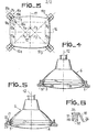
- This facade 1 has a window 3 through which the curved face 4 (FIG. 5) exits forming the screen of the screen 5 of the cathode ray tube 6 of the television set.
- means are provided making it possible, during assembly, to automatically center the slab 5 relative to the window 3, that is to say to obtain a regular clearance 7 between the periphery of the screen and the edges of window 3. These means also make it possible to maintain centering after mounting.
- the belt 11 is a metallic element surrounding the tube at the rear of the slab and whose section through a plane passing through the axis 12 is formed of rectilinear segments parallel to this axis.
- the belt 11 In section through a plane perpendicular to the axis 12, the belt 11 has the general shape of a rectangle with slightly curved sides and vertices 13 1 to 13 4 (FIG. 3) rounded. This belt is centered relative to the slab.
- the belt 11 protrudes, in a manner known per se, at its four corners, ears 14 (FIG. 2) for fixing the belt, and therefore the tube, to the facade 1.
- each corner of the belt is associated with a couple 10 1 , 10 2 , 10 3 , 10 4 (FIG. 3) of elastic tabs which, when the television is mounted, apply forces the result of which is according to a line 15 passing through the corresponding vertex 13 of the belt and forming an angle of 45 ° with each of the median axes, respectively 16 and 17, of the sides of this belt.
- Each of these pairs comprises a first tongue 18 near the top 13 and a second tongue 19 in a position symmetrical to that of the tongue 18 relative to the line 15 passing through the corresponding top 13.
- the two tongues 18 and 19 of the same pair are attached elastically to the same plate 20 fixed to the internal part of the facade 1 and arranged in a plane perpendicular to the axis 12.
- the plate 20 and the projection 50 have an opening 51 for the passage of a screw 21 with an axis parallel to the axis 12 and passing through, after assembly, the ear 14 through the opening presented by the latter.
- the hole 51 ends, opposite the plate 20, by a countersink 52 constituting a housing for receiving the hexagon head of the screw 21.
- the part of the plate 20 around the projection 50 is in abutment against the end edge of the tubular element 22 and against the free edges of ribs 23 a (FIG. 2) connecting this element 22 to a flange 24 of the facade .
- the irregularities at the periphery of the projection 50 and the complementary hollow irregularities in the opening of the projection 22 on the facade prevent the rotation of the plate 20 and therefore the rotation of the tongues 18 and 19.
- the shape complementary to the hexagon of the screw heads 21 and of the countersink 52 prevents rotation of the screw relative to the plate 20.
- the screw 21 cooperates with a tapping of the tube 22; this tapping can be carried out by the screw itself.
- the tongues 18 and 19 form an obtuse angle with the plate 20 and have a direction such that they converge towards the front of the receiver away from the plate 20. They are separated from each other by a slot 25. The angle formed between them by the planes of these two tongues 18 and 19 is also obtuse.
- Each of the tongues ends with a bevel 26.
- the tube is released when it is very close to or comes into contact with the tabs. This tube is no longer retained, either by hand or by an automatic device which could exert on it horizontal forces unfavorable for centering, it acquires the desired position thanks to its own weight and the elastic forces exerted by the tabs.
- the tube is fixed to the front of the housing by nuts (not shown) cooperating with the screws 21 so as to tighten the ears 14 against the plates 20.
- the faces intended to be in contact with one another each plate 20 and the corresponding ear have surface states such that the coefficient of friction between these surfaces is high so as to contribute to the maintenance of the tube with respect to the front 1 of the housing of the television set.
- the tongues and the plate to which they are attached elastically are for example made of plastic.
- the invention applies to any type of television, without significant modification of the latter.
Landscapes
- Engineering & Computer Science (AREA)
- Multimedia (AREA)
- Signal Processing (AREA)
- Devices For Indicating Variable Information By Combining Individual Elements (AREA)
Applications Claiming Priority (2)
| Application Number | Priority Date | Filing Date | Title |
|---|---|---|---|
| FR8100474 | 1981-01-13 | ||
| FR8100474A FR2498036A1 (fr) | 1981-01-13 | 1981-01-13 | Recepteur de television a moyens de centrage de l'ecran dans l'ouverture de sa facade |
Publications (2)
| Publication Number | Publication Date |
|---|---|
| EP0058098A1 true EP0058098A1 (de) | 1982-08-18 |
| EP0058098B1 EP0058098B1 (de) | 1984-07-18 |
Family
ID=9254074
Family Applications (1)
| Application Number | Title | Priority Date | Filing Date |
|---|---|---|---|
| EP19820400048 Expired EP0058098B1 (de) | 1981-01-13 | 1982-01-12 | Fernsehgerät mit Schirm-Zentriermitteln in seiner Vorderöffnung |
Country Status (3)
| Country | Link |
|---|---|
| EP (1) | EP0058098B1 (de) |
| DE (1) | DE3260378D1 (de) |
| FR (1) | FR2498036A1 (de) |
Cited By (1)
| Publication number | Priority date | Publication date | Assignee | Title |
|---|---|---|---|---|
| EP0232917A2 (de) * | 1986-02-14 | 1987-08-19 | Siemens Nixdorf Informationssysteme Aktiengesellschaft | Verfahren sowie Klemmverbindung und Halterung zur Montage von Bildschirmgeräten |
Families Citing this family (1)
| Publication number | Priority date | Publication date | Assignee | Title |
|---|---|---|---|---|
| DE3619232A1 (de) * | 1986-06-07 | 1987-12-10 | Electronic Werke Deutschland | Fernsehempfaenger mit einer bildroehre und einem deckrahmen |
Citations (3)
| Publication number | Priority date | Publication date | Assignee | Title |
|---|---|---|---|---|
| US2165779A (en) * | 1937-06-30 | 1939-07-11 | Rca Corp | Cathode ray tube support |
| DE1154880B (de) * | 1960-07-01 | 1963-09-26 | Telefunken Patent | Vorrichtung zur Halterung und Zentrierung einer Kathodenstrahlroehre |
| FR1433771A (fr) * | 1964-04-29 | 1966-04-01 | Thomson Houston Comp Francaise | Dispositif de montage d'un tube cathodique |
-
1981
- 1981-01-13 FR FR8100474A patent/FR2498036A1/fr active Granted
-
1982
- 1982-01-12 DE DE8282400048T patent/DE3260378D1/de not_active Expired
- 1982-01-12 EP EP19820400048 patent/EP0058098B1/de not_active Expired
Patent Citations (3)
| Publication number | Priority date | Publication date | Assignee | Title |
|---|---|---|---|---|
| US2165779A (en) * | 1937-06-30 | 1939-07-11 | Rca Corp | Cathode ray tube support |
| DE1154880B (de) * | 1960-07-01 | 1963-09-26 | Telefunken Patent | Vorrichtung zur Halterung und Zentrierung einer Kathodenstrahlroehre |
| FR1433771A (fr) * | 1964-04-29 | 1966-04-01 | Thomson Houston Comp Francaise | Dispositif de montage d'un tube cathodique |
Cited By (2)
| Publication number | Priority date | Publication date | Assignee | Title |
|---|---|---|---|---|
| EP0232917A2 (de) * | 1986-02-14 | 1987-08-19 | Siemens Nixdorf Informationssysteme Aktiengesellschaft | Verfahren sowie Klemmverbindung und Halterung zur Montage von Bildschirmgeräten |
| EP0232917A3 (en) * | 1986-02-14 | 1989-09-20 | Siemens Aktiengesellschaft | Method as well as clamp and support for the mounting of visual display devices |
Also Published As
| Publication number | Publication date |
|---|---|
| EP0058098B1 (de) | 1984-07-18 |
| FR2498036B1 (de) | 1985-04-05 |
| FR2498036A1 (fr) | 1982-07-16 |
| DE3260378D1 (en) | 1984-08-23 |
Similar Documents
| Publication | Publication Date | Title |
|---|---|---|
| FR2691415A1 (fr) | Dispositif de montage du genre rotule et élément intermédiaire, notamment pour réflecteur de projecteur de véhicule automobile. | |
| EP1720395B1 (de) | Belüftungsvorrichtung mit Befestigungseinrichtung mit Federstreifen | |
| EP0058098B1 (de) | Fernsehgerät mit Schirm-Zentriermitteln in seiner Vorderöffnung | |
| EP0605266B1 (de) | Geräteträger anzubringen auf einen Kabelkanal mit einander gegenüberliegenden Vorsprüngen | |
| FR2647863A1 (fr) | Ensemble d'ecrou a verrouillage | |
| EP0195721A1 (de) | Vorrichtung zum Verhindern des Aushängens von Schiebetüren | |
| FR2554299A1 (fr) | Console de visualisation | |
| EP0499506B1 (de) | Käfigmutter zur Blindbefestigung auf Platten mit variabler Dicke | |
| EP0461974A1 (de) | Schiene für Kabelrinne | |
| EP0468869A1 (de) | Platte für elektrisches Gerät und dazu gehörende Haltevorrichtung | |
| EP0394413B1 (de) | Fernsehgerätvorderöffnung | |
| FR2552366A1 (fr) | Dispositif de fixation d'une partie de moule sur un support, en particulier dans une machine de moulage | |
| FR2632459A1 (fr) | Embase de connexion, en particulier de connexion pour prise coaxiale, a montage en facade | |
| EP0560034A1 (de) | Montagevorrichtung für Zubehörseite auf Skis | |
| EP0575224B1 (de) | Verkehrszeichen | |
| EP1478067B1 (de) | Bündig montiertes, interaktives Anzeigesystem | |
| EP3807546B1 (de) | Befestigungsvorrichtung mit einer plattenkante angepasst zur aufnahme einer mutterklemme und eine mutterklemme | |
| EP1069813B1 (de) | Frontplatte für eine elektronische Baugruppe, elektronische Baugruppe, und deren Einschub- oder Ausziehverfahren aus einem Baugruppenträger | |
| FR2719392A1 (fr) | Monture de diapositive. | |
| FR2593864A1 (fr) | Dispositif de calage automatique d'un organe sur un arbre, notamment d'une helice de ventilation sur un arbre d'entrainement | |
| FR2811929A1 (fr) | Dispositif de decoupage d'un materiau tel qu'une feuille de materiau souple ou semi rigide | |
| EP0196261A2 (de) | Einsatz für eine Brillenfassung | |
| FR2816715A1 (fr) | Dispositif d'aide a la lecture pour personnes malvoyantes | |
| FR2514400A1 (fr) | Dispositif de survitrage pour vantail de fenetre ou porte | |
| FR2771592A1 (fr) | Coffret equipe d'un rail de support pour de quelconques appareils, notamment pour de quelconques appareils electriques modulaires |
Legal Events
| Date | Code | Title | Description |
|---|---|---|---|
| PUAI | Public reference made under article 153(3) epc to a published international application that has entered the european phase |
Free format text: ORIGINAL CODE: 0009012 |
|
| AK | Designated contracting states |
Designated state(s): DE GB IT NL |
|
| 17P | Request for examination filed |
Effective date: 19820901 |
|
| ITF | It: translation for a ep patent filed | ||
| RAP1 | Party data changed (applicant data changed or rights of an application transferred) |
Owner name: SOCIETE ELECTRO MECANIQUE DU NIVERNAIS SELNI |
|
| GRAA | (expected) grant |
Free format text: ORIGINAL CODE: 0009210 |
|
| RAP1 | Party data changed (applicant data changed or rights of an application transferred) |
Owner name: SOCIETE D'ELECTRONIQUE DE LA REGION PAYS DE LOIRE |
|
| AK | Designated contracting states |
Designated state(s): DE GB IT NL |
|
| REF | Corresponds to: |
Ref document number: 3260378 Country of ref document: DE Date of ref document: 19840823 |
|
| PLBE | No opposition filed within time limit |
Free format text: ORIGINAL CODE: 0009261 |
|
| STAA | Information on the status of an ep patent application or granted ep patent |
Free format text: STATUS: NO OPPOSITION FILED WITHIN TIME LIMIT |
|
| 26N | No opposition filed | ||
| ITTA | It: last paid annual fee | ||
| REG | Reference to a national code |
Ref country code: GB Ref legal event code: 746 Effective date: 19971104 |
|
| PGFP | Annual fee paid to national office [announced via postgrant information from national office to epo] |
Ref country code: DE Payment date: 19990122 Year of fee payment: 18 |
|
| PGFP | Annual fee paid to national office [announced via postgrant information from national office to epo] |
Ref country code: NL Payment date: 19990128 Year of fee payment: 18 |
|
| PGFP | Annual fee paid to national office [announced via postgrant information from national office to epo] |
Ref country code: GB Payment date: 19991129 Year of fee payment: 19 |
|
| PG25 | Lapsed in a contracting state [announced via postgrant information from national office to epo] |
Ref country code: NL Free format text: LAPSE BECAUSE OF NON-PAYMENT OF DUE FEES Effective date: 20000801 |
|
| NLV4 | Nl: lapsed or anulled due to non-payment of the annual fee |
Effective date: 20000801 |
|
| PG25 | Lapsed in a contracting state [announced via postgrant information from national office to epo] |
Ref country code: DE Free format text: LAPSE BECAUSE OF NON-PAYMENT OF DUE FEES Effective date: 20001101 |
|
| PG25 | Lapsed in a contracting state [announced via postgrant information from national office to epo] |
Ref country code: GB Free format text: LAPSE BECAUSE OF NON-PAYMENT OF DUE FEES Effective date: 20010112 |
|
| GBPC | Gb: european patent ceased through non-payment of renewal fee |
Effective date: 20010112 |