EP0057120A2 - Method of heating a room by means of a compression heat pump using a mixed working medium - Google Patents
Method of heating a room by means of a compression heat pump using a mixed working medium Download PDFInfo
- Publication number
- EP0057120A2 EP0057120A2 EP82400042A EP82400042A EP0057120A2 EP 0057120 A2 EP0057120 A2 EP 0057120A2 EP 82400042 A EP82400042 A EP 82400042A EP 82400042 A EP82400042 A EP 82400042A EP 0057120 A2 EP0057120 A2 EP 0057120A2
- Authority
- EP
- European Patent Office
- Prior art keywords
- fluid
- mixed
- vaporized
- fraction
- heat exchange
- Prior art date
- Legal status (The legal status is an assumption and is not a legal conclusion. Google has not performed a legal analysis and makes no representation as to the accuracy of the status listed.)
- Granted
Links
Images

Classifications
-
- F—MECHANICAL ENGINEERING; LIGHTING; HEATING; WEAPONS; BLASTING
- F25—REFRIGERATION OR COOLING; COMBINED HEATING AND REFRIGERATION SYSTEMS; HEAT PUMP SYSTEMS; MANUFACTURE OR STORAGE OF ICE; LIQUEFACTION SOLIDIFICATION OF GASES
- F25B—REFRIGERATION MACHINES, PLANTS OR SYSTEMS; COMBINED HEATING AND REFRIGERATION SYSTEMS; HEAT PUMP SYSTEMS
- F25B9/00—Compression machines, plants or systems, in which the refrigerant is air or other gas of low boiling point
- F25B9/002—Compression machines, plants or systems, in which the refrigerant is air or other gas of low boiling point characterised by the refrigerant
- F25B9/006—Compression machines, plants or systems, in which the refrigerant is air or other gas of low boiling point characterised by the refrigerant the refrigerant containing more than one component
Landscapes
- Engineering & Computer Science (AREA)
- Physics & Mathematics (AREA)
- Mechanical Engineering (AREA)
- Thermal Sciences (AREA)
- General Engineering & Computer Science (AREA)
- Sorption Type Refrigeration Machines (AREA)
- Engine Equipment That Uses Special Cycles (AREA)
- Compression-Type Refrigeration Machines With Reversible Cycles (AREA)
- Beverage Vending Machines With Cups, And Gas Or Electricity Vending Machines (AREA)
Abstract
Description
La présente invention concerne un procédé de chauffage et de conditionnement thermique au moyen d'une pompe à chaleur à compression, fonctionnant avec un fluide mixte de travail.The present invention relates to a heating and thermal conditioning process by means of a compression heat pump, operating with a mixed working fluid.
L'utilisation dans une pompe à chaleur à compression d'un fluide mixte de travail, non azéotropique, qui se vaporise ou se-condense à une pression donnée dans un intervalle de température, et non à une température fixe, permet d'améliorer le coefficient de performance de ladite pompe à chaleur.The use in a compression heat pump of a mixed non-azeotropic working fluid which vaporizes or condenses at a given pressure in a temperature range, and not at a fixed temperature, makes it possible to improve the coefficient of performance of said heat pump.
Par fluide mixte de travail, non azéotropique, on entend un mélange d'au moins deux individus capables de se vaporiser et de se recondenser dans le domaine de travail de la pompe sans former d'azéotrope entre eux, en particulier deux individus chimiquement distincts (A) et (B) ne formant pas d'azéotrope entre eux dans le domaine de travail de la pompe ou un individu chimique (A) et un azéotrope (C) formé entre deux ou plusieurs autres individus chimiques, azéotropiquement indépendant de l'individu chimique (A), ou même deux azéotropes indépendants l'un de l'autre (C') et (C").The term “non-azeotropic mixed working fluid” means a mixture of at least two individuals capable of vaporizing and of being condensed in the working domain of the pump without forming an azeotrope between them, in particular two chemically distinct individuals ( A) and (B) not forming an azeotrope between them in the working area of the pump or a chemical individual (A) and an azeotrope (C) formed between two or more other chemical individuals, azeotropically independent of the individual chemical (A), or even two azeotropes independent of each other (C ') and (C ").
Dans un certain nombre d'applications la chaleur qui est fournie à l'évaporateur est disponible dans un intervalle de température relativement étroit, par exemple inférieur à 10 °C ou même dans certains cas inférieur à 5 °C, tandis que la chaleur doit être fournie au condenseur dans un intervalle de température relativement large, par exemple supérieur à 10 °C ou même dans certains cas supérieur à 15 °C.In a number of applications the heat which is supplied to the evaporator is available in a relatively narrow temperature range, for example less than 10 ° C or even in some cases less than 5 ° C, while the heat must be supplied to the condenser in a relatively wide temperature range, for example greater than 10 ° C or even in some cases greater than 15 ° C.
Dans de tels cas l'utilisation d'un fluide mixte de travail qui se condense suivant un profil de température parallèle au profil de température du fluide extérieur auquel la pompe à chaleur fournit de la chaleur et suivant un intervalle de température voisin de l'intervalle de température dans lequel évolue ledit fluide extérieur (par intervalle de température voisin d'un autre intervalle de température, on entend deux intervalles dont la largeur est voisine, quels 'que soient les niveaux thermiques auxquels ils se situent) ne conduit pas à une amélioration sensible par rapport à un corps pur du fait qu'à l'évaporateur le mélange se vaporise en général suivant un intervalle de température voisin de l'intervalle de température suivant lequel il se condense et qui, s'il est voisin de l'intervalle de température suivant lequel évolue le fluide extérieur auquel la pompe à chaleur fournit de la chaleur, est largement supérieur à l'intervalle de température suivant lequel évolue le fluide extérieur sur lequel la pompe à chaleur prélève de la chaleur. Dans ce cas, le fluide mixte est mal adapté aux conditions dans lesquelles il doit opérer à l'évaporateur et n'apporte pas de gain notable par rapport au corps pur.In such cases the use of a mixed working fluid which condenses according to a temperature profile parallel to the temperature profile of the external fluid to which the heat pump supplies heat and according to a temperature interval close to the interval of temperature in which said external fluid evolves (by temperature interval close to another temperature interval, we mean two intervals whose width is close, whatever the thermal levels at which they lie) does not lead to an improvement sensitive with respect to a pure body in that, on the evaporator, the mixture vaporizes in general according to a temperature interval close to the temperature interval according to which it condenses and which, if it is close to the interval of temperature according to which the external fluid evolves to which the heat pump provides heat, is much higher than the temperature interval according to which the fluid ex from which the heat pump draws heat. In this case, the mixed fluid is ill-suited to the conditions under which it must operate on the evaporator and does not provide any significant gain compared to the pure body.
Le procédé selon l'invention permet d'améliorer les performances qui peuvent être obtenues dans un tel cas lorsque l'on utilise un fluide mixte. Il consiste à réaliser l'évaporation en au moins deux étapes dont au moins une première étape qui est effectuée en échangeant de la chaleur avec le fluide extérieur qui constitue la source de chaleur et au moins une deuxième étape qui est effectuée en échangeant de la chaleur avec le mélange liquide provenant de l'étape de condensation. La fraction du mélange qui est vaporisée au cours de ladite deuxième étape doit être d'au moins 5 % de ce qui est vaporisé dans l'ensemble des deux étapes pour que le procédé, selon.l'invention, puisse amener un gain notable et se situe pratiquement entre 5 et 40 % en fraction molaire. Le plus souvent la fraction du mélange vaporisée au cours de la première étape se situe entre 60 et 95 % en fraction molaire de ce qui est vaporisé dans les deux étapes.The method according to the invention makes it possible to improve the performances which can be obtained in such a case when a mixed fluid is used. It consists in carrying out the evaporation in at least two stages including at least a first stage which is carried out by exchanging heat with the external fluid which constitutes the heat source and at least a second stage which is carried out by exchanging heat with the liquid mixture from the condensation step. The fraction of the mixture which is vaporized during said second stage must be at least 5% of what is vaporized in all of the two stages so that the process according to the invention can bring about a significant gain and is practically between 5 and 40% in molar fraction. Most often the fraction of the mixture vaporized during the first stage is between 60 and 95% in molar fraction of what is vaporized in the two stages.
L'invention peut être décrite plus complètement en se rapportant au schéma représenté sur la Figure 1, qui représente un exemple de réalisation du procédé selon l'invention.The invention can be described more fully by referring to the diagram shown in Figure 1, which shows an embodiment of the method according to the invention.
Le mélange arrive en phase liquide par le conduit 1. Il est détendu à travers le détendeur V1, est envoyé par le conduit 4 à l'échangeur El et se vaporise partiellement dans l'échangeur El en prélevant de la chaleur sur un fluide extérieur qui arrive par le conduit 2 et repart parThe mixture arrives in liquid phase via line 1. It is expanded through the regulator V1, is sent via
le conduit 3. Le mélange liquide-vapeur, sortant de l'échangeur El, est envoyé par le conduit 5 dans l'échangeur E2 d'où il ressort entièrement vaporisé et éventuellement surchauffé par le conduit 6. Il est comprimé dans le compresseur K1 et le mélange comprimé en phase vapeur est envoyé par le conduit 7 à l'échangeur E3 où il se condense en cédant de la chaleur à un fluide extérieur qui arrive par le conduit 10 et repart par le conduit 11. Le mélange est refoulé de l'échangeur E3 par le conduit 8, puis pénètre dans le ballon Bl. Par le conduit 9, la phase liquide est envoyée à l'échangeur E2 dans lequel elle se refroidit en fournissant la chaleur nécessaire à la fin de vaporisation et à une éventuelle surchauffe du mélange arrivant par le conduit 5 et repartant par le conduit 6.the
Pour tirer le maximum d'avantages du procédé selon l'invention, la composition du mélange doit être sélectionnée de manière à ce que l'intervalle de température au cours de la condensation soit voisin de la différence entre les températures d'entrée et de sortie du fluide extérieur qui est chauffé au condenseur. Ainsi, par exemple, si le mélange est un mélange binaire constitué par un premier constituant majoritaire et un second constituant minoritaire, on sait que l'intervalle de température au cours de la condensation.à une pression donnée augmente avec la proportion de ce second constituant et que, par conséquent, si les deux constituants ont des températures de vaporisation à l'état pur et sous la même pression suffisamment différentes, à un intervalle de température donné en condensation correspond une composition bien définie. Il est également possible de choisir la composition d'un mélange de plus de deux constituants, de manière à obtenir à une certaine pression un intervalle de température donné au cours de la condensation à condition d'utiliser des constituants qui ont des températures d'ébullition à l'état pur et sous la même pression suffisamment différentes.To obtain the maximum benefits from the process according to the invention, the composition of the mixture must be selected so that the temperature range during the condensation is close to the difference between the inlet and outlet temperatures. of the external fluid which is heated at the condenser. Thus, for example, if the mixture is a binary mixture constituted by a first majority constituent and a second minority constituent, it is known that the temperature interval during the condensation. At a given pressure increases with the proportion of this second constituent and that, consequently, if the two constituents have vaporization temperatures in the pure state and under the same pressure which are sufficiently different, at a given temperature interval in condensation corresponds a well-defined composition. It is also possible to choose the composition of a mixture of more than two constituents, so as to obtain, at a certain pressure, a given temperature range during the condensation provided that constituents which have boiling temperatures are used. in a pure state and under the same pressure sufficiently different.
D'autre part, pour profiter au maximum des avantages du procédé selon l'invention, il est désirable que le fluide de travail parvienne entièrement vaporisé au compresseur. Pour cela, le détendeur V1 doit assurer une pression après détente telle que le mélange sorte complètement vaporisé à la sortie de l'échangeur E2.On the other hand, to take full advantage of the advantages of the method according to the invention, it is desirable for the working fluid to reach the compressor fully vaporized. For this, the regulator V1 must ensure a pressure after expansion such that the mixture comes out completely vaporized at the outlet of the exchanger E2.
Cette condition fait apparaître un des avantages du procédé selon l'invention. Il permet d'opérer avec une température de fin de vaporisation et une pression supérieures à celles qui seraient réalisées dans le cas des techniques habituelles impliquant une vaporisation complète à la sortie de l'échangeur El. Il permet, d'autre part, d'entrer dans le détendeur V1 à une température beaucoup plus basse que la température à la sortie du condenseur E3 et ainsi de réduire la fraction vaporisée du fait de la détente. Il est possible ainsi de rapprocher la température de début de vaporisation du mélange de la température de bulle et ainsi d'améliorer encore les conditions de l'échange thermique dans l'échangeur El. L'augmentation de la pression à l'entrée du compresseur présente un double avantage : elle permet d'améliorer le coefficient de performance en réduisant le taux de compression et d'augmenter la capacité thermique de la pompe à chaleur en réduisant le volume molaire à l'aspiration.This condition reveals one of the advantages of the method according to the invention. It makes it possible to operate with a temperature at the end of vaporization and a pressure higher than those which would be achieved in the case of the usual techniques involving complete vaporization at the outlet of the exchanger El. It also makes it possible to enter the regulator V1 at a temperature much lower than the temperature at the outlet of the condenser E3 and thus reduce the vaporized fraction due to the expansion. It is thus possible to bring the temperature at the start of vaporization of the mixture closer to the bubble temperature and thus to further improve the conditions of the heat exchange in the exchanger El. The increase in the pressure at the inlet of the compressor has a double advantage: it improves the coefficient of performance by reducing the compression ratio and increases the thermal capacity of the heat pump by reducing the molar volume at suction.
Ce deuxième avantage est particulièrement important lorsque l'on cherche à réduire l'investissement correspondant à une installation donnée. Pour en bénéficier complètement il est essentiel que le fluide mixte de travail à la sortie du condenseur E3 soit entièrement condensé. En effet, on observe que si la condensation est opérée en partie dans l'échangeur E2, même si la fraction condensée dans l'échangeur E2 est faible, il en résulte pour une puissance thermique donnée une augmentation du débit volumique à l'aspiration et par conséquent de la taille du compresseur nécessaire. En pratique, ceci amène généralement à placer le bac de réserve B1 à la sortie du condenseur E3 et ensuite à recueillir le fluide mixte de travail en phase liquide par le conduit 9 et à le sous-refroidir dans l'échangeur E2.This second advantage is particularly important when seeking to reduce the investment corresponding to a given installation. To fully benefit from it, it is essential that the mixed working fluid at the outlet of the condenser E3 is fully condensed. In fact, it is observed that if the condensation is carried out in part in the exchanger E2, even if the fraction condensed in the exchanger E2 is small, the result is for a given thermal power an increase in the volume flow rate at suction and therefore the size of the compressor required. In practice, this generally leads to placing the reserve tank B1 at the outlet of the condenser E3 and then collecting the mixed working fluid in the liquid phase via the
En définitive le procédé selon l'invention est donc caractérisé en ce que : (a) on comprime le fluide mixte de travail en phase vapeur, (b) on met en contact d'échange thermique le fluide mixte comprimé provenant de l'étape (a) avec un fluide extérieur relativement froid, et l'on maintient ce contact jusqu'à condensation sensiblement complète dudit fluide mixte, (c) on met en contact d'échange thermique le fluide mixte sensiblement complètement condensé provenant de l'étape (b) avec un fluide de refroidissement défini à l'étape (f), de manière à refroidir davantage ledit fluide mixte, (d) on détend le fluide mixte refroidi provenant de l'étape (c), (e) on met le fluide mixte détendu, provenant de l'étape (d), en contact d'échange thermique avec un fluide extérieur qui constitue une source de chaleur, les conditions de contact permettant la vaporisation partielle dudit fluide mixte détendu, (f) on met le fluide mixte partiellement vaporisé, provenant de l'étape (e), en contact d'échange thermique avec le fluide mixte sensiblement complètement liquéfié envoyé à l'étape (c), ledit fluide mixte partiellement vaporisé constituant le fluide de refroidissement de ladite étape (c), les conditions de contact permettant de poursuivre la vaporisation commencée à l'étape (e), et (g) on renvoie le fluide mixte vaporisé, provenant de l'étape (f), à l'étape (a).Ultimately, the method according to the invention is therefore characterized in that: (a) the mixed working fluid is compressed in the vapor phase, (b) the compressed mixed fluid coming from step ( a) with a relatively cold external fluid, and this contact is maintained until substantially complete condensation of said mixed fluid, (c) the mixed fluid substantially completely condensed from step (b) is brought into heat exchange contact ) with a cooling fluid defined in step (f), so as to further cool said mixed fluid, (d) the cooled mixed fluid from step (c) is expanded, (e) the mixed fluid is put relaxed, coming from the stage (d), in heat exchange contact with an external fluid which constitutes a heat source, the contact conditions allowing the partial vaporization of said expanded mixed fluid, (f) the partially vaporized mixed fluid, coming from step, is put (e), in heat exchange contact with the substantially completely liquefied mixed fluid sent to step (c), said partially vaporized mixed fluid constituting the cooling fluid of said step (c), the contact conditions making it possible to continue the vaporization started in step (e), and (g) returning the vaporized mixed fluid, coming from step (f), to step (a).
La réalisation du procédé selon l'invention peut être effectuée de manière particulièrement simple puisqu'elle n'entraîne aucune nécessité de dérivation sur le circuit principal ni aucun organe de régulation supplémentaire. Un mode de réalisation préféré comporte un ou plusieurs des adaptations suivantes :
- 1 - Adaptation du fluide mixte à l'intervalle de température du fluide extérieur chauffé au condenseur.
- 2 - Réglage de l'organe de détente (ou des organes de détente) de manière à assurer le(s) niveau(x) de pression après détente maximum, compatible(s) avec une vaporisation complète du mélange avant son entrée dans le compresseur.
- 1 - Adaptation of the mixed fluid to the temperature range of the external fluid heated to the condenser.
- 2 - Adjustment of the expansion member (or of the expansion members) so as to ensure the pressure level (s) after maximum expansion, compatible with complete vaporization of the mixture before it enters the compressor .
Le procédé selon l'invention s'adapte donc particulièrement bien à une pompe à chaleur utilisant l'air comme source de chaleur, que ce soit une pompe à chaleur air-air ou une pompe à chaleur air-eau.The method according to the invention is therefore particularly suitable for a heat pump using air as the heat source, whether it is an air-air heat pump or an air-water heat pump.
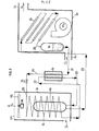
Sur la Figure 2 a été représenté un schéma de fonctionnement selon l'invention d'une pompe à chaleur air-air, destinée au chauffage de locaux, qui est illustré par l'éxemple 2. Le caisson D1, contrairement au caisson D2, est situé à l'extérieur du local à chauffer, (split system), mais il est clair que le procédé de l'invention peut être mis en oeuvre dans une installation monobloc.FIG. 2 shows an operating diagram according to the invention of an air-air heat pump, intended for space heating, which is illustrated by example p 2. The box D1, unlike the box D2 , is located outside the room to be heated (split system), but it is clear that the method of the invention can be implemented in a one-piece installation.
Le mélange détendu est partiellement vaporisé dans l'évaporateur E4. Dans l'évaporateur E4, il circule globalement à contre-courant de l'air extérieur (F1,F2). Cet air extérieur est aspiré à la base de l'enceinte Dl par le ventilateur hélicoïde VE1 entraîné par le moteur électrique Ml et il est rejeté à l'extérieur à travers la grille de protection GP1. L'évaporateur E4 peut être constitué, par exemple, par un tube muni d'ailettes ou d'aiguilles; de nature à améliorer l'échange et enroulé en .spirale. Le mélange liquide-vapeur sortant de l'évaporateur E4 par le conduit 22 achève de se vaporiser dans l'échangeur E5 au contact du mélange arrivant par le conduit 21 et sort de l'échangeur E5 par le conduit 20 à l'état surchauffé. Il passe alors dans le compresseur hermétique HK1 d'où il ressort comprimé par le conduit 23. Il entre ensuite dans l'échangeur E6 dans lequel il se condense en chauffant l'air d'un local, cet air (F3,F4) étant aspiré par le ventilateur centrifuge VE2 à la base de l'enceinte D2. L'échangeur E6 est formé de plusieurs batteries distinctes qui sont parcourues en série par le mélange qui circule globalement de haut en bas à contre-courant de l'air. Celui-ci est aspiré par la gaine d'admission G2 et ressort de l'enceinte D2 par la gaine de refoulement G3 et circule ainsi de bas en haut. Le fluide mixte condensé ressort par le conduit 25 et il est recueilli dans le ballon B2. Le fluide mixte liquide ressort par le conduit 21 et il est sous-refroidi. dans l'échangeur E5 en chauffant le fluide mixte qui se vaporise. Il repart par le conduit 24 par lequel il arrive au détendeur V2, d'où il est envoyé par le conduit 26 à l'évaporateur E4.The expanded mixture is partially vaporized in the evaporator E4. In the evaporator E4, it generally flows against the current of the outside air (F 1 , F 2 ). This outside air is sucked in at the base of the enclosure D1 by the helical fan VE1 driven by the electric motor Ml and it is discharged outside through the protective grid GP1. The evaporator E4 can be constituted, for example, by a tube provided with fins or needles; likely to improve the exchange and wound in .spirale. The liquid-vapor mixture leaving the evaporator E4 by the
D'autre part, une telle installation peut prélever de la chaleur sur de l'air extérieur, mais aussi sur de l'air extrait ou une combinaison d'air extérieur et d'air extrait. Dans ce dernier cas, les points d'introduction de l'air extrait et de l'air extérieur peuvent être différents.On the other hand, such an installation can take heat from outside air, but also from extracted air or a combination of outside air and extracted air. In the latter case, the points of introduction of the extracted air and the outside air may be different.
Le procédé selon l'invention peut être également mis en oeuvre dans une pompe à chaleur utilisant de l'air comme source de chaleur et chauffant de l'eau. Dans ce cas, le condenseur de la pompe à chaleur peut être constitué par exemple par un échangeur double tube opérant à contre-courant.The method according to the invention can also be implemented in a heat pump using air as a heat source and heating water. In this case, the condenser of the heat pump can be constituted for example by a double tube exchanger operating against the current.
Lorsque l'intervalle de température selon lequel évolue le fluide extérieur qui est chauffé au condenseur de la pompe à chaleur est particulièrement large en comparaison de l'intervalle de température selon lequel évolue le fluide extérieur qui sert de source de chaleur à l'évaporateur de la pompe à chaleur, il est possible de réduire l'intervalle de vaporisation en réalisant l'étape de vaporisation à deux niveaux successifs de pression. Une telle disposition est réalisée sur le schéma de fonctionnement qui est représenté sur la Figure 3 et qui est illustré par l'exemple 3.When the temperature range over which the external fluid which is heated at the heat pump condenser is particularly large in comparison with the temperature interval over which the external fluid which serves as the heat source for the heat evaporator changes With the heat pump, it is possible to reduce the vaporization interval by carrying out the vaporization step at two successive pressure levels. Such an arrangement is made on the operating diagram which is represented in FIG. 3 and which is illustrated by example 3.
Le fluide mixte de travail est partiellement vaporisé à un premier niveau de pression P dans l'échangeur E10, dans lequel il entre par le conduit 30 et ressort par le conduit 31 ; l'échange de chaleur dans E10 est effectué avec une première fraction du fluide extérieur constituant la source froide, arrivant par le tube 43 et repartant par le tube 44. La vaporisation du fluide mixte se'poursuit dans l'échangeur E11, dans lequel le fluide mixte entre en mélange liquide-vapeur par le conduit 31, repart par le conduit 32 et prélève la chaleur de vaporisation sur le fluide mixte liquide, qui circule à contre-courant, pénètre dans E11 par le conduit 41 et ressort par le conduit 42. Le mélange liquide-vapeur est évacué par le canal 32 dans le ballon B3, où les phases liquide et vapeur se séparent. La phase vapeur est évacuée par le tube 33 et est aspirée, toujours à la pression P1, à un étage intermédiaire du compresseur K2. La disposition décrite suppose donc que la compression est effectuée en au moins deux étages.The mixed working fluid is partially vaporized at a first pressure level P in the exchanger E10, into which it enters through the
A la sortie de B3, la phase liquide est évacuée par le conduit 34, sous-refroidie dans' l'échangeur E12, puis est envoyée par le conduit 35 à travers la vanne de détente V4, où elle est détendue jusqu'à la pression basse du cycle P21 inférieure à P1. Une fois détendu dans V4, le fluide mixte est envoyé par le conduit 36 dans l'échangeur E13 et en ressort à l'état liquide vapeur par le conduit 37. L'échangeur assure la vaporisation partielle du fluide mixte à la pression P2, en prélevant de la chaleur sur une deuxième fraction du fluide extérieur extrait de la source froide, arrivant par le tube 45 et ressortant par le tube 46.At the outlet of B3, the liquid phase is evacuated through
La fin de la vaporisation du fluide mixte et une surchauffe éventuelle est effectuée dans l'échangeur E12 ; le fluide mixte partiellement vaporisé entre dans E12 par le tube 37, en ressort par le tube 38 et prélève la chaleur nécessaire à la fin de vaporisation au liquide sous-refroidi qui entre par le conduit 34 et repart par le conduit 35.The end of the vaporization of the mixed fluid and possible overheating is carried out in the exchanger E12; the partially vaporized mixed fluid enters E12 through the
Les niveaux de pression P1 et P2 obtenus à l'aide des organes de détente V3 et V4 sont fixés de manière à ce que la température du mélange liquide vapeur à l'entrée de l'échangeur E13 soit voisine de la température du mélange liquide vapeur à l'entrée de l'échangeur E10. Il est clair qu'ainsi l'intervalle de température entre le début et la fin de vaporisation est réduit. Une conséquence directe en est qu'au lieu d'avoir à comprimer tout le mélange vapeur à partir du niveau de pression P2, il est possible de comprimer une fraction de ce mélange vapeur à partir du niveau de pression intermédiaire P1 supérieur au niveau de pression P2.The pressure levels P1 and P2 obtained using the expansion members V3 and V4 are fixed so that the temperature of the liquid vapor mixture at the inlet of the exchanger E13 is close to the temperature of the liquid vapor mixture at the entrance to the E10 interchange. It is therefore clear that the temperature interval between the start and the end of spraying is reduced. A direct consequence of this is that instead of having to compress the entire vapor mixture from the pressure level P2, it is possible to compress a fraction of this vapor mixture from the intermediate pressure level P1 greater than the pressure level P2.
Le fluide mixte vaporisé à la pression P2 est évacué vers le premier étage du compresseur Kl par la conduite 38 ; il est mélangé au cours de la compression avec le fluide mixte vaporisé à la pression P et aspiré par le conduit 33. Le mélange final est refoulé de K2 par le canal 39 à la pression P3'. qui est la pression haute du cycle (P3 > P > P2). Il est alors désurchauffé et condensé dans l'échangeur E14, en chauffant le fluide extérieur qui arrive à contre-courant par le conduit 47 et repart par le conduit 48.The mixed fluid vaporized at the pressure P 2 is evacuated to the first stage of the compressor K1 via
Le fluide mixte, une fois condensa, est recueilli par l'intermédiaire du tube 40 dans le ballon de stockage B4. Le fluide mixte liquide est évacué par le tube 41, est sous-refroidi dans l'échangeur E11, puis envoyé par le conduit 42 à la vanne V3. Là il est détendu jusqu'à la pression intermédiaire du cycle Pl.The mixed fluid, once condensed, is collected via the
Différents mélanges peuvent être utilisés, comme fluide mixte de travail, à condition de ne pas former d'azéotrope dans les conditions de fonctionnement de la pompe à chaleur. Le mélange peut être formé par exemple par un mélange d'hydrocarbures ou d'hydrocarbures halogénés du type "Fréons", ou encore d'alcools, de cétones, d'esters, éthers, amines. Il peut être avantageux, notamment pour des installations fonctionnant à des températures relativement élevées,d'utiliser un mélange d'eau et d'un constituant soluble dans l'eau, tel que l'ammoniac ou encore tel que le méthanol.Different mixtures can be used as mixed working fluid, provided that an azeotrope is not formed under the operating conditions of the heat pump. The mixture can be formed for example by a mixture of hydrocarbons or halogenated hydrocarbons of the "Freons" type, or alternatively of alcohols, ketones, esters, ethers, amines. It may be advantageous, in particular for installations operating at relatively high temperatures, to use a mixture of water and a water-soluble constituent, such as ammonia or even such as methanol.
Un domaine d'application particulièrement important du procédé selon l'invention concerne les applications au chauffage de locaux et notamment les pompes à chaleur équipant des habitations. L'invention s'applique également aux installations qui fonctionnent en pompe à chaleur en hiver et en conditionnement d'air en été et dans lesquelles le passage du fonctionnement "hiver" au fonctionnement "été" s'obtient par exemple en mettant en oeuvre une vanne d'inversion selon un principe bien connu en conditionnement d'air. Le procédé selon l'invention correspondant au schéma 3 est adapté à des applications du type chauffage industriel ou collectif, dans lesquelles la variation de température du fluide de chauffage est nettement plus grande que le refroidissement du fluide provenant de la source froide.A particularly important field of application of the method according to the invention relates to applications in space heating and in particular the heat pumps fitted to dwellings. The invention also applies to installations which operate as a heat pump in winter and in air conditioning in summer and in which the transition from "winter" operation to "summer" operation is obtained for example by implementing a reversing valve according to a well-known principle in air conditioning. The method according to the invention corresponding to diagram 3 is suitable for applications of the industrial or collective heating type, in which the temperature variation of the heating fluid is significantly greater than the cooling of the fluid from the cold source.
Dans les installations de chauffage ou de conditionnement de locaux, pour des raisons de sécurité, le mélange utilisé est généralement un mélange de constituants du type "Fréons". Les mélanges peuvent être ainsi formés par des mélanges binaires comportant un constituant majoritaire tel que le monochlorodifluorométhane (R-22), le dichlorofluorométhane (R-12), le chloropentafluoroéthane (R-115) ou encore un mélange azéotropique tel que le R-502, azéotrope de R-22 et de R-115 et un second constituant tel que le trichlorofluorométhane (R-11), le dichlorotétrafluoro- éthane (R-114), le dichlorohexafluoropropane (R-216), le dichlorofluorométhane (R-21), le monochlorotrifluorométhane (R-13), le trifluorométhane (R-23), le trifluorobromométhane (R-13B1). Des exemples spécifiques sont les suivants :![]()
![]()
![]()
![]()
![]()
![]()
![]()
![]()
Le réglage de l'organe de détente qui précède l'évaporateur doit être effectué en tenant compte de la composition du mélange. Dans les pompes à chaleur utilisées pour le chauffage de locaux, le détendeur est en général pourvu d'un bulbe qui contient le réfrigérant utilisé comme fluide de travail. La pression de détente obtenue correspond à une pression telle que le même réfrigérant à la température du bulbe est surchauffé de 5 à 15 °C ; cette surchauffe étant réglée en jouant sur le tarage du détendeur. Le même type de détendeur peut être:utilisé dans le cas d'un mélange. La pression après détente doit être toutefois réglée de manière à ce que le fluide mixte de travail ne soit que partiellement vaporisé au cours de l'échange avec le fluide extérieur qui sert de source de chaleur et sorte légèrement surchauffé de l'échangeur dans lequel il prélève de la chaleur sur le mélange sortant du condenseur. Ce réglage peut être effectué à la fois en jouant sur le tarage du détendeur et sur la position du bulbe ainsi que sur la nature du fluide qui remplit le bulbe qui peut être par exemple du R-22 ou du R-12. Le bulbe peut être placé en différents points et mis en équilibre de température avec le fluide mixte de travail par exemple à la fin de l'étape (e) ou à la fin de l'étape (f) ou à la fin de l'étape (c) ou encore en un point intermédiaire de l'une quelconque de ces étapes.The adjustment of the expansion device which precedes the evaporator must be carried out taking into account the composition of the mixture. In heat pumps used for space heating, the expansion valve is generally provided with a bulb which contains the refrigerant used as working fluid. The expansion pressure obtained corresponds to a pressure such that the same refrigerant at the bulb temperature is superheated from 5 to 15 ° C; this overheating being adjusted by adjusting the calibration of the regulator. The same type of regulator can be: used in the case of a mixture. The pressure after expansion must, however, be adjusted so that the mixed working fluid is only partially vaporized during the exchange with the external fluid which serves as a heat source and comes out slightly overheated from the exchanger in which it draws heat from the mixture leaving the condenser. This adjustment can be carried out both by adjusting the setting of the regulator and the position of the bulb as well as the nature of the fluid which fills the bulb which can be for example R-22 or R-12. The bulb can be placed at different points and brought into temperature equilibrium with the mixed working fluid, for example at the end of step (e) or at the end of step (f) or at the end of the step (c) or at an intermediate point in any one of these steps.
On conçoit qu'il est possible soit d'augmenter la pression si l'on constate que la surchauffe à la fin de l'étape (f) est excessive en déplaçant le bulbe vers un point dont la température est plus élevée, soit de diminuer la pression en déplaçant le bulbe vers un point dont la température est plus basse. En utilisant une telle disposition, il est possible d'obtenir un réglage automatique de la pression dans l'évaporateur en réponse à une variation de la température extérieure.It is understood that it is possible either to increase the pressure if it is found that the overheating at the end of step (f) is excessive by moving the bulb towards a point whose temperature is higher, or to decrease pressure by moving the bulb to a point with a lower temperature. By using such an arrangement, it is possible to obtain an automatic adjustment of the pressure in the evaporator in response to a variation in the outside temperature.
Les conditions de fonctionnement sont choisies en général de manière à ce que la pression du mélange dans l'évaporateur soit supérieure à la pression atmosphérique et que la pression du mélange dans le condenseur n'atteigne pas des valeurs excessives, par exemple supérieures à 30 bar.The operating conditions are generally chosen so that the pressure of the mixture in the evaporator is greater than atmospheric pressure and that the pressure of the mixture in the condenser does not reach excessive values, for example greater than 30 bar. .
La température d'entrée du fluide extérieur qui sert de source de chaleur est généralement supérieure à 0°C pendant au moins une partie de la durée de fonctionnement de la pompe à chaleur au cours de l'année.The inlet temperature of the external fluid which serves as a heat source is generally above 0 ° C for at least part of the operating time of the heat pump during the year.
L'appareil mettant en oeuvre le procédé peut être réalisé en utilisant différents équipements pour chacun des composants.The apparatus implementing the method can be carried out using different equipment for each of the components.
Ainsi l'échangeur dans lequel est effectuée l'étape finale de vaporisation qui s'effectue par échange avec le mélange sortant du condenseur peut être par exemple un échangeur double tube, différents types d'ailettes pouvant être introduits soit dans le ou les tubes intérieurs et l'espace annulaire entre le ou les tubes intérieurs et le tube extérieur. Dans ce cas, il pourra être avantageux de faire circuler le mélange sortant du condenseur dans le ou les tubes intérieurs de manière à obtenir des vitesses de passage plus élevées.Thus, the exchanger in which the final vaporization step is carried out, which is carried out by exchange with the mixture leaving the condenser, can for example be a double tube exchanger, different types of fins being able to be introduced either into the inner tube or tubes. and the annular space between the inner tube (s) and the outer tube. In this case, it may be advantageous to circulate the mixture leaving the condenser in the inner tube or tubes so as to obtain higher passage speeds.
Ledit échangeur pourra être également constitué par un échangeur à plaques planes ou encore en spirale, la seule condition à respecter étant de réaliser un échange qui soit le plus proche possible d'un contre-courant pur.Said exchanger may also be constituted by an exchanger with flat or spiral plates, the only condition to be observed being to carry out an exchange which is as close as possible to a pure counter-current.
Les échangeurs en contact avec les fluides extérieurs, c'est-à-dire l'évaporateur et le condenseur, peuvent être également de type quelcon- que à condition d'être adaptés à la nature du fluide extérieur avec lequel s'effectue l'échange.The exchangers in contact with the external fluids, that is to say the evaporator and the condenser, can also be of any type provided that they are adapted to the nature of the external fluid with which the exchange.
Le compresseur peut être par exemple un compresseur à piston lubrifié du type hermétique ou du type ouvert, un compresseur à piston sec ou pour des puissances supérieures, un compresseur à vis ou un compresseur centrifuge.The compressor can be for example a lubricated piston compressor of the hermetic or open type, a dry piston compressor or for higher powers, a screw compressor or a centrifugal compressor.
Les Figures 1, 2 et 3 qui servent à illustrer l'invention-ne constituent que des schémas de principe et ne font pas mention de certains éléments secondaires pouvant faire partie des installations usuelles de pompes à chaleur, tels que-voyants, cartouche séchante, bouteille anti- coup de liquide à l'entrée du compresseur, etc...Figures 1, 2 and 3 which serve to illustrate the invention-constitute only schematic diagrams and do not mention certain secondary elements which may form part of the usual installations of heat pumps, such as -indicators, drying cartridge, anti-liquid blow bottle at the compressor inlet, etc ...
Les exemples suivants illustrent la mise en oeuvre du procédé selon l'invention.The following examples illustrate the implementation of the method according to the invention.
L'exemple 1 est illustré par la Figure 1. La source froide est constituée par l'eau extraite d'une nappe phréatique. Cette eau, dont le débit est de 1500 1/h, arrive dans l'évaporateur El par le conduit 2 à une température de 12 °C et ressort de l'évaporateur El par le conduit 3 à une température de 5 °C. Au condenseur E3, l'eau de chauffage dont le débit est de 1000 1/h arrive par le conduit 10 à une température de 21,3 °C et ressort par le conduit 11 à une température de 34,5 °C.Example 1 is illustrated in Figure 1. The cold source is cons formed by water extracted from a water table. This water, the flow rate of which is 1500 l / h, arrives in the evaporator El via the
Le fluide de travail est un mélange binaire dont la composition molaire est la suivante :
![]()
![]()
Le mélange sort de l'évaporateur El à une température de 3,5 °C. La fraction molaire vaporisée à la sortie de El est 0,86. Le mélange finit de se vaporiser dans l'échangeur E2 à une température de 9,3 °C. On observe que l'introduction de l'échangeur E2 dans lequel le mélange sortant de l'évaporateur El finit de se vaporiser et dans lequel le mélange sortant du bac de réserve B1 est sous-refroidi permet à la fois d'augmenter le coefficient de performance de 6,1 % et de réduire le débit volumique à l'aspiration du compresseur de 4,4 %, par rapport à une installation identique ne comportant pas l'échangeur E2 et fonctionnant avec le même mélange.The mixture leaves the evaporator El at a temperature of 3.5 ° C. The molar fraction vaporized at the outlet of El is 0.86. The mixture finishes vaporizing in the exchanger E2 at a temperature of 9.3 ° C. It is observed that the introduction of the exchanger E2 in which the mixture leaving the evaporator El finishes vaporizing and in which the mixture leaving the reserve tank B1 is sub-cooled makes it possible both to increase the coefficient of 6.1% performance and reduce the volume flow rate at the compressor suction by 4.4%, compared to an identical installation without the E2 exchanger and operating with the same mixture.
L'exemple 2 est illustré par la Figure 2. L'évaporateur E4 reçoit un débit d'air extérieur de 4864 m3/h arrivant à une température de 8,3 °C-Cet air ressort à une température de 6,3 °C.- Le condenseur E6 permet le chauffage d'un débit de 1084 m3/h d'air provenant du local à chauffer, qui arrive sur le condenseur E6 à une température de 21,1 °C et ressort réchauffé à une température de 33,4 °C.Example 2 is illustrated in Figure 2. The evaporator E4 receives an outside air flow of 4864 m 3 / h arriving at a temperature of 8.3 ° C - This air comes out at a temperature of 6.3 ° C.- The condenser E6 allows the heating of a flow of 1084 m3 / h of air coming from the room to be heated, which arrives on the condenser E6 at a temperature of 21.1 ° C and comes out heated to a temperature of 33 , 4 ° C.
Le fluide de travail est un mélange ternaire dont la composition molaire est la suivante :

Le mélange sort de l'évaporateur E4 à une température de 0,6 °C. La fraction molaire vaporisée à la sortie de l'évaporateur E4 est 0,85. Le mélange finit de se vaporiser dans l'échangeur E5 à une température de 5,1 °C. L'introduction de l'échangeur E5 permet à la fois d'augmenter le coefficient de performance de.S,7 % et de réduire le débit volumique à l'aspiration du compresseur de 7,4 % par rapport à une installation identique ne comportant pas l'échangeur E5 et fonctionnant avec le même mélange.The mixture leaves the evaporator E4 at a temperature of 0.6 ° C. The molar fraction vaporized at the outlet of the evaporator E4 is 0.85. The mixture finishes vaporizing in the E5 exchanger at a temperature of 5.1 ° C. The introduction of the E5 exchanger allows both to increase the coefficient of performance of S. 7% and to reduce the volume flow at the compressor suction by 7.4% compared to an installation identical without the E5 exchanger and operating with the same mixture.
L'exemple 3 est illustré par la Figure 3. La source de chaleur aux évaporateurs E10 et E13 est constituée par de l'eau envoyée à 40 °C et refroidie jusqu'à 33 °C. Le débit d'eau circulant dans les évaporateurs E10 et E13 est identique et égal à 75 m3/h. Le fluide de chauffage qui est chauffé au condenseur E14 est de l'eau qui entre dans le condenseur E14 à une température de 45 °C et qui est réchauffée jusqu'à une température de 82 °C. Son débit est de 35 m3/h. Le fluide de travail est un mélange binaire équimolaire constitué de dichlorodifluorométhane (R-12) et de trichlorotrifluoroéthane (R-113). Le compresseur est un compresseur du type centrifuge à deux étages. Le premier étage aspire le mé- - lange vapeur à une pression de 1,31 bar et le refoule à une pression intermédiaire de 2,49 bar. Le second étage comprime le mélange sortant du premier étage et le mélange arrivant par le conduit 33 jusqu'à une pression finale de 6,54 bar.Example 3 is illustrated in Figure 3. The heat source to the evaporators E10 and E13 consists of water sent to 40 ° C and cooled to 33 ° C. The water flow circulating in the evaporators E10 and E13 is identical and equal to 75 m 3 / h. The heating fluid which is heated in the condenser E14 is water which enters the condenser E14 at a temperature of 45 ° C and which is reheated to a temperature of 82 ° C. Its flow is 35 m 3 / h. The working fluid is an equimolar binary mixture consisting of dichlorodifluoromethane ( R -12) and trichlorotrifluoroethane (R-113). The compressor is a two-stage centrifugal type compressor. The first stage sucks in the steam mixture at a pressure of 1.31 bar and discharges it at an intermediate pressure of 2.49 bar. The second stage compresses the mixture leaving the first stage and the mixture arriving via
Le mélange liquide sous-refroidi sortant de l'échangeur E11 par le conduit 42 commence à se vaporiser dans l'évaporateur E10. Par rapport au débit liquide de la conduite 41 on constate que, à la sortie de l'évaporateur E10, la fraction vaporisée est de 0,4 en fraction molaire à la sortie de l'évaporateur Ell, elle est de 0,5 en fraction molaire à la sortie de l'évaporateur E13 la fraction vaporisée est au total de 0,8 en fraction molaire (soit 0,3 dans l'évaporateur E13). La vaporisation s'achève complètement dans l'évaporateur E12The sub-cooled liquid mixture leaving the exchanger E11 via the
L'intervalle de condensation dans l'échangeur E14 est de 39 °C alors que les intervalles de vaporisation à basse pression (vaporisation opérée dans les échangeurs E13 et E12) et à pression intermédiaire (vaporisation opérée dans les échangeurs E10 et Ell) sont voisins de 18 °C. On vérifie ainsi que la disposition schématisée sur la Figure 3 permet de récupérer de la chaleur sur un intervalle de température beaucoup plus réduit que l'intervalle de température suivant lequel elle est fournie, en opérant des échanges de chaleur dans de bonnes conditions de réversibilité. Il s'ensuit un gain sur le coefficient de performance qui, dans l'exemple considéré, est d'environ 25 % par rapport à un cycle comprenant un seul évaporateur et utilisant le même mélange.The condensation interval in the exchanger E 14 is 39 ° C. while the vaporization intervals at low pressure (vaporization operated in exchangers E13 and E12) and at intermediate pressure (vaporization operated in exchangers E10 and Ell) are neighbors of 18 ° C. It is thus verified that the arrangement shown diagrammatically in FIG. 3 makes it possible to recover heat over a temperature interval much smaller than the temperature interval according to which it is supplied, by operating heat exchanges under good conditions of reversibility. This results in a gain on the coefficient of performance which, in the example considered, is approximately 25% compared to a cycle comprising a single evaporator and using the same mixture.
Claims (12)
Priority Applications (1)
| Application Number | Priority Date | Filing Date | Title |
|---|---|---|---|
| AT82400042T ATE17273T1 (en) | 1981-01-15 | 1982-01-11 | METHOD OF HEATING A SPACE USING A COMPRESSION HEAT PUMP USING A MIXTURE AS THE WORKING FLUID. |
Applications Claiming Priority (2)
| Application Number | Priority Date | Filing Date | Title |
|---|---|---|---|
| FR8100847 | 1981-01-15 | ||
| FR8100847A FR2497931A1 (en) | 1981-01-15 | 1981-01-15 | METHOD FOR HEATING AND HEAT CONDITIONING USING A COMPRESSION HEAT PUMP OPERATING WITH A MIXED WORKING FLUID AND APPARATUS FOR CARRYING OUT SAID METHOD |
Publications (3)
| Publication Number | Publication Date |
|---|---|
| EP0057120A2 true EP0057120A2 (en) | 1982-08-04 |
| EP0057120A3 EP0057120A3 (en) | 1983-05-04 |
| EP0057120B1 EP0057120B1 (en) | 1986-01-02 |
Family
ID=9254262
Family Applications (1)
| Application Number | Title | Priority Date | Filing Date |
|---|---|---|---|
| EP82400042A Expired EP0057120B1 (en) | 1981-01-15 | 1982-01-11 | Method of heating a room by means of a compression heat pump using a mixed working medium |
Country Status (6)
| Country | Link |
|---|---|
| US (1) | US4406135A (en) |
| EP (1) | EP0057120B1 (en) |
| JP (1) | JPS57184860A (en) |
| AT (1) | ATE17273T1 (en) |
| DE (1) | DE3268192D1 (en) |
| FR (1) | FR2497931A1 (en) |
Cited By (6)
| Publication number | Priority date | Publication date | Assignee | Title |
|---|---|---|---|---|
| EP0174027A2 (en) * | 1984-09-06 | 1986-03-12 | Matsushita Electric Industrial Co., Ltd. | Heat pump apparatus |
| EP0192496A1 (en) * | 1985-01-09 | 1986-08-27 | Institut Français du Pétrole | Cold and/or heat production process using a non-azeotropic mixture of fluids in an ejector cycle |
| FR2578638A1 (en) * | 1985-03-08 | 1986-09-12 | Inst Francais Du Petrole | METHOD FOR TRANSFERRING HEAT FROM A HOT FLUID TO A COLD FLUID USING A MIXED FLUID AS A HEAT EXCHANGER |
| EP0248296A2 (en) * | 1986-05-23 | 1987-12-09 | Energiagazdálkodási Részvénytársaság | Method for increasing the coefficient of performance of hybrid refrigeration machines or heat pumps |
| EP0179225B1 (en) * | 1984-09-19 | 1988-10-19 | Kabushiki Kaisha Toshiba | Heat pump system |
| DE3922950A1 (en) * | 1989-07-12 | 1991-01-17 | Mayer Schuh Gmbh | Ski boot with hard shell - has slide guides and strap ports linked by tension device |
Families Citing this family (16)
| Publication number | Priority date | Publication date | Assignee | Title |
|---|---|---|---|---|
| JPS59157446A (en) * | 1983-02-22 | 1984-09-06 | 松下電器産業株式会社 | Refrigeration cycle device |
| FR2561363B1 (en) * | 1984-03-14 | 1987-03-20 | Inst Francais Du Petrole | PROCESS FOR IMPLEMENTING A HEAT PUMP AND / OR A REFRIGERATION COMPRESSION MACHINE HAVING PERIODIC DEFROSTING BY CYCLE INVERSION |
| FR2564955B1 (en) * | 1984-05-28 | 1987-03-20 | Inst Francais Du Petrole | PROCESS FOR PRODUCING HEAT AND / OR COLD USING A COMPRESSION MACHINE OPERATING WITH A MIXED WORKING FLUID |
| JPS6166053A (en) * | 1984-09-06 | 1986-04-04 | 松下電器産業株式会社 | Heat pump device |
| HU198328B (en) * | 1984-12-03 | 1989-09-28 | Energiagazdalkodasi Intezet | Method for multiple-stage operating hibrid (compression-absorption) heat pumps or coolers |
| US4724679A (en) * | 1986-07-02 | 1988-02-16 | Reinhard Radermacher | Advanced vapor compression heat pump cycle utilizing non-azeotropic working fluid mixtures |
| FR2607142B1 (en) * | 1986-11-21 | 1989-04-28 | Inst Francais Du Petrole | MIXTURE OF WORKING FLUIDS FOR USE IN COMPRESSION THERMODYNAMIC CYCLES COMPRISING TRIFLUOROMETHANE AND CHLORODIFLUOROETHANE |
| US5237828A (en) * | 1989-11-22 | 1993-08-24 | Nippondenso Co., Ltd. | Air-conditioner for an automobile with non-azeotropic refrigerant mixture used to generate "cool head" and "warm feet" profile |
| US5076064A (en) * | 1990-10-31 | 1991-12-31 | York International Corporation | Method and refrigerants for replacing existing refrigerants in centrifugal compressors |
| CH691743A5 (en) * | 1996-04-01 | 2001-09-28 | Satag Thermotechnik Ag | Plant for power conversion by the cold vapor compression process. |
| US8769972B2 (en) * | 2008-12-02 | 2014-07-08 | Xergy Inc | Electrochemical compressor and refrigeration system |
| US11118816B2 (en) * | 2009-05-01 | 2021-09-14 | Xergy Inc. | Advanced system for electrochemical cell |
| US9464822B2 (en) * | 2010-02-17 | 2016-10-11 | Xergy Ltd | Electrochemical heat transfer system |
| GB2482629B (en) * | 2009-05-01 | 2015-04-08 | Xergy Inc | Self-contained electrochemical heat transfer system |
| DE102013211084A1 (en) * | 2013-06-14 | 2014-12-18 | Siemens Aktiengesellschaft | Method for operating a heat pump and heat pump |
| WO2018017980A1 (en) | 2016-07-21 | 2018-01-25 | Exency Ltd. | Exploiting internally generated heat in heat engines |
Citations (11)
| Publication number | Priority date | Publication date | Assignee | Title |
|---|---|---|---|---|
| US2255585A (en) * | 1937-12-27 | 1941-09-09 | Borg Warner | Method of and apparatus for heat transfer |
| US2255584A (en) * | 1937-12-11 | 1941-09-09 | Borg Warner | Method of and apparatus for heat transfer |
| FR973795A (en) * | 1947-10-20 | 1951-02-14 | Petrocarbon Ltd | Improvements in refrigeration processes and devices |
| US2794329A (en) * | 1954-06-29 | 1957-06-04 | Gen Electric | Variable temperature refrigeration |
| US2952139A (en) * | 1957-08-16 | 1960-09-13 | Patrick B Kennedy | Refrigeration system especially for very low temperature |
| FR2177785A1 (en) * | 1972-03-24 | 1973-11-09 | Monsator Haushaltsgrossgeraete | |
| US3889485A (en) * | 1973-12-10 | 1975-06-17 | Judson S Swearingen | Process and apparatus for low temperature refrigeration |
| FR2296827A1 (en) * | 1974-12-31 | 1976-07-30 | Vignal Maurice | Heat pump circulation system - has heat exchanger with cooling and heating passages connecting compressor condenser and expander unit |
| FR2337855A1 (en) * | 1976-01-07 | 1977-08-05 | Inst Francais Du Petrole | HEAT PRODUCTION PROCESS USING A HEAT PUMP OPERATING WITH A MIXTURE OF FLUIDS |
| FR2356097A1 (en) * | 1976-06-23 | 1978-01-20 | Krieger Heinrich | PROCESS AND INSTALLATION FOR PRODUCING COLD WITH AT LEAST ONE INCORPORATED CASCADE CIRCUIT |
| EP0021205A2 (en) * | 1979-06-08 | 1981-01-07 | Energiagazdalkodasi Intezet | Hybrid compression-absorption method for operating heat pumps or refrigeration machines |
Family Cites Families (10)
| Publication number | Priority date | Publication date | Assignee | Title |
|---|---|---|---|---|
| US2041725A (en) * | 1934-07-14 | 1936-05-26 | Walter J Podbielniak | Art of refrigeration |
| US2581558A (en) * | 1947-10-20 | 1952-01-08 | Petrocarbon Ltd | Plural stage cooling machine |
| US2794328A (en) * | 1954-06-29 | 1957-06-04 | Gen Electric | Variable temperature refrigeration |
| US2841965A (en) * | 1954-06-29 | 1958-07-08 | Gen Electric | Dual capacity refrigeration |
| US2867094A (en) * | 1954-09-30 | 1959-01-06 | Gen Electric | Variable temperature refrigeration |
| DE1241468B (en) * | 1962-12-01 | 1967-06-01 | Andrija Fuderer Dr Ing | Compression method for generating cold |
| US4167101A (en) * | 1975-08-14 | 1979-09-11 | Institut Francais Du Petrole | Absorption process for heat conversion |
| FR2474151A1 (en) * | 1980-01-21 | 1981-07-24 | Inst Francais Du Petrole | METHOD OF PRODUCING HEAT USING A HEAT PUMP USING A SPECIFIC MIXTURE OF FLUIDS AS A WORKING AGENT |
| FR2476287A1 (en) * | 1980-02-15 | 1981-08-21 | Inst Francais Du Petrole | METHOD FOR THE PRODUCTION OF COLD AND / OR HEAT BY ABSORPTION CYCLE FOR USE IN PARTICULAR FOR THE HEATING OF PREMISES |
| SU1035354A1 (en) * | 1980-10-16 | 1983-08-15 | Всесоюзный Научно-Исследовательский Экспериментально-Конструкторский Институт Электробытовых Машин И Приборов | Method of creating refrigeration in single-stage compression refrigerating machine |
-
1981
- 1981-01-15 FR FR8100847A patent/FR2497931A1/en active Granted
-
1982
- 1982-01-11 EP EP82400042A patent/EP0057120B1/en not_active Expired
- 1982-01-11 AT AT82400042T patent/ATE17273T1/en not_active IP Right Cessation
- 1982-01-11 DE DE8282400042T patent/DE3268192D1/en not_active Expired
- 1982-01-14 JP JP57004778A patent/JPS57184860A/en active Pending
- 1982-01-15 US US06/339,565 patent/US4406135A/en not_active Expired - Fee Related
Patent Citations (11)
| Publication number | Priority date | Publication date | Assignee | Title |
|---|---|---|---|---|
| US2255584A (en) * | 1937-12-11 | 1941-09-09 | Borg Warner | Method of and apparatus for heat transfer |
| US2255585A (en) * | 1937-12-27 | 1941-09-09 | Borg Warner | Method of and apparatus for heat transfer |
| FR973795A (en) * | 1947-10-20 | 1951-02-14 | Petrocarbon Ltd | Improvements in refrigeration processes and devices |
| US2794329A (en) * | 1954-06-29 | 1957-06-04 | Gen Electric | Variable temperature refrigeration |
| US2952139A (en) * | 1957-08-16 | 1960-09-13 | Patrick B Kennedy | Refrigeration system especially for very low temperature |
| FR2177785A1 (en) * | 1972-03-24 | 1973-11-09 | Monsator Haushaltsgrossgeraete | |
| US3889485A (en) * | 1973-12-10 | 1975-06-17 | Judson S Swearingen | Process and apparatus for low temperature refrigeration |
| FR2296827A1 (en) * | 1974-12-31 | 1976-07-30 | Vignal Maurice | Heat pump circulation system - has heat exchanger with cooling and heating passages connecting compressor condenser and expander unit |
| FR2337855A1 (en) * | 1976-01-07 | 1977-08-05 | Inst Francais Du Petrole | HEAT PRODUCTION PROCESS USING A HEAT PUMP OPERATING WITH A MIXTURE OF FLUIDS |
| FR2356097A1 (en) * | 1976-06-23 | 1978-01-20 | Krieger Heinrich | PROCESS AND INSTALLATION FOR PRODUCING COLD WITH AT LEAST ONE INCORPORATED CASCADE CIRCUIT |
| EP0021205A2 (en) * | 1979-06-08 | 1981-01-07 | Energiagazdalkodasi Intezet | Hybrid compression-absorption method for operating heat pumps or refrigeration machines |
Cited By (9)
| Publication number | Priority date | Publication date | Assignee | Title |
|---|---|---|---|---|
| EP0174027A2 (en) * | 1984-09-06 | 1986-03-12 | Matsushita Electric Industrial Co., Ltd. | Heat pump apparatus |
| EP0174027A3 (en) * | 1984-09-06 | 1987-12-23 | Matsushita Electric Industrial Co., Ltd. | Heat pump apparatus |
| EP0179225B1 (en) * | 1984-09-19 | 1988-10-19 | Kabushiki Kaisha Toshiba | Heat pump system |
| EP0192496A1 (en) * | 1985-01-09 | 1986-08-27 | Institut Français du Pétrole | Cold and/or heat production process using a non-azeotropic mixture of fluids in an ejector cycle |
| FR2578638A1 (en) * | 1985-03-08 | 1986-09-12 | Inst Francais Du Petrole | METHOD FOR TRANSFERRING HEAT FROM A HOT FLUID TO A COLD FLUID USING A MIXED FLUID AS A HEAT EXCHANGER |
| EP0195704A1 (en) * | 1985-03-08 | 1986-09-24 | Institut Français du Pétrole | Heat exchange process between a warm and a cold fluid using a mixed fluid as the working fluid |
| EP0248296A2 (en) * | 1986-05-23 | 1987-12-09 | Energiagazdálkodási Részvénytársaság | Method for increasing the coefficient of performance of hybrid refrigeration machines or heat pumps |
| EP0248296A3 (en) * | 1986-05-23 | 1988-05-25 | Energiagazdalkodasi Intezet | Method and device for increasing the coefficient of performance of hybrid refrigeration machines or heat pumps |
| DE3922950A1 (en) * | 1989-07-12 | 1991-01-17 | Mayer Schuh Gmbh | Ski boot with hard shell - has slide guides and strap ports linked by tension device |
Also Published As
| Publication number | Publication date |
|---|---|
| JPS57184860A (en) | 1982-11-13 |
| EP0057120A3 (en) | 1983-05-04 |
| FR2497931B1 (en) | 1984-09-28 |
| EP0057120B1 (en) | 1986-01-02 |
| FR2497931A1 (en) | 1982-07-16 |
| ATE17273T1 (en) | 1986-01-15 |
| DE3268192D1 (en) | 1986-02-20 |
| US4406135A (en) | 1983-09-27 |
Similar Documents
| Publication | Publication Date | Title |
|---|---|---|
| EP0057120B1 (en) | Method of heating a room by means of a compression heat pump using a mixed working medium | |
| EP1355716B1 (en) | Method and system for extracting carbon dioxide by anti-sublimation for storage thereof | |
| CA1172054A (en) | Method for producing heat by means of a heat pump using a mixture of fluids as working agents and air as heat source | |
| FR2476240A1 (en) | ENERGY RECOVERY APPARATUS FOR GAS COMPRESSOR INSTALLATION | |
| EP0041005A1 (en) | Method for mechanical energy production from heat using a mixture of fluids as the working fluid | |
| FR2514875A1 (en) | METHOD OF HEATING AND / OR THERMALLY CONDITIONING A LOCAL USING A COMPRESSION HEAT PUMP USING A SPECIFIC MIXTURE OF WORKING FLUIDS | |
| CA1295140C (en) | Absorption heat and cold production process using a combination of components as woeking fluid | |
| EP0192496B1 (en) | Cold and/or heat production process using a non-azeotropic mixture of fluids in an ejector cycle | |
| WO2019110628A1 (en) | System and method for cooling a gas stream by means of an evaporator | |
| EP0081395B1 (en) | Fluid for a heat pump and process for treating and/or thermally conditioning a room by means of a compression heat pump using a specific mixture of working fluids | |
| EP0956485A1 (en) | Absorption refrigerating system and working mixture for said system | |
| EP0272953A1 (en) | Mixtures of working fluids for use in thermodynamic compression cycles, comprising trifluoromethane and chlorodifluoroethane | |
| EP2411743B1 (en) | Installation and method for the production of cold and/or heat | |
| US20060242974A1 (en) | Evaporation process control for use in refrigeration technology | |
| WO2016146858A1 (en) | Reversible thermodynamic device for heat transfer | |
| FR2944096A1 (en) | METHOD AND REFRIGERATING SYSTEM FOR RECOVERING METHANE COLOR WITH REFRIGERATED FLUIDS | |
| FR3075934A1 (en) | AIR PROCESSING CENTER COMPRISING AN ABSORPTION DEVICE AND ASSOCIATED METHOD | |
| CA2630886A1 (en) | Method and system for recovering energy through air conditioning | |
| FR2699087A1 (en) | Improved distn column system - having a heat pump on the heat exchanger of a non-adiabatic column | |
| FR2508617A1 (en) | METHOD AND APPARATUS FOR EXTRACTING THERMAL ENERGY FROM A SUBSTANCE | |
| WO2022229293A1 (en) | Heat pump and phase-change energy storage device | |
| FR2683301A1 (en) | Mixed compression/absorption refrigeration device | |
| DK178705B1 (en) | A heat pump system using water as the thermal fluid | |
| FR2692343A1 (en) | Large refrigeration system with two-stage compression e.g. for use in hypermarket - uses high and low pressure circuits with heat exchanger between them to limit heating of refrigerant. | |
| EP4325150A1 (en) | Method and apparatus for cooling hydrogen |
Legal Events
| Date | Code | Title | Description |
|---|---|---|---|
| PUAI | Public reference made under article 153(3) epc to a published international application that has entered the european phase |
Free format text: ORIGINAL CODE: 0009012 |
|
| AK | Designated contracting states |
Designated state(s): AT BE CH DE GB IT NL SE |
|
| PUAL | Search report despatched |
Free format text: ORIGINAL CODE: 0009013 |
|
| AK | Designated contracting states |
Designated state(s): AT BE CH DE GB IT LI NL SE |
|
| 17P | Request for examination filed |
Effective date: 19830930 |
|
| ITF | It: translation for a ep patent filed |
Owner name: ST. ASSOC. MARIETTI & PIPPARELLI |
|
| GRAA | (expected) grant |
Free format text: ORIGINAL CODE: 0009210 |
|
| AK | Designated contracting states |
Designated state(s): AT BE CH DE GB IT LI NL SE |
|
| REF | Corresponds to: |
Ref document number: 17273 Country of ref document: AT Date of ref document: 19860115 Kind code of ref document: T |
|
| REF | Corresponds to: |
Ref document number: 3268192 Country of ref document: DE Date of ref document: 19860220 |
|
| PLBE | No opposition filed within time limit |
Free format text: ORIGINAL CODE: 0009261 |
|
| STAA | Information on the status of an ep patent application or granted ep patent |
Free format text: STATUS: NO OPPOSITION FILED WITHIN TIME LIMIT |
|
| 26N | No opposition filed | ||
| PGFP | Annual fee paid to national office [announced via postgrant information from national office to epo] |
Ref country code: NL Payment date: 19890131 Year of fee payment: 10 |
|
| PGFP | Annual fee paid to national office [announced via postgrant information from national office to epo] |
Ref country code: AT Payment date: 19910103 Year of fee payment: 10 |
|
| PGFP | Annual fee paid to national office [announced via postgrant information from national office to epo] |
Ref country code: BE Payment date: 19910111 Year of fee payment: 10 |
|
| ITTA | It: last paid annual fee | ||
| PGFP | Annual fee paid to national office [announced via postgrant information from national office to epo] |
Ref country code: CH Payment date: 19910308 Year of fee payment: 10 |
|
| PG25 | Lapsed in a contracting state [announced via postgrant information from national office to epo] |
Ref country code: AT Effective date: 19920111 |
|
| PG25 | Lapsed in a contracting state [announced via postgrant information from national office to epo] |
Ref country code: LI Effective date: 19920131 Ref country code: CH Effective date: 19920131 Ref country code: BE Effective date: 19920131 |
|
| BERE | Be: lapsed |
Owner name: INSTITUT FRANCAIS DU PETROLE Effective date: 19920131 |
|
| PG25 | Lapsed in a contracting state [announced via postgrant information from national office to epo] |
Ref country code: NL Effective date: 19920801 |
|
| NLV4 | Nl: lapsed or anulled due to non-payment of the annual fee | ||
| REG | Reference to a national code |
Ref country code: CH Ref legal event code: PL |
|
| PGFP | Annual fee paid to national office [announced via postgrant information from national office to epo] |
Ref country code: GB Payment date: 19921223 Year of fee payment: 12 |
|
| PGFP | Annual fee paid to national office [announced via postgrant information from national office to epo] |
Ref country code: SE Payment date: 19930107 Year of fee payment: 12 |
|
| PGFP | Annual fee paid to national office [announced via postgrant information from national office to epo] |
Ref country code: DE Payment date: 19930306 Year of fee payment: 12 |
|
| PG25 | Lapsed in a contracting state [announced via postgrant information from national office to epo] |
Ref country code: GB Effective date: 19940111 |
|
| PG25 | Lapsed in a contracting state [announced via postgrant information from national office to epo] |
Ref country code: SE Effective date: 19940112 |
|
| GBPC | Gb: european patent ceased through non-payment of renewal fee |
Effective date: 19940111 |
|
| PG25 | Lapsed in a contracting state [announced via postgrant information from national office to epo] |
Ref country code: DE Effective date: 19941001 |
|
| EUG | Se: european patent has lapsed |
Ref document number: 82400042.6 Effective date: 19940810 |