EP0057099B1 - Vorrichtung zum kontinuierlichen Formen von zylinderförmigen Blöcken aus Kunstharzschaum - Google Patents
Vorrichtung zum kontinuierlichen Formen von zylinderförmigen Blöcken aus Kunstharzschaum Download PDFInfo
- Publication number
- EP0057099B1 EP0057099B1 EP82300363A EP82300363A EP0057099B1 EP 0057099 B1 EP0057099 B1 EP 0057099B1 EP 82300363 A EP82300363 A EP 82300363A EP 82300363 A EP82300363 A EP 82300363A EP 0057099 B1 EP0057099 B1 EP 0057099B1
- Authority
- EP
- European Patent Office
- Prior art keywords
- trough
- web
- webs
- section
- foam
- Prior art date
- Legal status (The legal status is an assumption and is not a legal conclusion. Google has not performed a legal analysis and makes no representation as to the accuracy of the status listed.)
- Expired
Links
- 238000000465 moulding Methods 0.000 title claims abstract description 17
- 239000000463 material Substances 0.000 title claims abstract description 10
- 238000005187 foaming Methods 0.000 claims abstract description 11
- 238000011144 upstream manufacturing Methods 0.000 claims abstract description 6
- 239000006260 foam Substances 0.000 claims description 16
- 239000003153 chemical reaction reagent Substances 0.000 claims description 14
- 238000004519 manufacturing process Methods 0.000 claims description 3
- 239000000203 mixture Substances 0.000 claims description 3
- 230000037303 wrinkles Effects 0.000 claims description 2
- 238000007493 shaping process Methods 0.000 claims 4
- 150000001875 compounds Chemical class 0.000 claims 2
- 230000001419 dependent effect Effects 0.000 claims 1
- 230000009969 flowable effect Effects 0.000 claims 1
- 229920005830 Polyurethane Foam Polymers 0.000 abstract description 3
- 239000011496 polyurethane foam Substances 0.000 abstract description 3
- 238000000926 separation method Methods 0.000 abstract description 3
- 229920002635 polyurethane Polymers 0.000 description 4
- 239000004814 polyurethane Substances 0.000 description 4
- 238000010097 foam moulding Methods 0.000 description 3
- 239000007788 liquid Substances 0.000 description 2
- 230000015572 biosynthetic process Effects 0.000 description 1
- 238000006243 chemical reaction Methods 0.000 description 1
- 239000008258 liquid foam Substances 0.000 description 1
- 238000000034 method Methods 0.000 description 1
- 239000002699 waste material Substances 0.000 description 1
Images

Classifications
-
- B—PERFORMING OPERATIONS; TRANSPORTING
- B29—WORKING OF PLASTICS; WORKING OF SUBSTANCES IN A PLASTIC STATE IN GENERAL
- B29C—SHAPING OR JOINING OF PLASTICS; SHAPING OF MATERIAL IN A PLASTIC STATE, NOT OTHERWISE PROVIDED FOR; AFTER-TREATMENT OF THE SHAPED PRODUCTS, e.g. REPAIRING
- B29C44/00—Shaping by internal pressure generated in the material, e.g. swelling or foaming ; Producing porous or cellular expanded plastics articles
- B29C44/20—Shaping by internal pressure generated in the material, e.g. swelling or foaming ; Producing porous or cellular expanded plastics articles for articles of indefinite length
- B29C44/32—Incorporating or moulding on preformed parts, e.g. linings, inserts or reinforcements
- B29C44/322—Incorporating or moulding on preformed parts, e.g. linings, inserts or reinforcements the preformed parts being elongated inserts, e.g. cables
- B29C44/324—Incorporating or moulding on preformed parts, e.g. linings, inserts or reinforcements the preformed parts being elongated inserts, e.g. cables the preformed parts being tubular or folded to a tubular shape
-
- Y—GENERAL TAGGING OF NEW TECHNOLOGICAL DEVELOPMENTS; GENERAL TAGGING OF CROSS-SECTIONAL TECHNOLOGIES SPANNING OVER SEVERAL SECTIONS OF THE IPC; TECHNICAL SUBJECTS COVERED BY FORMER USPC CROSS-REFERENCE ART COLLECTIONS [XRACs] AND DIGESTS
- Y10—TECHNICAL SUBJECTS COVERED BY FORMER USPC
- Y10S—TECHNICAL SUBJECTS COVERED BY FORMER USPC CROSS-REFERENCE ART COLLECTIONS [XRACs] AND DIGESTS
- Y10S264/00—Plastic and nonmetallic article shaping or treating: processes
- Y10S264/84—Conversion of foamed resinous buns into foamed billets having geo metrical crosssections
Definitions
- the present invention relates to an apparatus for continuously molding cylindrical blocks of foamed polymeric material, and more particularly, foamed polyurethane blocks for subsequent conversion into sheeting by a process of peeling.
- Liquid foam reagents are deposited at the first stage where the webs engage and then enter the molding channel.
- a U-shaped weir structure shapes the base web to its arcuate form and assists the engagement of the opposing webs and the guiding to the molding channel, the weir structure also holds back a portion of the liquid reagent mixture until foaming begins.
- US-A-3 786 122 describes the production of rectangular cross-section blocks of polyurethane foam. It is also describes a solution in relation to the problem of reducing the length of the conveyor and to overcoming the need for complicated feed head arrangements. The solution is to provide an upright molding trough at the leading edge of the conveyor. The trough is of rectangular cross-section, and a weir structure is provided in which an initial rectangular shape is given to the expanding foam polyurethane as it flows onto the conveyor. US-A-4 093 109 is also directed to such an apparatus.
- an apparatus for continuously manufacturing a foam block comprising an upstanding trough for preforming a mixture of polymeric foam reagents, the trough being of rectangular cross-section and having a longitudinal axis extending at right angles to the molding direction, the trough having an upwardly widening cavity terminating in a mouth having a flat flange along one longitudinal edge and directed towards the molding direction.
- the apparatus is characterized by the bottom of the trough having a uniform arcuate cross-section in a lateral plane; and by a feed inlet to the trough having an axis parallel to the longitudinal axis of the trough, the feed inlet being provided at the bottom of the trough and having a diameter generally the same as the diameter of the arcuate cross-section of the bottom of the trough whereby reagents are fed into the trough with a minimum of turbulence.
- a molding apparatus for polymeric foam includes a fall plate which is at an angle to the horizontal, a paper web feeding device for supplying a separation sheet surrounding the foaming polymeric material, and a conveyor of considerable length including shape- forming mold elements thereon for forming the contour of the block as it is being foamed and for drawing the separation sheet surrounding the block.
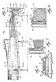
- the drawings of the present specification illustrate the upstream end of such a molding apparatus, including a prefoaming trough 12 for feeding the polymeric material P onto the fall plate 14 and including the initial web feeding apparatus 16 and 18.
- the trough 12 includes a rear wall 20, a bottom wall 22, an upwardly sloping wall 24 and a front wall 26.
- the front wall 26 is of reduced height compared to the rear wall 20 and terminates in a downstream extending flat flange 32 forming the weir.
- the trough 12 also has end walls 28 and 30. End walls 28 and 30 extend to the same heighfas rear wall 20 and includes forwardly projecting extensions 34 and 36 which are integral with opposed edges of the flange 32.
- the trough 12 also includes an inlet31 through which the reagents are fed into the trough 12.
- the inlet 31 is strategically located in end wall 28, and at the bottom of the trough adjacent the bottom wall 22.
- the bottom wall 22 has a curvature generally of the same diameter as the diameter of the inlet pipe 31.
- the fall plate 14 includes a table supported by support legs 38 and 40, and the table includes a fall plate surface 42 set at an angle to the horizontal.
- the setting of the angle ofthe fall plate is based on well-known criteria, including conveyor velocity characteristics of the foaming reagents, etc.
- a paper feed supply (not shown) is positioned behind the rear wall 20 of the trough 12.
- the paper web 44 is drawn below the trough 12 about the roller 46.
- the paper is then drawn over roller 48 which is immediately below the flange 32 and aligns the paper with the surface 42 ofthe fall plate 14.
- the paper passes through the gap 50 formed between the flange 32 and the leading edge 43 of the fall plate surface 42.
- a pair of wire frames 52 and 54 are provided on either side of the weir structure formed by the flange 32 to initially form the paper web which is coming off a flat paper roll, into a generally channel shaped cross-section.
- the roll 48 has a length which is shorter than the width of the paper web 44, and the wire frame members 52 and 54 are arranged to engage the paperweb 44 immediately adjacent the ends of the roll 48 so as to begin the formation of the channel shaped cross-section of the web 4 and to avoid the creation of wrinkles in the paper web.
- the wire frame members each include diverging arms which direct the paper web as shown.
- the side and bottom conveyors including the mold members 63, immediately engage the three paper webs and the foaming material P downstream of the paper supply rolls 56 and 58 so as to mold the foam product into a cylindrical form and to draw the paper web and the foam product down the foaming zone on the conveyor.
- the side molds could also be stationary, and the paper webs could be pulled therethrough.
- the foaming reagents are fed under controlled conditions through the inlet 31 into the trough 12.
- the reagents begin their foaming action within the trough 12, and foaming material P passes over theweirand immediatelyflows onto the first paper web 44 as it advances between the wire forms 52 and 54 in a channel shaped cross-section.
- foaming material P passes over theweirand immediatelyflows onto the first paper web 44 as it advances between the wire forms 52 and 54 in a channel shaped cross-section.
- the second and third webs 57 and 59 encounter and overlap the first web 44, and the whole enters the conveyor molding apparatus downstream of the supply rolls 56 and 58 for forming and molding.
Landscapes
- Casting Or Compression Moulding Of Plastics Or The Like (AREA)
- Molding Of Porous Articles (AREA)
- Manufacture Of Porous Articles, And Recovery And Treatment Of Waste Products (AREA)
Claims (6)
Priority Applications (1)
| Application Number | Priority Date | Filing Date | Title |
|---|---|---|---|
| AT82300363T ATE42501T1 (de) | 1981-01-26 | 1982-01-25 | Vorrichtung zum kontinuierlichen formen von zylinderfoermigen bloecken aus kunstharzschaum. |
Applications Claiming Priority (2)
| Application Number | Priority Date | Filing Date | Title |
|---|---|---|---|
| US06/228,582 US4363610A (en) | 1981-01-26 | 1981-01-26 | Apparatus for continuously molding cylindrical blocks of foamed polymeric material |
| US228582 | 1981-01-26 |
Publications (3)
| Publication Number | Publication Date |
|---|---|
| EP0057099A2 EP0057099A2 (de) | 1982-08-04 |
| EP0057099A3 EP0057099A3 (en) | 1984-02-01 |
| EP0057099B1 true EP0057099B1 (de) | 1989-04-26 |
Family
ID=22857757
Family Applications (1)
| Application Number | Title | Priority Date | Filing Date |
|---|---|---|---|
| EP82300363A Expired EP0057099B1 (de) | 1981-01-26 | 1982-01-25 | Vorrichtung zum kontinuierlichen Formen von zylinderförmigen Blöcken aus Kunstharzschaum |
Country Status (6)
| Country | Link |
|---|---|
| US (1) | US4363610A (de) |
| EP (1) | EP0057099B1 (de) |
| AT (1) | ATE42501T1 (de) |
| AU (1) | AU563188B2 (de) |
| CA (1) | CA1157613A (de) |
| DE (1) | DE3279642D1 (de) |
Families Citing this family (5)
| Publication number | Priority date | Publication date | Assignee | Title |
|---|---|---|---|---|
| FR2502541A1 (fr) * | 1981-03-24 | 1982-10-01 | Poncet Jean | Procede et dispositif pour fabriquer des bandes de mousse de polymeres et produit obtenu |
| GB8314010D0 (en) * | 1983-05-20 | 1983-06-29 | Unifoam Ag | Polymeric foam |
| US5527172A (en) * | 1994-04-15 | 1996-06-18 | Carpenter Co. | Apparatus for forming a foam product |
| US5512222A (en) * | 1995-03-15 | 1996-04-30 | Foamex L.P. | Method of using a chilled trough for producing slabs of polyurethane foam |
| DE50107027D1 (de) * | 2000-11-08 | 2005-09-15 | Hennecke Gmbh | Verfahren und Vorrichtung zum kontinuierlichen Herstellen von Blockschaum |
Family Cites Families (14)
| Publication number | Priority date | Publication date | Assignee | Title |
|---|---|---|---|---|
| US3281894A (en) * | 1964-10-02 | 1966-11-01 | Buff Fred | Manufacture of expanded cellular products |
| US3296658A (en) * | 1963-12-26 | 1967-01-10 | Gen Foam Corp | Manufacture of expanded cellular products |
| NL133217C (de) * | 1964-04-07 | |||
| US3729534A (en) * | 1968-01-05 | 1973-04-24 | Tenneco Chem | Method for continuously forming elongated cylinders of polyurethane foam |
| US3726623A (en) * | 1968-01-05 | 1973-04-10 | Tenneco Chem | Web transfer system |
| US3659981A (en) * | 1968-01-05 | 1972-05-02 | Tenneco Chem | Web transfer system |
| US3840629A (en) * | 1969-03-14 | 1974-10-08 | Dunlop Co Ltd | Process and apparatus for the production of cylindrical blocks of synthetic plastic foam |
| NO131636C (de) * | 1970-09-01 | 1975-07-02 | Unifoam Ag | |
| US3832099A (en) * | 1971-08-24 | 1974-08-27 | Uniform Ag | Apparatus for producing polyurethane foam |
| GB1397331A (en) * | 1972-01-21 | 1975-06-11 | Vitaform Ltd | Production of foamed plastics material |
| US4026979A (en) * | 1975-02-26 | 1977-05-31 | Policastilla, S/A | Continuous producton of expanded cellular material of circular cross section |
| US4093109A (en) * | 1976-09-20 | 1978-06-06 | Schrader Milford J | Expansible trough apparatus for use in producing polyurethane foam |
| AU3581978A (en) * | 1977-05-09 | 1979-11-08 | Unifoam Ag | The continuous production of polymeric foam |
| CA1142314A (en) * | 1978-11-20 | 1983-03-08 | Derk J. Boon | Process and apparatus for continuous production of polyurethane foam |
-
1981
- 1981-01-26 US US06/228,582 patent/US4363610A/en not_active Expired - Lifetime
- 1981-01-30 CA CA000369780A patent/CA1157613A/en not_active Expired
-
1982
- 1982-01-25 EP EP82300363A patent/EP0057099B1/de not_active Expired
- 1982-01-25 DE DE8282300363T patent/DE3279642D1/de not_active Expired
- 1982-01-25 AT AT82300363T patent/ATE42501T1/de not_active IP Right Cessation
- 1982-09-08 AU AU88108/82A patent/AU563188B2/en not_active Ceased
Also Published As
| Publication number | Publication date |
|---|---|
| AU563188B2 (en) | 1987-07-02 |
| CA1157613A (en) | 1983-11-29 |
| ATE42501T1 (de) | 1989-05-15 |
| EP0057099A3 (en) | 1984-02-01 |
| DE3279642D1 (en) | 1989-06-01 |
| EP0057099A2 (de) | 1982-08-04 |
| AU8810882A (en) | 1984-03-15 |
| US4363610A (en) | 1982-12-14 |
Similar Documents
| Publication | Publication Date | Title |
|---|---|---|
| CN103648738A (zh) | 浆料分配器、系统及其使用方法 | |
| US4180539A (en) | Extrusion process for automatically threading laces | |
| US3832099A (en) | Apparatus for producing polyurethane foam | |
| EP0057099B1 (de) | Vorrichtung zum kontinuierlichen Formen von zylinderförmigen Blöcken aus Kunstharzschaum | |
| CN106417427B (zh) | 一种轧皮机系统 | |
| EP0058553A1 (de) | Herstellung von Kunststoffschäumen | |
| US3435102A (en) | Method of and apparatus for making covered plates of polyurethane in a continuous process | |
| US3560599A (en) | Method of regulating the upper surface contour of polyurethane foam | |
| GB1595405A (en) | Process and apparatus for preparing polymer foam | |
| US3496596A (en) | Molding of foamed articles | |
| US4222722A (en) | Device for synchronizing the movement of the cover web and base web during the continuous production of rectangular foam blocks | |
| CN214163951U (zh) | 一种板材挤出装置 | |
| US4005958A (en) | Apparatus for continuous production of rectangular cross-sectioned foamed plastic bunstock | |
| DE2344963A1 (de) | Vorrichtung zur kontinuierlichen herstellung von polymerschaumstraengen | |
| US4260353A (en) | Apparatus for producing rectangular blocks of foamed resins | |
| US3840629A (en) | Process and apparatus for the production of cylindrical blocks of synthetic plastic foam | |
| US3659981A (en) | Web transfer system | |
| US3726623A (en) | Web transfer system | |
| US3729534A (en) | Method for continuously forming elongated cylinders of polyurethane foam | |
| US4165955A (en) | Apparatus for making flat top buns | |
| US4255370A (en) | Method for manufacturing flat top foam buns | |
| US3711231A (en) | Urethane tunnel mold | |
| US3672348A (en) | Apparatus for regulating the upper surface contour of expanded cellular products | |
| GB2035887A (en) | Continuous casting of polyurethane foam | |
| DK149223B (da) | Fremgangsmaade og anlaeg til fremstilling af produkter af polyurethanskum eller lignende |
Legal Events
| Date | Code | Title | Description |
|---|---|---|---|
| PUAI | Public reference made under article 153(3) epc to a published international application that has entered the european phase |
Free format text: ORIGINAL CODE: 0009012 |
|
| AK | Designated contracting states |
Designated state(s): AT BE CH DE FR GB IT LU NL SE |
|
| PUAL | Search report despatched |
Free format text: ORIGINAL CODE: 0009013 |
|
| AK | Designated contracting states |
Designated state(s): AT BE CH DE FR GB IT LI LU NL SE |
|
| 17P | Request for examination filed |
Effective date: 19840621 |
|
| GRAA | (expected) grant |
Free format text: ORIGINAL CODE: 0009210 |
|
| AK | Designated contracting states |
Kind code of ref document: B1 Designated state(s): AT BE CH DE FR GB IT LI LU NL SE |
|
| PG25 | Lapsed in a contracting state [announced via postgrant information from national office to epo] |
Ref country code: SE Effective date: 19890426 Ref country code: LI Effective date: 19890426 Ref country code: CH Effective date: 19890426 Ref country code: AT Effective date: 19890426 |
|
| REF | Corresponds to: |
Ref document number: 42501 Country of ref document: AT Date of ref document: 19890515 Kind code of ref document: T |
|
| REF | Corresponds to: |
Ref document number: 3279642 Country of ref document: DE Date of ref document: 19890601 |
|
| ET | Fr: translation filed | ||
| ITF | It: translation for a ep patent filed | ||
| REG | Reference to a national code |
Ref country code: CH Ref legal event code: PL |
|
| PG25 | Lapsed in a contracting state [announced via postgrant information from national office to epo] |
Ref country code: LU Free format text: LAPSE BECAUSE OF NON-PAYMENT OF DUE FEES Effective date: 19900131 |
|
| PLBE | No opposition filed within time limit |
Free format text: ORIGINAL CODE: 0009261 |
|
| STAA | Information on the status of an ep patent application or granted ep patent |
Free format text: STATUS: NO OPPOSITION FILED WITHIN TIME LIMIT |
|
| 26N | No opposition filed | ||
| ITPR | It: changes in ownership of a european patent |
Owner name: CESSIONE;MILLFOAM PRODUCTS INC./ LES PRODUITS MILL |
|
| REG | Reference to a national code |
Ref country code: GB Ref legal event code: 732 |
|
| ITTA | It: last paid annual fee | ||
| REG | Reference to a national code |
Ref country code: FR Ref legal event code: TP |
|
| NLS | Nl: assignments of ep-patents |
Owner name: MILLFOAM PRODUCTS INC. TE MONTREAL, CANADA. |
|
| PGFP | Annual fee paid to national office [announced via postgrant information from national office to epo] |
Ref country code: GB Payment date: 19960111 Year of fee payment: 15 |
|
| PGFP | Annual fee paid to national office [announced via postgrant information from national office to epo] |
Ref country code: FR Payment date: 19960119 Year of fee payment: 15 |
|
| PGFP | Annual fee paid to national office [announced via postgrant information from national office to epo] |
Ref country code: BE Payment date: 19960126 Year of fee payment: 15 |
|
| PGFP | Annual fee paid to national office [announced via postgrant information from national office to epo] |
Ref country code: NL Payment date: 19960131 Year of fee payment: 15 |
|
| PGFP | Annual fee paid to national office [announced via postgrant information from national office to epo] |
Ref country code: DE Payment date: 19960321 Year of fee payment: 15 |
|
| NLS | Nl: assignments of ep-patents |
Owner name: FOAMEX CANADA INC. |
|
| PG25 | Lapsed in a contracting state [announced via postgrant information from national office to epo] |
Ref country code: GB Effective date: 19970125 |
|
| PG25 | Lapsed in a contracting state [announced via postgrant information from national office to epo] |
Ref country code: BE Effective date: 19970131 |
|
| BERE | Be: lapsed |
Owner name: FOAMEX CANADA INC. Effective date: 19970131 |
|
| PG25 | Lapsed in a contracting state [announced via postgrant information from national office to epo] |
Ref country code: NL Effective date: 19970801 |
|
| GBPC | Gb: european patent ceased through non-payment of renewal fee |
Effective date: 19970125 |
|
| PG25 | Lapsed in a contracting state [announced via postgrant information from national office to epo] |
Ref country code: FR Effective date: 19970930 |
|
| NLV4 | Nl: lapsed or anulled due to non-payment of the annual fee |
Effective date: 19970801 |
|
| PG25 | Lapsed in a contracting state [announced via postgrant information from national office to epo] |
Ref country code: DE Effective date: 19971001 |
|
| REG | Reference to a national code |
Ref country code: FR Ref legal event code: ST |