EP0057038A2 - Biegesteife Trägerkonstruktion aus biegungsfähigen Kabeltauen - Google Patents
Biegesteife Trägerkonstruktion aus biegungsfähigen Kabeltauen Download PDFInfo
- Publication number
- EP0057038A2 EP0057038A2 EP82200067A EP82200067A EP0057038A2 EP 0057038 A2 EP0057038 A2 EP 0057038A2 EP 82200067 A EP82200067 A EP 82200067A EP 82200067 A EP82200067 A EP 82200067A EP 0057038 A2 EP0057038 A2 EP 0057038A2
- Authority
- EP
- European Patent Office
- Prior art keywords
- girder
- cables
- cable
- stiff
- chord
- Prior art date
- Legal status (The legal status is an assumption and is not a legal conclusion. Google has not performed a legal analysis and makes no representation as to the accuracy of the status listed.)
- Granted
Links
Images


Classifications
-
- E—FIXED CONSTRUCTIONS
- E04—BUILDING
- E04B—GENERAL BUILDING CONSTRUCTIONS; WALLS, e.g. PARTITIONS; ROOFS; FLOORS; CEILINGS; INSULATION OR OTHER PROTECTION OF BUILDINGS
- E04B7/00—Roofs; Roof construction with regard to insulation
- E04B7/14—Suspended roofs
-
- E—FIXED CONSTRUCTIONS
- E04—BUILDING
- E04C—STRUCTURAL ELEMENTS; BUILDING MATERIALS
- E04C3/00—Structural elongated elements designed for load-supporting
- E04C3/005—Girders or columns that are rollable, collapsible or otherwise adjustable in length or height
Definitions
- the invention relates to a stiff flat girder with at least two spacings, consisting of a top- and a bottom chord, compression members between and diagonal bracings in the spacings, with at least four fixed mountings, two of which are at each end, in which the fixed mountings are situated in the plane of the girder and the load acts in the plane of the girder and substantially perpendicular to the girder and in which the fixed mountings are adapted to withstand in a direct or indirect way, apart from the service loading, tensional forces in the direction of the girder too.
- Stiff flat girders are generally supported at their ends on fixed mountings, in which fixed mountings they also may be clamped.
- a relatively large number of members will be loaded with compression.
- the others are tension-loaded.
- certain members may be alternatively loaded with compression or tension. All members which ever will be compression-loaded should be sufficiently stiff against yield and in practice stiff members are used with a sufficiently high resistance against yield.
- the known safety coefficients are applied; however, in case a compression member nevertheless should yield and also in case a tension-loaded member should collapse, the whole girder collapses and is able to draw with it neighbouring girders due to overload and loadings outside its plane:
- the girder according to the invention requires at least four fixed mountings, two of which are at each end, which fixed mountings are positioned in the plane of the girder. Apart from the service loading, the fixed mountings shall have to withstand tension forces in the direction of the girder. It is outside the scope of the invention, in which way said tension forces are led from the fixed mountings in a direct or indirect way to the ground.
- compression members between the top chord and bottom chord are executed as yield resistant compression members when applied in the girder according to the invention.
- Said compression members are situated in such positions or points of intersection in the girder (points-of-change-of-direction), in which diagonal bracing cables join the top- or bottom chords.
- the compression members, acting as struts, subdivide the girder into a number of spacings.
- the number of spacings of a girder according to the invention will generally be even, but an uneven number is possible as well.
- the cables run uninterruptedly between mutually facing fixed mountings as main cables, following at least once the direction of a diagonal bracing. Thanks to the uninterrupted continuation of the main cables between the fixed mountings unnecessary connections between the cables are avoided. This reduces cost considerably and simplifies the design as well.
- several cables may run parallel to each other in the top- and bottom chords. This number may vary from spacing to spacing, whereas diagonal bracings may consist of several parallel cables as well. Since the main cables follow at least once the direction of a diagonal bracing passing along points of intersection, each main cable contributes to the stiffening of the girder.
- one or more secondary cables are applied, which at least once diagonally change over from a point of intersection on the one chord to a point of intersection on the other chord, whereby at least one end of the secondary cable in a tension-resistant way is connected to a main cable, for instance by means of cable clamps.
- Said latter connection for instance with the cable clamps, is always joined to a main cable, in order to avoid that the compression members never can be loaded in a direction more or less perpendicular to their centerline in the plane of the girder. In doing so any risk of unwanted displacement of the compression members is avoided.
- stiff compression members are placed substantially perpendicular to the chords.
- the stiff girder according to the invention allows a large flexibility in constructive and architectural design.
- the girder may be designed as a roof-truss, in which case the bottom chord may show an upward vaulting as well, which often is wanted for estetic reasons.
- the top chord is possible as well to design the top chord as roof-truss with varying angles over its length and even with opposing angles in certain spacings. This may be of advantage with a view to lighting, ventilation, discharge of rainwater, etc.
- the girder according to the invention uses only a minimum of compression-loaded members. Since the other "members” consist of flexible cables/ropes, which are tension-loaded, it becomes possible to use only a minimum of material. In contrast to comparable known stiff girders, built from stiff members, the girder according to the invention in the majority of cases will be appreciably lighter in weight and cheaper as well, which is partly due to the fact that a great number of connecting points consists of nothing more than the guiding of one or more cables round the ends of the compression members in the points of intersection.
- An additional great advantage of the girder according to the invention is formed by the fact that it is characterized by a great safety against collapse. If, in fact, one of the cables would be loaded such by an overload that it is extended more than calculated and possibly even passes the yield stress, the pre-tension in this and in other cables is aut D matically reduced due to the occurring change of direction of the cables. The latter reduction of tension loading reacts in a positive sense on the overloaded cable and reduces its load. Although the girder will undergo due to this a slight change of shape and in case of the application of a stiff roof covering cracks may occur in the roof, the above described intrisic safety will safeguard the construction against a total collapse. This characteristic provides an additional possibility to adopt still lighter constructions.
- assemblies of stiff flat girders according to the invention become available in that a number of at least three flat girders are combined such by at least partially allowing to join the top chord of one girder with the bottom chord of another girder, so that three-dimensional girders of triangular or rectangular cross-section may be formed.
- a further important advantage of the girder according to the invention consists of the simple production in the factory and assembly on the location of erection and the transport in between. This is characterized by the following steps:
- the different cables of the girder according to the invention can be produced in the factory together with their end-connections exactly according to the calculated design.
- On a flat assembling floor all cables and compression members are laid out on the calculated place, following the designed lay-out.
- the main- and secondary cables are fitted to the compression members.
- the ends of the secondary cables, if present, are fitted as well with the help of cable clamps or so to the main cables.
- the whole assembly may be wound on a reel like a rope ladder, after which transport to the location of erection will be simple.
- Girders of considerable length which finally will become stiff girders, can be easily transported in this way.
- the ends of all main cables are fitted to the corresponding fixed mountings, the girder still being untensioned.
- the fixed mountings are post-tensioned according to the calculated stretch of the individual cables up to the service tension.
- the girder has adopted its design shape and is readily loadable.
- the girder according to the invention will be connected to four fixed mountings, but it falls within the scope of the invention that a larger number of fixed mountings may be adopted.
- the above described girder can be made with different shapes, from a simple roof-truss up to a large span, including a parabolic girder. Besides the advantages as described above, between others consisting of manufacture in a factory, the girder also has certain disadvantages, which show themselves more pronounced in the case of larger and more complicated girders.
- the girder consists of a certain number of individual main cables which have to be made, assembled and tensioned one after the other. With said design the service tension between the top- and bottom chord may adopt very different values. It is known that for girders a great variety of constructions is possible. For a number of these, more specially in cable-design, a preferred embodiment of the invention aims to reduce the number of cables considerably by further equalizing the tension loadings in the cables.
- This embodiment is characterized in that each time one of the main cables of the top chord and one of the main cables of the bottom chord endlessly continue into each other, being guided round the fixed mountings with controlled friction, and in that at least one tensioning means is included in each of said endless cable-circuits.
- each endless main cable-circuit consists of at least one additional adjustable fixed mounting which is situated in the endless cable circuit between the fixed mountings at the same end of the girder and round which the cable circuit is guided with controlled friction. More specially it is of advantage to make this additional fixed mounting independent from the foundation, in order to reduce the bending load in for instance a supporting column, with the result that said column will substantially be loaded in compression only.
- the cables passing the points of intersection at the ends of the compression members may be fixed to them in a simple and safe manner.
- the possibility of mutual shifting of the cables and of the cables with regard to the compression members should remain possible, but after final assembly a sufficiently strong clamping force should be attainable for service conditions, avoiding mutual shift of the cables or shift in relation to the compression members under normal service conditions.
- the compression members formed by a hollow square section-member, are characterized in that the connecting structure between the end of the compression member and the cables passing said end, consist of a cable-clamp, of which the two mutually pivoting halves form a female end part adapted to be inserted into the compression member, in that the side of the end part adjacent the clamp conically opens up to a width which wedges into the compression member, in that the end extending from the compression member forms two clamping-jaws for holding at least one cable, and in that the cable clamp is provided with a cooperating wedge-and-slot assembly in order to achieve a slight pre-assembling clamping action by insertion of the wedge, before the conical part of the female end permanently is inserted into the compression member beam in order to increase the preclamping-to the permanent service-clamping-force.
- the connecting structure between the end of the compression member and the cables passing said end consist of a cable-clamp, of which the two mutually pivoting halves form a female end part adapted to be inserted into the compression member,
- a preferred embodiment is characterized in that the cable-clamp has clamping-jaws of such internal width, that a pair of cable protecting fitting-blocks are interchangeably enclosed between them, said fitting blocks having grooves adapted to the number and size of the passing cables to be clamped.
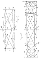
- the girder with two, respectively six spacings is connected to four fixed mountings.
- said fixed mountings are indicated with Lp and Lq and at the righthand side Rp and Rq
- the fixed mountings are schematically depicted with points in, for example, a concrete wall. These points may, however, also form part of, for example, a steel supporting structure.
- the supporting wall or steel structure L and R will have to withstand the net weight and the roof loading transmitted by the girder to the fixed mountings.
- the tension forces, however, for the cables need not be led to the ground through the supports L and R, for instance with the help of yoke- or column cables, but they may be transmitted to separate anchor blocks in the ground.
- the constructions L and R mainly perform a supporting function and may be of much lighter design, because they need to transmit only small bending moments.
- bracings ab up to ef are executed as stiff compression members. All other members consist of flexible cables/ropes.
- FIG. 1 for example a roof-truss-girder is illustrated, in which at its topside the point abp is situated above the fixed mountings Lp and Rp.
- the compression member ab is longer than the distance between the fixed mountings Lp-Lq respectively Rp-Rq, resulting in a situation of the lower end abq of their compression member ab which is less raised above the connecting line Lq-Rq.
- the point abq is positioned higher than said connection line, in order to get an estetic effect when standing under the span, which avoids the impression of a downwardly vaulted span.
- All cables and compression members can be calculated exactly as far as effective length, loading, extension, etc. is concerned. From data made available by the manufacturer of the cables and from possible additional measurements, the characteristics of the cables are known. In contrast to single steel wires, which follow Hooke's law as far as their load-extension characteristic is concerned, flexible cable ropes undergo at low loads a "pre-stretching" before they follow Hooke's law. By taking this into account when fixing the final length of the cable in the girder design under service conditions, the pre-assembly load and the unloaded but stretched manufacturing length may be calculated exactly. Like the compression members, all cables may be manufactured in advance exactly to length and may be laid out on a flat assembly floor according to the designed circuit and in the calculated position.
- the girder After all passing cables have been connected to the ends of the compression members, the girder is ready to be fixed to the fixed mountings by pretensioning all cables ending in said points.
- the pre-assembled girder is not yet stiff and it may be reeled up like a rope ladder and transported in said form. A girder of several dozens of meters thus may be transported in a simple manner and may be off-reeled at the final location of erection.
- the girder has not only become stiff in doing so, but it is able as well to,carry the calculated load. Apart from the applied safetly margins, under all load conditions in all cables at least a little tension will be maintained. Thus the girder remains stiff.
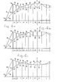
- the girder according to Figures 3 and 4 are basically of the same type as those of Figures 1 and 2, but this time in an embodiment with endless cable circuit.
- the girder is fitted to four fixed mountings. At the lefthand side of the drawing these are the points Lp and Lq and at the righthand side Rp and Rq.
- the same fixed mountings Lp, Lq and Rp, Rq are adopted, but with additional fixed mountings Lm and Rm, which unload the columns L respectively R for the greater part of bending moments and which simplify as well the tensioning of the endless main cables.
- the columns L and R according to Figure 4 may be clamped in the foundation, but they may also be held by non-illustrated guy cables connected to separate anchoring blocks in the ground.
- the stiff compression members which form the strutlike bracings are indicated with a combination of two letters, for instance bc, which means that said compression member follows the limit between the spacings b and c.
- the ends of the compression members all lie on the top chord and therefore they are indicated with the letters of the compression member concerned, with the addition of p and q respectively to indicate its position on the top or bottom level of the vertical mounting.
- the ground level is indicated with m, in which the non-illustrated but necessary anchoring blocks and foundations are situated.
- the manufacture in the works of the endless cables is simplified because the prestretched cable has only to be marked on those places where connecting points, points of intersection or fixing points will be situated in service.
- the endless cables with their marks, factory-made to the correct length can be laid out on the location of erection and fitted to the fixed mountings.
- the compression members may be fitted in advance on the floor or afterwards above the floor, according to circumstances. After all items have been brought to their correct position under a light pre-tension, the girder can be post-tensioned up to the service tension and the clamps at the end of the compression members may also be fastened, which will be discussed below.
- the cables still can be shifted mutually and with regard to the compression members, but after the application of the service tension and the service clamping, this is no longer possible, with the exception of an extra-ordinary overload.
- the column L respectively R will be loaded heavily and it will have to be supported sideways by non-illustrated guy-cables or such, to reduce the bending moments in the columns.
- This complication can be avoided by closing the endless cable circuit between the top chord and bottom chord through an additional third fixed mounting Lm respectively Rm on the ground level, where the tensioners Lt and: Rt may be positioned as well.
- FIG 4 For the sake of clarity, in Figure 4 only some of the elements with which the girder is built are indicated with indices.
- the girder according to Figure 4 is built up with the individual endless cable circuits illustrated in the Figures 4a, 4b and 4c.
- the final construction according to Figure 4 consists of the combination of all which is depicted in the Figures 4a, 4b and 4c, as far as the cables are concerned.
- the illustrated parabolic girder is symmetric about its middle line S-S and that it is therefore sufficient to describe only one half of it (the lefthand half).
- the diagonal bracing cables in the spacings a, b, c and d are not illustrated in the Figures 4, 4a,b,c.
- this connection may be stiffened additionally by applying of non-illustrated "diagonal" bracing cables bcp-dep and bcq-deq, which on first impression do not, but functionally, do form diagonal bracings indeed. On these points the top- and bottom chords cross each other.
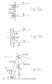
- FIGS. 5a, 5b, 5c show alternative embodiments for the fixed mountings adapted for the endless cable circuits according to the Figures 3 and 4.
- these guides are replaced by levers of adapted shape.
- Each lever is, comparable with the guides, pivotingly mounted with controlled friction on shafts or pins Lp, Lq or Lm in the fixed mountings.
- a cable is pivotingly with controlled friction connected with known cable-end connections which are not illustrated.
- the endless cable circuit is, by doing so, interrupted as construction; but functionally remains umimpaired by the introduction of the levers, avoiding every risk of repeated bending of one or more of the cables. Said cables may therefore be loaded up to the normal limits as accepted for static structures, which are appreciably higher than for dynamic structures in which the cables repeatedly are bent.
- FIGs 6 and 7 show two views of a preferred design of the construction between the ends of the compression members and the cables passing over said ends.
- the compression member ab is illustrated according to Figures 1 or 3, of which the top end abp is depicted in Figures 6 and 7.
- the top end abp is depicted in Figures 6 and 7.
- four cables pass which for example are drawn in Figures 6 and 7 as well.
- a cable clamp 10 is introduced.
- the clamp consists of two halves 11 and 12, which pivot at 13 near to their insert-end 14, connected with each other.
- the end of the cable clamp extending from the compression member ab consists of the clamping jaws 24 and 25, which each have at their outer end a recess to take cable protecting fixing blocks 27.
- the latter have a number of grooves, four in the example, which are adapted to the number and the size of the passing cables to be clamped.
- These fixing blocks 27 can be made of plastic or an other relatively soft material, in which the cables may be clamped firmly, but without damage to them. Under certain conditions of overload one or more cables should be able to move slightly through the fixing blocks without suffering damage.
- both the fixing blocks 27 as the clamping jaws 24 and 25 are rounded by using as little material 29 as possible.
- the connecting point abp forms for one or more of the cables a point of change of direction, as is the case for the cable 3a-4b, it is of advantage to round the ends of the fixing blocks 27 as is illustrated at 30.
- the cables are only slightly clamped by the cable-clamps for which reason the two halves are provided with a wedge-and-slot assembly 19, 20, through which a slot 22 extends to take a conical wedge 21.
- a wedge-and-slot assembly 19 By inserting more or less of the wedge the pre-tension on the cables can be adjusted.
- the girder is brought to the service tension.
- the clamping force on the cables has to be augmented appreciably during said production step, which is achieved by inserting the cable clamps deeper into the compression member over the portion p.
- the cone-shaped end 17 of the female end will wedge itself into the end of the compression member and the latter may be widened elastically and/or plastically by this action, as is indicated with 18 in an exaggerated way.
- the compression member ab is calculated to resist buckling and according to this calculation the profile and thickness of the material is chosen. If the wall thickness should not be sufficient to create sufficient clamping force at 17-18, to create a sufficient clamping force on the cables, then an extra clamping bolt may be applied, which schematically is indicated with the dotted line 23.
Landscapes
- Engineering & Computer Science (AREA)
- Architecture (AREA)
- Civil Engineering (AREA)
- Structural Engineering (AREA)
- Physics & Mathematics (AREA)
- Electromagnetism (AREA)
- Rod-Shaped Construction Members (AREA)
Applications Claiming Priority (4)
| Application Number | Priority Date | Filing Date | Title |
|---|---|---|---|
| NL8100332 | 1981-01-23 | ||
| NL8100332A NL8100332A (nl) | 1981-01-23 | 1981-01-23 | Stijve vakwerkligger in kabelconstructie en werkwijze voor de fabrikage en de toepassing ervan. |
| NL8103524 | 1981-07-27 | ||
| NL8103524A NL8103524A (nl) | 1981-07-27 | 1981-07-27 | Stijve vakwerkligger in kabelconstructie. |
Publications (3)
| Publication Number | Publication Date |
|---|---|
| EP0057038A2 true EP0057038A2 (de) | 1982-08-04 |
| EP0057038A3 EP0057038A3 (en) | 1983-05-25 |
| EP0057038B1 EP0057038B1 (de) | 1986-12-10 |
Family
ID=26645668
Family Applications (1)
| Application Number | Title | Priority Date | Filing Date |
|---|---|---|---|
| EP82200067A Expired EP0057038B1 (de) | 1981-01-23 | 1982-01-19 | Biegesteife Trägerkonstruktion aus biegungsfähigen Kabeltauen |
Country Status (3)
| Country | Link |
|---|---|
| US (1) | US4463526A (de) |
| EP (1) | EP0057038B1 (de) |
| DE (1) | DE3274666D1 (de) |
Cited By (2)
| Publication number | Priority date | Publication date | Assignee | Title |
|---|---|---|---|---|
| CN106958315A (zh) * | 2017-05-17 | 2017-07-18 | 东北林业大学 | 一种大跨度双肢可调控预应力张弦梁 |
| CN108625530A (zh) * | 2018-06-26 | 2018-10-09 | 上海天华建筑设计有限公司 | 张弦梁结构及其施工方法 |
Families Citing this family (3)
| Publication number | Priority date | Publication date | Assignee | Title |
|---|---|---|---|---|
| FR2862995B1 (fr) * | 2003-12-01 | 2006-02-03 | Jean Louis Desbordes | Poutre souple autocontrainte et portiques souples parasismiques |
| CN102493549B (zh) * | 2011-11-28 | 2014-04-30 | 郑毅 | 超跨距网系结构大棚 |
| EA031238B1 (ru) * | 2016-08-29 | 2018-12-28 | Частное проектное унитарное предприятие "Моноракурс" | Пространственная вантовая ферма |
Family Cites Families (18)
| Publication number | Priority date | Publication date | Assignee | Title |
|---|---|---|---|---|
| CA662032A (en) * | 1963-04-30 | R. D. Jawerth Karl | Supporting structures of pre-tensioned cables | |
| US2413019A (en) * | 1942-03-21 | 1946-12-24 | Merl R Wolfard | Stabilizing means for tension elements hanging with sag to sustain loading between supports |
| FR1056325A (fr) * | 1951-02-21 | 1954-02-25 | Système de suspension pour ponts, halles de grande portée, toits et analogues | |
| DE916583C (de) * | 1952-01-16 | 1954-08-12 | Max Gessner Dipl Ing Dipl Ing | Haengewerk fuer weitgespannte Hallen, Daecher u. dgl. |
| US2693195A (en) * | 1952-07-03 | 1954-11-02 | Frieder | Portable shelter |
| FR1285104A (fr) * | 1961-03-29 | 1962-02-16 | Dispositif de liaison entre éléments tels que câble, et ses applications | |
| FR1319962A (fr) * | 1962-04-20 | 1963-03-01 | Procédé pour la construction de bâtiments, avec éléments porteurs constitués par des câbles ou barres d'acier | |
| DE1534743B1 (de) * | 1965-03-09 | 1971-04-29 | Ceskoslovenska Akademie Ved | UEberspanntes Haengewerk zur UEberdachung eines beliebigen Grundrisses |
| FR1446326A (fr) * | 1965-03-31 | 1966-07-22 | Perfectionnements aux structures prétendues, notamment aux structures tridimensionnelles prétendues | |
| NL6504763A (de) * | 1965-04-14 | 1966-10-17 | ||
| NL6801792A (de) * | 1967-02-09 | 1968-08-12 | ||
| SE328391B (de) * | 1968-11-21 | 1970-09-14 | K Jawerth | |
| US3643391A (en) * | 1969-10-03 | 1972-02-22 | Sebastian Mollinger | Roof construction |
| BE760097A (fr) * | 1969-12-12 | 1971-05-17 | Degaine Jacques | Structure de support pour couverture de batiment et batiment utilisant une telle structure |
| SU434163A1 (ru) * | 1972-03-17 | 1974-06-30 | Безраспорная вантовая ферма | |
| SU600267A1 (ru) * | 1972-12-25 | 1978-03-30 | Golikov Sergej P | Каркас здани |
| SU554372A1 (ru) * | 1973-05-03 | 1977-04-15 | Ленинградское Отделение Ордена Трудового Красного Знамени Центрального Научно-Исследовательского И Проектного Института Строительных Металлоконструкций | Вис чее складчатое покрытие |
| SU605917A1 (ru) * | 1976-12-01 | 1978-05-05 | Киевский Зональный Научно-Исследовательский И Проектный Институт Типового И Экспериментального Проектирования Жилых И Общественных Зданий | Вис чее покрытие |
-
1982
- 1982-01-19 DE DE8282200067T patent/DE3274666D1/de not_active Expired
- 1982-01-19 EP EP82200067A patent/EP0057038B1/de not_active Expired
- 1982-01-22 US US06/342,194 patent/US4463526A/en not_active Expired - Fee Related
Cited By (3)
| Publication number | Priority date | Publication date | Assignee | Title |
|---|---|---|---|---|
| CN106958315A (zh) * | 2017-05-17 | 2017-07-18 | 东北林业大学 | 一种大跨度双肢可调控预应力张弦梁 |
| CN108625530A (zh) * | 2018-06-26 | 2018-10-09 | 上海天华建筑设计有限公司 | 张弦梁结构及其施工方法 |
| CN108625530B (zh) * | 2018-06-26 | 2024-01-19 | 上海天华建筑设计有限公司 | 张弦梁结构及其施工方法 |
Also Published As
| Publication number | Publication date |
|---|---|
| DE3274666D1 (en) | 1987-01-22 |
| EP0057038A3 (en) | 1983-05-25 |
| US4463526A (en) | 1984-08-07 |
| EP0057038B1 (de) | 1986-12-10 |
Similar Documents
| Publication | Publication Date | Title |
|---|---|---|
| US4275537A (en) | Tension members | |
| KR910008081B1 (ko) | 트러스 구조물 및 그 건설방법 | |
| CN112982787B (zh) | 一种钢筋混凝土与预应力拉索耦合的大跨度梁 | |
| EP0057038B1 (de) | Biegesteife Trägerkonstruktion aus biegungsfähigen Kabeltauen | |
| KR100540374B1 (ko) | 직선 및 곡선교용 프리캐스트 프리스트레스 콘크리트 빔제작방법을 이용한 교량시공방법 | |
| KR101043239B1 (ko) | 장경간화가 가능한 교량용 분절형 프리스트레스트 콘크리트빔 및 그 제작 방법 | |
| KR100823448B1 (ko) | 면진성이 향상된 프리스트레스트 콘크리트 합성빔 교량의연속화 구조 및 그 공법 | |
| KR102341972B1 (ko) | 강연선 분배장치 및 강연선 분배장치가 적용된 psc 거더 | |
| US11078053B2 (en) | Support of segmented structural design | |
| KR20020057058A (ko) | 에이치 빔을 이용한 교량 보강장치 | |
| EP1235964B1 (de) | Verfahren zur konstruktion einer vorgespannten struktur und eine so hergestellte struktur | |
| CN109639219B (zh) | 一种可拼接式柔性光伏支架 | |
| CN221442188U (zh) | 一种预应力加固结构 | |
| CN219382741U (zh) | 一种漂浮方阵的横向拉索锚固结构及水上光伏系统 | |
| HK1007338A1 (en) | Improvements in cable-stayed bridges, especially in their cables and pillars | |
| KR20000014037A (ko) | 양방향 트러스를 이용한 구조보강 방법 | |
| HK1007338B (en) | Improvements in cable-stayed bridges, especially in their cables and pillars | |
| CN115976984B (zh) | 便于既有独柱墩抗倾覆加固的结构及施工方法 | |
| CN219490722U (zh) | 便于既有独柱墩抗倾覆加固的结构 | |
| KR102391522B1 (ko) | 이중쐐기 정착구와 편심조절 새들을 구비한 외부강선 정착장치 및 이를 이용한 외부강선 보강 방법 | |
| CN118669273A (zh) | 风电塔架的体外预应力束的布置结构、风电塔架及施工方法 | |
| KR200278091Y1 (ko) | 사장 외부케이블을 이용한 손상된 교량에서의 보수보강장치 | |
| CN115030317A (zh) | 一种无需预应力构件的大跨度桁架顶棚 | |
| CN115162534A (zh) | 一种大跨度异形桁架顶棚施工方法 | |
| KR100442969B1 (ko) | 사장 외부케이블을 이용한 손상된 교량에서의 보수보강방법 및 그 장치 |
Legal Events
| Date | Code | Title | Description |
|---|---|---|---|
| PUAI | Public reference made under article 153(3) epc to a published international application that has entered the european phase |
Free format text: ORIGINAL CODE: 0009012 |
|
| AK | Designated contracting states |
Designated state(s): CH DE FR NL |
|
| PUAL | Search report despatched |
Free format text: ORIGINAL CODE: 0009013 |
|
| AK | Designated contracting states |
Designated state(s): CH DE FR LI NL |
|
| 17P | Request for examination filed |
Effective date: 19831109 |
|
| RAP1 | Party data changed (applicant data changed or rights of an application transferred) |
Owner name: LAGENDIJK, JOHANNES |
|
| GRAA | (expected) grant |
Free format text: ORIGINAL CODE: 0009210 |
|
| AK | Designated contracting states |
Kind code of ref document: B1 Designated state(s): CH DE FR LI NL |
|
| REF | Corresponds to: |
Ref document number: 3274666 Country of ref document: DE Date of ref document: 19870122 |
|
| ET | Fr: translation filed | ||
| PLBE | No opposition filed within time limit |
Free format text: ORIGINAL CODE: 0009261 |
|
| STAA | Information on the status of an ep patent application or granted ep patent |
Free format text: STATUS: NO OPPOSITION FILED WITHIN TIME LIMIT |
|
| 26N | No opposition filed | ||
| REG | Reference to a national code |
Ref country code: CH Ref legal event code: PUE Owner name: JOHANNES LAGENDIJK TRANSFER- BEHEERSMAATSCHAPPIJ P |
|
| REG | Reference to a national code |
Ref country code: FR Ref legal event code: TP |
|
| REG | Reference to a national code |
Ref country code: FR Ref legal event code: TP |
|
| PGFP | Annual fee paid to national office [announced via postgrant information from national office to epo] |
Ref country code: FR Payment date: 19990201 Year of fee payment: 18 |
|
| PGFP | Annual fee paid to national office [announced via postgrant information from national office to epo] |
Ref country code: DE Payment date: 19990205 Year of fee payment: 18 |
|
| PGFP | Annual fee paid to national office [announced via postgrant information from national office to epo] |
Ref country code: CH Payment date: 19990226 Year of fee payment: 18 |
|
| PG25 | Lapsed in a contracting state [announced via postgrant information from national office to epo] |
Ref country code: LI Free format text: LAPSE BECAUSE OF NON-PAYMENT OF DUE FEES Effective date: 20000131 Ref country code: CH Free format text: LAPSE BECAUSE OF NON-PAYMENT OF DUE FEES Effective date: 20000131 |
|
| PGFP | Annual fee paid to national office [announced via postgrant information from national office to epo] |
Ref country code: NL Payment date: 20000131 Year of fee payment: 19 |
|
| REG | Reference to a national code |
Ref country code: CH Ref legal event code: PL |
|
| PG25 | Lapsed in a contracting state [announced via postgrant information from national office to epo] |
Ref country code: FR Free format text: LAPSE BECAUSE OF NON-PAYMENT OF DUE FEES Effective date: 20000929 |
|
| PG25 | Lapsed in a contracting state [announced via postgrant information from national office to epo] |
Ref country code: DE Free format text: LAPSE BECAUSE OF NON-PAYMENT OF DUE FEES Effective date: 20001101 |
|
| REG | Reference to a national code |
Ref country code: FR Ref legal event code: ST |
|
| NLS | Nl: assignments of ep-patents |
Owner name: BEHEERSMAATSCHAPPIJ P. BUITENDIJK B.V. |
|
| PG25 | Lapsed in a contracting state [announced via postgrant information from national office to epo] |
Ref country code: NL Free format text: LAPSE BECAUSE OF NON-PAYMENT OF DUE FEES Effective date: 20010801 |
|
| NLV4 | Nl: lapsed or anulled due to non-payment of the annual fee |
Effective date: 20010801 |