EP0057032B1 - Procédé et dispositif d'aide à la navigation aérienne ou maritime - Google Patents
Procédé et dispositif d'aide à la navigation aérienne ou maritime Download PDFInfo
- Publication number
- EP0057032B1 EP0057032B1 EP82200045A EP82200045A EP0057032B1 EP 0057032 B1 EP0057032 B1 EP 0057032B1 EP 82200045 A EP82200045 A EP 82200045A EP 82200045 A EP82200045 A EP 82200045A EP 0057032 B1 EP0057032 B1 EP 0057032B1
- Authority
- EP
- European Patent Office
- Prior art keywords
- board
- navigation
- conventional coordinates
- coordinates
- map
- Prior art date
- Legal status (The legal status is an assumption and is not a legal conclusion. Google has not performed a legal analysis and makes no representation as to the accuracy of the status listed.)
- Expired
Links
- 238000000034 method Methods 0.000 title claims abstract description 34
- 230000015654 memory Effects 0.000 claims description 11
- 238000005259 measurement Methods 0.000 claims description 8
- 230000002093 peripheral effect Effects 0.000 claims description 5
- 238000013459 approach Methods 0.000 claims description 3
- 238000013519 translation Methods 0.000 claims description 2
- 238000012800 visualization Methods 0.000 claims description 2
- 230000005611 electricity Effects 0.000 claims 1
- 238000013479 data entry Methods 0.000 description 6
- 230000006870 function Effects 0.000 description 6
- 235000021183 entrée Nutrition 0.000 description 3
- 238000012550 audit Methods 0.000 description 2
- 238000010586 diagram Methods 0.000 description 2
- 238000005286 illumination Methods 0.000 description 2
- WWYNJERNGUHSAO-XUDSTZEESA-N (+)-Norgestrel Chemical compound O=C1CC[C@@H]2[C@H]3CC[C@](CC)([C@](CC4)(O)C#C)[C@@H]4[C@@H]3CCC2=C1 WWYNJERNGUHSAO-XUDSTZEESA-N 0.000 description 1
- 241000861223 Issus Species 0.000 description 1
- 230000000712 assembly Effects 0.000 description 1
- 238000000429 assembly Methods 0.000 description 1
- 230000005540 biological transmission Effects 0.000 description 1
- 230000015556 catabolic process Effects 0.000 description 1
- 238000005520 cutting process Methods 0.000 description 1
- 238000011161 development Methods 0.000 description 1
- 230000010006 flight Effects 0.000 description 1
- 239000000446 fuel Substances 0.000 description 1
- 238000003780 insertion Methods 0.000 description 1
- 230000037431 insertion Effects 0.000 description 1
- 230000033001 locomotion Effects 0.000 description 1
- 239000003550 marker Substances 0.000 description 1
- 230000003287 optical effect Effects 0.000 description 1
- 230000000737 periodic effect Effects 0.000 description 1
- 238000012546 transfer Methods 0.000 description 1
- 230000017105 transposition Effects 0.000 description 1
Images
Classifications
-
- G—PHYSICS
- G01—MEASURING; TESTING
- G01C—MEASURING DISTANCES, LEVELS OR BEARINGS; SURVEYING; NAVIGATION; GYROSCOPIC INSTRUMENTS; PHOTOGRAMMETRY OR VIDEOGRAMMETRY
- G01C21/00—Navigation; Navigational instruments not provided for in groups G01C1/00 - G01C19/00
- G01C21/20—Instruments for performing navigational calculations
-
- G—PHYSICS
- G01—MEASURING; TESTING
- G01S—RADIO DIRECTION-FINDING; RADIO NAVIGATION; DETERMINING DISTANCE OR VELOCITY BY USE OF RADIO WAVES; LOCATING OR PRESENCE-DETECTING BY USE OF THE REFLECTION OR RERADIATION OF RADIO WAVES; ANALOGOUS ARRANGEMENTS USING OTHER WAVES
- G01S2205/00—Position-fixing by co-ordinating two or more direction or position line determinations; Position-fixing by co-ordinating two or more distance determinations
- G01S2205/01—Position-fixing by co-ordinating two or more direction or position line determinations; Position-fixing by co-ordinating two or more distance determinations specially adapted for specific applications
- G01S2205/03—Airborne
-
- G—PHYSICS
- G01—MEASURING; TESTING
- G01S—RADIO DIRECTION-FINDING; RADIO NAVIGATION; DETERMINING DISTANCE OR VELOCITY BY USE OF RADIO WAVES; LOCATING OR PRESENCE-DETECTING BY USE OF THE REFLECTION OR RERADIATION OF RADIO WAVES; ANALOGOUS ARRANGEMENTS USING OTHER WAVES
- G01S2205/00—Position-fixing by co-ordinating two or more direction or position line determinations; Position-fixing by co-ordinating two or more distance determinations
- G01S2205/01—Position-fixing by co-ordinating two or more direction or position line determinations; Position-fixing by co-ordinating two or more distance determinations specially adapted for specific applications
- G01S2205/04—Nautical
-
- G—PHYSICS
- G01—MEASURING; TESTING
- G01S—RADIO DIRECTION-FINDING; RADIO NAVIGATION; DETERMINING DISTANCE OR VELOCITY BY USE OF RADIO WAVES; LOCATING OR PRESENCE-DETECTING BY USE OF THE REFLECTION OR RERADIATION OF RADIO WAVES; ANALOGOUS ARRANGEMENTS USING OTHER WAVES
- G01S5/00—Position-fixing by co-ordinating two or more direction or position line determinations; Position-fixing by co-ordinating two or more distance determinations
- G01S5/02—Position-fixing by co-ordinating two or more direction or position line determinations; Position-fixing by co-ordinating two or more distance determinations using radio waves
Definitions
- the invention relates to a method and a device for air or maritime navigation, making it possible to prepare and deliver information for aid to navigation, such as in particular the position of an aircraft or a ship, the heading angle. to be followed to reach a place of destination, distance separating the aircraft or the ship from the place of destination. It relates to a method and a device, using bearings operated in relation to tracking stations by means of appropriate navigation instruments, for example in the aeronautical field, magnetic bearing in relation to a radio station ("VOR" station; station "NDB”), in the maritime domain, bearings operated by direction-finding, ...
- VOR radio station
- NDB radio station
- »VOR« (»VHF Omni Range «) or »NDB-ADF « (»Non Directional Beacon-Automatic Direction Finder «) systems provide either a magnetic bearing relative to the station »VOR « or a station bearing »NDB "Relative to the axis of the aircraft.
- Two measurements made on two stations make it possible to determine the position on a map by making geometric traces requiring the use of a protractor, a ruler and a map support board.
- the »DME « (»Distance Measuring Equipment «) system provides the oblique distance separating the aircraft (at altitude) from the »DME « station on the ground. Combined with a »VOR « it allows positioning in the same conditions as before.
- the »CLC-RNAV « (»Area Navigation Calculator «) is a computer associated with the on-board »VOR « and »DME « devices; this system makes it possible to place a fictitious "VOR-DME” at any point located within radio range "VHF” (therefore optical) of a real “VOR-DME” whose presence is essential.
- VHF radio range
- VOR-DME real "VOR-DME”
- the imprecision with which the position of the aircraft is known can become a determining factor in increasing the risk in the event of any breakdown or annoyance, the pilot having to use approximations to reach the nearest aerodrome.
- G-NAV Great Britain
- GB 868 398 describes a navigation computer which is associated with a pointer indicator system making it possible to display the results calculated by the latter.
- This device has the disadvantage already mentioned of involving the use of the rule and the protractor, which is extremely inconvenient in a confined cabin. In addition, if he can give the course to follow and the distance remaining to be traveled, he is totally incapable of providing the position of the aircraft.
- the present invention proposes to indicate a satisfactory solution allowing a pilot to know his position in a practical, fast and precise manner, by means of an inexpensive device and of simple use.
- Another objective is to allow the pilot to determine, under the same conditions, the course to follow in order to reach a destination.
- Another object of the invention is also to provide the pilot, under the same conditions of precision, the distance which separates him from a place of destination, without having to use in the aeronautical field the stations "DME", so as to be totally exempt from the specific faults of this system (and in particular the risks of saturation).
- Another objective is to also provide the pilot with other navigation aid information, such as for example the direction and speed of the real wind.
- Another objective is to indicate a method and a device making it possible to develop and deliver this information, by means of the charts usually used in the field concerned, current aeronautical charts for air navigation or maritime charts for maritime navigation.
- Another objective is to indicate a method and a device using the bearings operated by means of appropriate instruments with respect to any tracking stations, for example any radionavigation station located in the area covered by the map used ( or if necessary located near this area).
- the signal representative of the heading angle (Rm) can be generated directly using the data (X 1 , Y 1 ; X 2 , Y 2 x, y; R 1 , R 2 ). It can also be generated indirectly from this data, using the result of the position calculations (X, Y) and some of the above data (x, y); this latter generation mode will be preferred in practice since the logical operations to be carried out on the corresponding signals are notably simplified in this case.
- an electrical signal representative of the distance (D) separating the aircraft is also generated from the above-mentioned signals (used directly or, preferably, in the form of results already obtained). the ship from the place of destination and this distance is displayed.
- the method of the invention uses conventional maps, the scale of which is indifferent. Indeed, it consists of superimposing on the map a conventional coordinate system from which are operated both the reading of the coordinates of a station and the location of a position; it suffices, for a given measurement, that the card remains the same and remains in an unchanged position relative to the plate, the type of card and its scale can be arbitrary.
- the pilot can in particular use conventional maps which he himself will have previously cut out to facilitate their positioning on the navigation platform; to avoid this cutting operation, a set of pre-cut cards in the shape of the board and covering a determined territory will preferably be provided, these cards being of the type usually used (projection and scale) so that the pilot can easily follow its course as it progresses.
- the tracking stations with their characteristics are shown. Note that, if necessary, each card can be edited with reference lines corresponding to the reference system linked to the plate so as to further facilitate readings or markings, once the card positioned on the plate.
- the location on the map is determined without any geometric tracing by simple readings and markings: reading of the conventional coordinates of the two chosen marker stations (either by reading an abscissa and an ordinate by means of the system board reference, either by direct reading of numbers written on the card next to the station for cards that are part of a specially edited deck), location of the position on the map using the board reference system from calculated conventional coordinates.
- reading of the conventional coordinates of the two chosen marker stations either by reading an abscissa and an ordinate by means of the system board reference, either by direct reading of numbers written on the card next to the station for cards that are part of a specially edited deck
- location of the position on the map using the board reference system from calculated conventional coordinates.
- the pilot can use any station for any measurement and the failure of one or more of them does not neutralize the system.
- the method is further simplified since it is no longer necessary to read the coordinates thereof.
- the stations used will preferably be "VOR” or "NDB” radio-navigation stations which are widely used and do not present any risk of saturation.
- all the operations of the method are carried out using conventional coordinates which are characteristic of the system according to the invention and defined by the reference system linked to the plate.
- This reference system preferably constituted by two graduated perpendicular axes, can be chosen so that each point of the plate is represented by two conventional coordinates of three or four digits each depending on the plate size; four digits per coordinate is a maximum which will not be exceeded in practice and which provides very largely sufficient accuracy of representation.
- the number of digits to be read and dialed on a keyboard is limited in the case of the invention and the user constantly has in front of him (at the level of the platform) the reference system with respect to which he is working.
- the data entry system comprises a keyboard arranged at the edge of the navigation tray and provided with a plurality of keys, which are marked, on the one hand, with identification signs of nature data to be entered (station 1: Xi Y 1 R 1 , station 2: X 2 Y 2 R 2 , destination: xy), on the other hand, numerical indications for the composition of the various digits of each data.
- the function keys corresponding to the nature of the data and the numeric keys can be separated arranged in different locations of the keyboard or common ladles assulating the two sheets.
- the display means are preferably composed of several segment displays and means of indicating the type of information displayed (X, Y, Rm, D ).
- the segment displays are few in number, of the order of 5 to 6, and have a function of universal display of information of all kinds; the means for indicating the type of information displayed are then constituted by light means such as several light-emitting diodes, which make it possible to display the type of information displayed.
- the computing means of the device advantageously comprise a microcomputer provided with a computing unit, a read only memory for storing a calculation program, a random access memory for storing renewable data, and interfaces. interposed between the calculation unit and the memories or the display means.
- the device of the invention may include its own electrical supply means and be entirely autonomous and independent of the aircraft (or of the ship). It can also be connected by an appropriate connection to the aircraft batteries.
- the price of such a device is very moderate and is, for example, more than 30 times lower than "CLC-RNAV" equipment, although it does not have the disadvantages and provides more services than this.
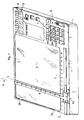
- the navigation aid device shown by way of example in the figures consists of a casing 1 of small thickness and of generally rectangular shape, delimiting a flat plate 2, rectangular or square, called the navigation plate, which extends over most of the surface of the housing.
- This navigation tray 2 is situated slightly set back with respect to a peripheral border 3 slightly projecting in order to delimit a housing in which a card is capable of being positioned, the edges of the latter coming into contact with the border 3 of so as to give it a precise position that is invariable relative to the plate 2.
- the peripheral border 3 is interrupted by two notches 3a, 3b for the passage of card identification tabs.
- the box 1 On one side (4) of the plate 2, the box 1 forms a support for a data entry system and for display means, which will be described later; in addition, it makes it possible to house calculation means that the device comprises as well as means for supplying power to the various electronic assemblies.
- the navigation plate 2 is provided with a calibration system, consisting of a system of two axes (X, Y) perpendicular to each other, each axis being parallel to an edge of the plate and graduated from an origin.
- One of the axes (X) is carried by an edge 5 of the plate and is graduated from an origin located near the left end of this edge.
- the other axis (Y) is carried by a movable cursor 6 which extends perpendicular to the edge 5 over the entire height of the plate; this cursor is graduated from an origin located at its lower part in the vicinity of edge 5.
- the graduations of the X and Y axes are conventional and can be any; however, use is preferably made of graduations having the same scale on the two axes and which represent the units of distance most commonly used in the field concerned, on the scale of the most commonly used maps.
- Such a tray size constitutes an excellent compromise which, at the same time, ensures great ease of use and handling of the device (coming from a relatively small footprint) and allows each card to cover a satisfactory area of territory ( about 150 NM out of 100 NM) avoiding too frequent card changes.
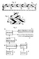
- the cursor 6 is associated with means for guiding in translation, adapted to allow it to be moved parallel to the edge 5 over the entire length thereof; in the example, these means consist of a slide 7 provided along the edge 5, with which the foot 6a of the slider cooperates, slide format. Small elastic blades 8 allow movement of the cursor 6 without risk of jamming, while preserving the perpendicularity thereof relative to the edge 5.
- the device comprises an electronic assembly, the block diagram of which is provided in FIG. 4.
- This essentially consists of a data entry system 9, a calculation unit 10 constituted in the example by a microprocessor, a read only memory 11 ("ROM”) for storing a calculation program, a random access memory 12 ("RAM”) for storing the renewable data coming from the input system 9, display means 13 and 14 of the results and interfaces 15 and 16 interposed between the calculation unit 10 and the memories 11 and 12 or the display means 13 and 14; conventionally, these interfaces are in the example constituted by multiplexers and decoders.
- the data entry system 9 is adapted to make it possible to generate electrical signals representative of the data which are composed on a keyboard which this system includes.
- This keyboard is provided with a plurality of keys carried by the edge 4 of the housing.
- numeric keys allowing to compose the digits of a data (abscissa, ordered, bearing) by assigning them if necessary a sign (whose usefulness will be seen further on); some of these keys also act as function keys and allow you to assign a code characteristic of the nature of the data.
- function keys are essentially eight in number: conventional abscissa x and conventional ordinate y of the place of destination to be reached, abscissa Xi, ordinate Yi of the first station, bearing Ri measured with respect to this first station, abscissa X 2 , ordinate Y 2 and bearing R 2 of the second station. As shown in Figure 1, these function keys are marked with appropriate identification signs.
- the keyboard conventionally includes various keys, such as a control key. a calculation, erase key, memory (or storage) key, as well as an electrical power switch, and a NAVIGATION / PERFORMANCE selector which allows either to activate the navigation program or to have the means of calculation in a state to carry out other calculations from specific data or certain results of navigation calculations (calculation of airplane speed, ground speed, real time necessary to reach a place destination, drift etc ).
- a control key such as a control key.
- a calculation, erase key, memory (or storage) key such as well as an electrical power switch, and a NAVIGATION / PERFORMANCE selector which allows either to activate the navigation program or to have the means of calculation in a state to carry out other calculations from specific data or certain results of navigation calculations (calculation of airplane speed, ground speed, real time necessary to reach a place destination, drift etc ).
- the display means carried by the edge 4 of the housing include, in the example, five displays 13 with seven segments, with a view to displaying the different digits of a result information and a set 14 of several diodes luminescent, each corresponding to the nature of information-result.
- each diode which lights up when the result appearing on the displays 13 corresponds to this
- an indication of the type of information concerned in the example: Calc. (data insertion), X (calculated conventional abscissa of the position), Y (position ordinate), Rm (heading from the place of destination), D (distance from the place of destination, v (wind speed), r ( wind direction) and various aforementioned additional information that can be calculated by the calculation means (Vp: airplane speed, V s : ground speed, T r : real time to reach a destination, d: drift).
- the navigation program which is stored in the ROM 11 is adapted to manage the execution of the various navigation calculations to be performed, essentially: calculation of the conventional coordinates X and Y from the coordinates and bearings of the two stations X 1 , Yi, Ri, X 2 , Y 2 , R 2 , calculation of the heading Rm from the calculated coordinates X, Y and the coordinates x and y of the place of destination, finally calculation of the distance D from the calculated coordinates X, Y and x and y coordinates.
- the coefficient K is a coefficient taking into account the scale of the maps used, the calibration of the board 2 and the unit in which the pilot wishes the distance to be expressed.
- this coefficient is equal to 1.0799.
- the device of the invention is preferably equipped with a set of specially edited plastic cards, which cover a given territory divided into regions each corresponding to a card.
- French territory can be represented by approximately 20 to 25 maps per 1 / 1,000,000th, printed on both sides on plasticized paper supports (representing a set of 10 to 15 supports that can be stored under the tray 2 to inside the housing).
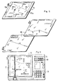
- Each map such as map 17 shown diagrammatically in FIG. 5, includes an identification tab 17a bearing indications, recto-verso, adapted to facilitate the choice of the map which corresponds to the navigation region.
- the dimensions of the maps correspond to those of the navigation board 2.
- the card For each station, the card bears the indication of its transmission frequency and preferably, the indication written in numbers of its conventional coordinates which allows direct reading without using the cursor 6. Similarly, the Conventional coordinates of each aerodrome (or main aerodromes in the region) can also be written on the map for the same purpose.
- the map may have a peripheral margin such as 17b, in which the radio navigation stations "VOR” or “NDB” near the region covered by the map are noted, with their frequency and their conventional coordinates. It is thus possible to take bearings in relation to stations located outside the map, which can, in certain cases, avoid changes in cards; the abscissa or the ordinate of such stations can be negative and the data is assigned the corresponding sign by means of the appropriate key on the keyboard.
- the deck of cards can be supplemented by cards such as 18 to and from the aerodromes.
- the arrival card is printed on the front and the approach card on the back of the same support.
- the scale of one can be 1 / 50,000 and that of the other 1 / 10,000.
- Each of these charts carries the conventional coordinates of the aerodrome and the recommended trajectory of arrival or approach to the aerodrome (with the various flight characteristics recommended).
- these cards also bear the indication of two stations "VOR” or "NDB", within radio range of the aerodrome, with their characteristics.
- Figure 6 a schematic plan view of the device, to illustrate the method according to the invention.
- This consists of selecting the card 17 corresponding to the region overflown and positioning it on the plate 2 in the housing delimited by the projecting edges of said plate.
- reading these simply involves sliding the cursor 6 parallel to the edge 5 in order to cause it to pass through the station (or more generally by the point concerned) and to read one of the coordinates on the cursor at the level of the point concerned (ordered) and the other on edge 5 at the foot of the cursor.
- the coordinates (X i , Y,) (X 2 , Y 2 ) of the two stations are inserted into the storage memory 12, by dialing them on the keyboard 9 which translates them in the form of coded electrical signals.
- the pilot then conventionally measures the bearings (R 1 , R 2 ) of the two stations “VOR” or “NDB” by means of the radio-navigation instruments “VOR” or “ADF” of the airplane and inserts these bearings in memory 12.
- the pilot locates on the map the position of the aircraft by means of the coordinates read on the displays. He just has to slide the cursor 6 in order to bring his foot onto the graduation corresponding to the abscissa read X and to locate the point corresponding to the position, along the cursor opposite the graduation corresponding to the ordinate read Y.
- the pilot After having made a first position (X, Y) and bearing (Rm) measurement, the pilot chooses on the calculated bearing line Rm, an intermediate destination (x ;, y;) corresponding to a known journey time t to from the initial position (X, Y) (for example 5 minutes).
- a program corresponding to these calculations is stored in memory 11 in order to ensure a direct display of this information on the displays 13 (k being a coefficient depending on the units).
Landscapes
- Engineering & Computer Science (AREA)
- Radar, Positioning & Navigation (AREA)
- Remote Sensing (AREA)
- Automation & Control Theory (AREA)
- Physics & Mathematics (AREA)
- General Physics & Mathematics (AREA)
- Navigation (AREA)
Applications Claiming Priority (2)
| Application Number | Priority Date | Filing Date | Title |
|---|---|---|---|
| FR8101346 | 1981-01-22 | ||
| FR8101346A FR2498317A1 (fr) | 1981-01-22 | 1981-01-22 | Procede et dispositif d'aide a la navigation aerienne ou maritime |
Publications (3)
| Publication Number | Publication Date |
|---|---|
| EP0057032A2 EP0057032A2 (fr) | 1982-08-04 |
| EP0057032A3 EP0057032A3 (en) | 1982-08-18 |
| EP0057032B1 true EP0057032B1 (fr) | 1985-09-11 |
Family
ID=9254480
Family Applications (1)
| Application Number | Title | Priority Date | Filing Date |
|---|---|---|---|
| EP82200045A Expired EP0057032B1 (fr) | 1981-01-22 | 1982-01-15 | Procédé et dispositif d'aide à la navigation aérienne ou maritime |
Country Status (3)
| Country | Link |
|---|---|
| EP (1) | EP0057032B1 (enExample) |
| DE (1) | DE3266077D1 (enExample) |
| FR (1) | FR2498317A1 (enExample) |
Families Citing this family (5)
| Publication number | Priority date | Publication date | Assignee | Title |
|---|---|---|---|---|
| DE3218317A1 (de) * | 1982-05-14 | 1983-11-24 | Siemens AG, 1000 Berlin und 8000 München | Peilzentralen-einrichtung |
| EP0103847B1 (de) * | 1982-09-16 | 1988-12-07 | TELDIX GmbH | Navigationshilfe für ein Fahrzeug |
| EP0126915B1 (de) * | 1983-05-27 | 1988-01-13 | VDO Adolf Schindling AG | Informationseingabe |
| FR2664379B2 (fr) * | 1988-10-12 | 1994-09-16 | Allouard Guy | Appareil electronique d'aide a l'etablissement de la navigation aerienne pour les aeronefs legers. |
| EP3271686B1 (en) * | 2015-03-19 | 2020-12-23 | Vricon Systems Aktiebolag | Position determining unit and a method for determining a position of a land or sea based object |
Family Cites Families (7)
| Publication number | Priority date | Publication date | Assignee | Title |
|---|---|---|---|---|
| NL80099C (enExample) * | 1946-01-23 | |||
| US2710962A (en) * | 1953-11-23 | 1955-06-14 | Collins Radio Co | Punch card controlled aircraft navigation computer |
| GB868398A (en) * | 1958-04-17 | 1961-05-17 | Kelvin & Hughes Ltd | Improvements in and relating to computing apparatus |
| DE1548416C3 (de) * | 1966-11-28 | 1974-01-31 | Decca Ltd., London | Anordnung zur Positionsanzeige für ein bewegliches Fahrzeug, insbesondere Flugzeug |
| US3882501A (en) * | 1974-02-11 | 1975-05-06 | Northrop Corp | System for determining speed and heading of airborne equipment with rectilinear coordinate positions |
| FR2291479A1 (fr) * | 1974-11-18 | 1976-06-11 | Sfena | Procede et appareil d'indication de position geographique d'un vehicule pilote |
| US4086632A (en) * | 1976-09-27 | 1978-04-25 | The Boeing Company | Area navigation system including a map display unit for establishing and modifying navigation routes |
-
1981
- 1981-01-22 FR FR8101346A patent/FR2498317A1/fr active Granted
-
1982
- 1982-01-15 DE DE8282200045T patent/DE3266077D1/de not_active Expired
- 1982-01-15 EP EP82200045A patent/EP0057032B1/fr not_active Expired
Also Published As
| Publication number | Publication date |
|---|---|
| EP0057032A2 (fr) | 1982-08-04 |
| EP0057032A3 (en) | 1982-08-18 |
| FR2498317B1 (enExample) | 1984-03-16 |
| FR2498317A1 (fr) | 1982-07-23 |
| DE3266077D1 (en) | 1985-10-17 |
Similar Documents
| Publication | Publication Date | Title |
|---|---|---|
| FR2694392A1 (fr) | Procédé d'assistance à la navigation. | |
| EP2792998B1 (en) | Systems and methods for generating a navigation chart | |
| McNamara | GPS for Dummies | |
| FR2723227A1 (fr) | Procede de controle de la navigation d'un aeronef, et planche de vol interactive pour la mise en oeuvre dudit procede | |
| EP0357515A1 (fr) | Système de navigation terrestre visualisant en temps réel la position d'un véhicule | |
| FR2920242A1 (fr) | Procede et dispositif d'annotation de fonds cartographiques electroniques | |
| Adams | Hydrographic manual | |
| EP0057032B1 (fr) | Procédé et dispositif d'aide à la navigation aérienne ou maritime | |
| Nicolai | The premedieval origin of portolan charts: New geodetic evidence | |
| OA12461A (fr) | Système de mesure et de localisation utilisant lesbases trois et neuf et applications correspondant es. | |
| US20120110865A1 (en) | Chart specific navigation plotter and method for inexpensive production thereof | |
| US3724079A (en) | Navigational chart display device | |
| Brcko et al. | Investigating the Human Factor in Maritime Accidents: A Focus on Compass-Related Incidents | |
| Knox-Johnston | Practical Assessment of the Accuracy of the Astrolabe | |
| FR2623911A1 (fr) | Systeme de controle ou d'aide a la navigation maritime ou la circulation | |
| EP2630445B1 (fr) | Systeme et procede de cartographie avec representation de manoeuvres | |
| Lobo-Guerrero | On the epistemology of maps and mapping: De la Cosa, Mercator and the making of spatial imaginaries | |
| EP0331544A1 (fr) | Dispositif permettant la lecture directe, sur une carte, du cap à suivre par un véhicule aérien ou nautique | |
| US3350007A (en) | Navigation slide rule | |
| US4442605A (en) | Dead reckoning navigation instrument | |
| FR2920580A1 (fr) | Procede de simplification de l'affichage d'elements stationnaires d'une base de donnees embarquee | |
| US2073352A (en) | Adjustable direction-finder chart | |
| Gynther et al. | Radio Aids to Navigation Requirements: The 1988 Simulator Experiment | |
| FR2547410A1 (fr) | Regle de navigation aerienne | |
| Featherstone | Outdoor guide to using your GPS |
Legal Events
| Date | Code | Title | Description |
|---|---|---|---|
| PUAI | Public reference made under article 153(3) epc to a published international application that has entered the european phase |
Free format text: ORIGINAL CODE: 0009012 |
|
| PUAL | Search report despatched |
Free format text: ORIGINAL CODE: 0009013 |
|
| AK | Designated contracting states |
Designated state(s): BE CH DE GB IT NL SE |
|
| AK | Designated contracting states |
Designated state(s): BE CH DE GB IT NL SE |
|
| 17P | Request for examination filed |
Effective date: 19820923 |
|
| GRAA | (expected) grant |
Free format text: ORIGINAL CODE: 0009210 |
|
| AK | Designated contracting states |
Designated state(s): BE CH DE GB IT LI NL SE |
|
| PG25 | Lapsed in a contracting state [announced via postgrant information from national office to epo] |
Ref country code: NL Effective date: 19850911 Ref country code: IT Free format text: LAPSE BECAUSE OF FAILURE TO SUBMIT A TRANSLATION OF THE DESCRIPTION OR TO PAY THE FEE WITHIN THE PRESCRIBED TIME-LIMIT;WARNING: LAPSES OF ITALIAN PATENTS WITH EFFECTIVE DATE BEFORE 2007 MAY HAVE OCCURRED AT ANY TIME BEFORE 2007. THE CORRECT EFFECTIVE DATE MAY BE DIFFERENT FROM THE ONE RECORDED. Effective date: 19850911 |
|
| PG25 | Lapsed in a contracting state [announced via postgrant information from national office to epo] |
Ref country code: SE Effective date: 19850930 |
|
| REF | Corresponds to: |
Ref document number: 3266077 Country of ref document: DE Date of ref document: 19851017 |
|
| PG25 | Lapsed in a contracting state [announced via postgrant information from national office to epo] |
Ref country code: LI Effective date: 19860131 Ref country code: CH Effective date: 19860131 Ref country code: BE Effective date: 19860131 |
|
| NLV1 | Nl: lapsed or annulled due to failure to fulfill the requirements of art. 29p and 29m of the patents act | ||
| PLBE | No opposition filed within time limit |
Free format text: ORIGINAL CODE: 0009261 |
|
| STAA | Information on the status of an ep patent application or granted ep patent |
Free format text: STATUS: NO OPPOSITION FILED WITHIN TIME LIMIT |
|
| BERE | Be: lapsed |
Owner name: MESSUD MICHEL Effective date: 19860131 |
|
| 26N | No opposition filed | ||
| REG | Reference to a national code |
Ref country code: CH Ref legal event code: PL |
|
| GBPC | Gb: european patent ceased through non-payment of renewal fee | ||
| PG25 | Lapsed in a contracting state [announced via postgrant information from national office to epo] |
Ref country code: DE Effective date: 19881001 |
|
| PG25 | Lapsed in a contracting state [announced via postgrant information from national office to epo] |
Ref country code: GB Free format text: LAPSE BECAUSE OF NON-PAYMENT OF DUE FEES Effective date: 19881121 |