EP0057032B1 - Method and means for assisting aerial or maritime navigation - Google Patents
Method and means for assisting aerial or maritime navigation Download PDFInfo
- Publication number
- EP0057032B1 EP0057032B1 EP82200045A EP82200045A EP0057032B1 EP 0057032 B1 EP0057032 B1 EP 0057032B1 EP 82200045 A EP82200045 A EP 82200045A EP 82200045 A EP82200045 A EP 82200045A EP 0057032 B1 EP0057032 B1 EP 0057032B1
- Authority
- EP
- European Patent Office
- Prior art keywords
- board
- navigation
- conventional coordinates
- coordinates
- map
- Prior art date
- Legal status (The legal status is an assumption and is not a legal conclusion. Google has not performed a legal analysis and makes no representation as to the accuracy of the status listed.)
- Expired
Links
Images
Classifications
-
- G—PHYSICS
- G01—MEASURING; TESTING
- G01C—MEASURING DISTANCES, LEVELS OR BEARINGS; SURVEYING; NAVIGATION; GYROSCOPIC INSTRUMENTS; PHOTOGRAMMETRY OR VIDEOGRAMMETRY
- G01C21/00—Navigation; Navigational instruments not provided for in groups G01C1/00 - G01C19/00
- G01C21/20—Instruments for performing navigational calculations
-
- G—PHYSICS
- G01—MEASURING; TESTING
- G01S—RADIO DIRECTION-FINDING; RADIO NAVIGATION; DETERMINING DISTANCE OR VELOCITY BY USE OF RADIO WAVES; LOCATING OR PRESENCE-DETECTING BY USE OF THE REFLECTION OR RERADIATION OF RADIO WAVES; ANALOGOUS ARRANGEMENTS USING OTHER WAVES
- G01S2205/00—Position-fixing by co-ordinating two or more direction or position line determinations; Position-fixing by co-ordinating two or more distance determinations
- G01S2205/01—Position-fixing by co-ordinating two or more direction or position line determinations; Position-fixing by co-ordinating two or more distance determinations specially adapted for specific applications
- G01S2205/03—Airborne
-
- G—PHYSICS
- G01—MEASURING; TESTING
- G01S—RADIO DIRECTION-FINDING; RADIO NAVIGATION; DETERMINING DISTANCE OR VELOCITY BY USE OF RADIO WAVES; LOCATING OR PRESENCE-DETECTING BY USE OF THE REFLECTION OR RERADIATION OF RADIO WAVES; ANALOGOUS ARRANGEMENTS USING OTHER WAVES
- G01S2205/00—Position-fixing by co-ordinating two or more direction or position line determinations; Position-fixing by co-ordinating two or more distance determinations
- G01S2205/01—Position-fixing by co-ordinating two or more direction or position line determinations; Position-fixing by co-ordinating two or more distance determinations specially adapted for specific applications
- G01S2205/04—Nautical
-
- G—PHYSICS
- G01—MEASURING; TESTING
- G01S—RADIO DIRECTION-FINDING; RADIO NAVIGATION; DETERMINING DISTANCE OR VELOCITY BY USE OF RADIO WAVES; LOCATING OR PRESENCE-DETECTING BY USE OF THE REFLECTION OR RERADIATION OF RADIO WAVES; ANALOGOUS ARRANGEMENTS USING OTHER WAVES
- G01S5/00—Position-fixing by co-ordinating two or more direction or position line determinations; Position-fixing by co-ordinating two or more distance determinations
- G01S5/02—Position-fixing by co-ordinating two or more direction or position line determinations; Position-fixing by co-ordinating two or more distance determinations using radio waves
Definitions
- the invention relates to a method and a device for air or maritime navigation, making it possible to prepare and deliver information for aid to navigation, such as in particular the position of an aircraft or a ship, the heading angle. to be followed to reach a place of destination, distance separating the aircraft or the ship from the place of destination. It relates to a method and a device, using bearings operated in relation to tracking stations by means of appropriate navigation instruments, for example in the aeronautical field, magnetic bearing in relation to a radio station ("VOR" station; station "NDB”), in the maritime domain, bearings operated by direction-finding, ...
- VOR radio station
- NDB radio station
- »VOR« (»VHF Omni Range «) or »NDB-ADF « (»Non Directional Beacon-Automatic Direction Finder «) systems provide either a magnetic bearing relative to the station »VOR « or a station bearing »NDB "Relative to the axis of the aircraft.
- Two measurements made on two stations make it possible to determine the position on a map by making geometric traces requiring the use of a protractor, a ruler and a map support board.
- the »DME « (»Distance Measuring Equipment «) system provides the oblique distance separating the aircraft (at altitude) from the »DME « station on the ground. Combined with a »VOR « it allows positioning in the same conditions as before.
- the »CLC-RNAV « (»Area Navigation Calculator «) is a computer associated with the on-board »VOR « and »DME « devices; this system makes it possible to place a fictitious "VOR-DME” at any point located within radio range "VHF” (therefore optical) of a real “VOR-DME” whose presence is essential.
- VHF radio range
- VOR-DME real "VOR-DME”
- the imprecision with which the position of the aircraft is known can become a determining factor in increasing the risk in the event of any breakdown or annoyance, the pilot having to use approximations to reach the nearest aerodrome.
- G-NAV Great Britain
- GB 868 398 describes a navigation computer which is associated with a pointer indicator system making it possible to display the results calculated by the latter.
- This device has the disadvantage already mentioned of involving the use of the rule and the protractor, which is extremely inconvenient in a confined cabin. In addition, if he can give the course to follow and the distance remaining to be traveled, he is totally incapable of providing the position of the aircraft.
- the present invention proposes to indicate a satisfactory solution allowing a pilot to know his position in a practical, fast and precise manner, by means of an inexpensive device and of simple use.
- Another objective is to allow the pilot to determine, under the same conditions, the course to follow in order to reach a destination.
- Another object of the invention is also to provide the pilot, under the same conditions of precision, the distance which separates him from a place of destination, without having to use in the aeronautical field the stations "DME", so as to be totally exempt from the specific faults of this system (and in particular the risks of saturation).
- Another objective is to also provide the pilot with other navigation aid information, such as for example the direction and speed of the real wind.
- Another objective is to indicate a method and a device making it possible to develop and deliver this information, by means of the charts usually used in the field concerned, current aeronautical charts for air navigation or maritime charts for maritime navigation.
- Another objective is to indicate a method and a device using the bearings operated by means of appropriate instruments with respect to any tracking stations, for example any radionavigation station located in the area covered by the map used ( or if necessary located near this area).
- the signal representative of the heading angle (Rm) can be generated directly using the data (X 1 , Y 1 ; X 2 , Y 2 x, y; R 1 , R 2 ). It can also be generated indirectly from this data, using the result of the position calculations (X, Y) and some of the above data (x, y); this latter generation mode will be preferred in practice since the logical operations to be carried out on the corresponding signals are notably simplified in this case.
- an electrical signal representative of the distance (D) separating the aircraft is also generated from the above-mentioned signals (used directly or, preferably, in the form of results already obtained). the ship from the place of destination and this distance is displayed.
- the method of the invention uses conventional maps, the scale of which is indifferent. Indeed, it consists of superimposing on the map a conventional coordinate system from which are operated both the reading of the coordinates of a station and the location of a position; it suffices, for a given measurement, that the card remains the same and remains in an unchanged position relative to the plate, the type of card and its scale can be arbitrary.
- the pilot can in particular use conventional maps which he himself will have previously cut out to facilitate their positioning on the navigation platform; to avoid this cutting operation, a set of pre-cut cards in the shape of the board and covering a determined territory will preferably be provided, these cards being of the type usually used (projection and scale) so that the pilot can easily follow its course as it progresses.
- the tracking stations with their characteristics are shown. Note that, if necessary, each card can be edited with reference lines corresponding to the reference system linked to the plate so as to further facilitate readings or markings, once the card positioned on the plate.
- the location on the map is determined without any geometric tracing by simple readings and markings: reading of the conventional coordinates of the two chosen marker stations (either by reading an abscissa and an ordinate by means of the system board reference, either by direct reading of numbers written on the card next to the station for cards that are part of a specially edited deck), location of the position on the map using the board reference system from calculated conventional coordinates.
- reading of the conventional coordinates of the two chosen marker stations either by reading an abscissa and an ordinate by means of the system board reference, either by direct reading of numbers written on the card next to the station for cards that are part of a specially edited deck
- location of the position on the map using the board reference system from calculated conventional coordinates.
- the pilot can use any station for any measurement and the failure of one or more of them does not neutralize the system.
- the method is further simplified since it is no longer necessary to read the coordinates thereof.
- the stations used will preferably be "VOR” or "NDB” radio-navigation stations which are widely used and do not present any risk of saturation.
- all the operations of the method are carried out using conventional coordinates which are characteristic of the system according to the invention and defined by the reference system linked to the plate.
- This reference system preferably constituted by two graduated perpendicular axes, can be chosen so that each point of the plate is represented by two conventional coordinates of three or four digits each depending on the plate size; four digits per coordinate is a maximum which will not be exceeded in practice and which provides very largely sufficient accuracy of representation.
- the number of digits to be read and dialed on a keyboard is limited in the case of the invention and the user constantly has in front of him (at the level of the platform) the reference system with respect to which he is working.
- the data entry system comprises a keyboard arranged at the edge of the navigation tray and provided with a plurality of keys, which are marked, on the one hand, with identification signs of nature data to be entered (station 1: Xi Y 1 R 1 , station 2: X 2 Y 2 R 2 , destination: xy), on the other hand, numerical indications for the composition of the various digits of each data.
- the function keys corresponding to the nature of the data and the numeric keys can be separated arranged in different locations of the keyboard or common ladles assulating the two sheets.
- the display means are preferably composed of several segment displays and means of indicating the type of information displayed (X, Y, Rm, D ).
- the segment displays are few in number, of the order of 5 to 6, and have a function of universal display of information of all kinds; the means for indicating the type of information displayed are then constituted by light means such as several light-emitting diodes, which make it possible to display the type of information displayed.
- the computing means of the device advantageously comprise a microcomputer provided with a computing unit, a read only memory for storing a calculation program, a random access memory for storing renewable data, and interfaces. interposed between the calculation unit and the memories or the display means.
- the device of the invention may include its own electrical supply means and be entirely autonomous and independent of the aircraft (or of the ship). It can also be connected by an appropriate connection to the aircraft batteries.
- the price of such a device is very moderate and is, for example, more than 30 times lower than "CLC-RNAV" equipment, although it does not have the disadvantages and provides more services than this.
- the navigation aid device shown by way of example in the figures consists of a casing 1 of small thickness and of generally rectangular shape, delimiting a flat plate 2, rectangular or square, called the navigation plate, which extends over most of the surface of the housing.
- This navigation tray 2 is situated slightly set back with respect to a peripheral border 3 slightly projecting in order to delimit a housing in which a card is capable of being positioned, the edges of the latter coming into contact with the border 3 of so as to give it a precise position that is invariable relative to the plate 2.
- the peripheral border 3 is interrupted by two notches 3a, 3b for the passage of card identification tabs.
- the box 1 On one side (4) of the plate 2, the box 1 forms a support for a data entry system and for display means, which will be described later; in addition, it makes it possible to house calculation means that the device comprises as well as means for supplying power to the various electronic assemblies.
- the navigation plate 2 is provided with a calibration system, consisting of a system of two axes (X, Y) perpendicular to each other, each axis being parallel to an edge of the plate and graduated from an origin.
- One of the axes (X) is carried by an edge 5 of the plate and is graduated from an origin located near the left end of this edge.
- the other axis (Y) is carried by a movable cursor 6 which extends perpendicular to the edge 5 over the entire height of the plate; this cursor is graduated from an origin located at its lower part in the vicinity of edge 5.
- the graduations of the X and Y axes are conventional and can be any; however, use is preferably made of graduations having the same scale on the two axes and which represent the units of distance most commonly used in the field concerned, on the scale of the most commonly used maps.
- Such a tray size constitutes an excellent compromise which, at the same time, ensures great ease of use and handling of the device (coming from a relatively small footprint) and allows each card to cover a satisfactory area of territory ( about 150 NM out of 100 NM) avoiding too frequent card changes.
- the cursor 6 is associated with means for guiding in translation, adapted to allow it to be moved parallel to the edge 5 over the entire length thereof; in the example, these means consist of a slide 7 provided along the edge 5, with which the foot 6a of the slider cooperates, slide format. Small elastic blades 8 allow movement of the cursor 6 without risk of jamming, while preserving the perpendicularity thereof relative to the edge 5.
- the device comprises an electronic assembly, the block diagram of which is provided in FIG. 4.
- This essentially consists of a data entry system 9, a calculation unit 10 constituted in the example by a microprocessor, a read only memory 11 ("ROM”) for storing a calculation program, a random access memory 12 ("RAM”) for storing the renewable data coming from the input system 9, display means 13 and 14 of the results and interfaces 15 and 16 interposed between the calculation unit 10 and the memories 11 and 12 or the display means 13 and 14; conventionally, these interfaces are in the example constituted by multiplexers and decoders.
- the data entry system 9 is adapted to make it possible to generate electrical signals representative of the data which are composed on a keyboard which this system includes.
- This keyboard is provided with a plurality of keys carried by the edge 4 of the housing.
- numeric keys allowing to compose the digits of a data (abscissa, ordered, bearing) by assigning them if necessary a sign (whose usefulness will be seen further on); some of these keys also act as function keys and allow you to assign a code characteristic of the nature of the data.
- function keys are essentially eight in number: conventional abscissa x and conventional ordinate y of the place of destination to be reached, abscissa Xi, ordinate Yi of the first station, bearing Ri measured with respect to this first station, abscissa X 2 , ordinate Y 2 and bearing R 2 of the second station. As shown in Figure 1, these function keys are marked with appropriate identification signs.
- the keyboard conventionally includes various keys, such as a control key. a calculation, erase key, memory (or storage) key, as well as an electrical power switch, and a NAVIGATION / PERFORMANCE selector which allows either to activate the navigation program or to have the means of calculation in a state to carry out other calculations from specific data or certain results of navigation calculations (calculation of airplane speed, ground speed, real time necessary to reach a place destination, drift etc ).
- a control key such as a control key.
- a calculation, erase key, memory (or storage) key such as well as an electrical power switch, and a NAVIGATION / PERFORMANCE selector which allows either to activate the navigation program or to have the means of calculation in a state to carry out other calculations from specific data or certain results of navigation calculations (calculation of airplane speed, ground speed, real time necessary to reach a place destination, drift etc ).
- the display means carried by the edge 4 of the housing include, in the example, five displays 13 with seven segments, with a view to displaying the different digits of a result information and a set 14 of several diodes luminescent, each corresponding to the nature of information-result.
- each diode which lights up when the result appearing on the displays 13 corresponds to this
- an indication of the type of information concerned in the example: Calc. (data insertion), X (calculated conventional abscissa of the position), Y (position ordinate), Rm (heading from the place of destination), D (distance from the place of destination, v (wind speed), r ( wind direction) and various aforementioned additional information that can be calculated by the calculation means (Vp: airplane speed, V s : ground speed, T r : real time to reach a destination, d: drift).
- the navigation program which is stored in the ROM 11 is adapted to manage the execution of the various navigation calculations to be performed, essentially: calculation of the conventional coordinates X and Y from the coordinates and bearings of the two stations X 1 , Yi, Ri, X 2 , Y 2 , R 2 , calculation of the heading Rm from the calculated coordinates X, Y and the coordinates x and y of the place of destination, finally calculation of the distance D from the calculated coordinates X, Y and x and y coordinates.
- the coefficient K is a coefficient taking into account the scale of the maps used, the calibration of the board 2 and the unit in which the pilot wishes the distance to be expressed.
- this coefficient is equal to 1.0799.
- the device of the invention is preferably equipped with a set of specially edited plastic cards, which cover a given territory divided into regions each corresponding to a card.
- French territory can be represented by approximately 20 to 25 maps per 1 / 1,000,000th, printed on both sides on plasticized paper supports (representing a set of 10 to 15 supports that can be stored under the tray 2 to inside the housing).
- Each map such as map 17 shown diagrammatically in FIG. 5, includes an identification tab 17a bearing indications, recto-verso, adapted to facilitate the choice of the map which corresponds to the navigation region.
- the dimensions of the maps correspond to those of the navigation board 2.
- the card For each station, the card bears the indication of its transmission frequency and preferably, the indication written in numbers of its conventional coordinates which allows direct reading without using the cursor 6. Similarly, the Conventional coordinates of each aerodrome (or main aerodromes in the region) can also be written on the map for the same purpose.
- the map may have a peripheral margin such as 17b, in which the radio navigation stations "VOR” or “NDB” near the region covered by the map are noted, with their frequency and their conventional coordinates. It is thus possible to take bearings in relation to stations located outside the map, which can, in certain cases, avoid changes in cards; the abscissa or the ordinate of such stations can be negative and the data is assigned the corresponding sign by means of the appropriate key on the keyboard.
- the deck of cards can be supplemented by cards such as 18 to and from the aerodromes.
- the arrival card is printed on the front and the approach card on the back of the same support.
- the scale of one can be 1 / 50,000 and that of the other 1 / 10,000.
- Each of these charts carries the conventional coordinates of the aerodrome and the recommended trajectory of arrival or approach to the aerodrome (with the various flight characteristics recommended).
- these cards also bear the indication of two stations "VOR” or "NDB", within radio range of the aerodrome, with their characteristics.
- Figure 6 a schematic plan view of the device, to illustrate the method according to the invention.
- This consists of selecting the card 17 corresponding to the region overflown and positioning it on the plate 2 in the housing delimited by the projecting edges of said plate.
- reading these simply involves sliding the cursor 6 parallel to the edge 5 in order to cause it to pass through the station (or more generally by the point concerned) and to read one of the coordinates on the cursor at the level of the point concerned (ordered) and the other on edge 5 at the foot of the cursor.
- the coordinates (X i , Y,) (X 2 , Y 2 ) of the two stations are inserted into the storage memory 12, by dialing them on the keyboard 9 which translates them in the form of coded electrical signals.
- the pilot then conventionally measures the bearings (R 1 , R 2 ) of the two stations “VOR” or “NDB” by means of the radio-navigation instruments “VOR” or “ADF” of the airplane and inserts these bearings in memory 12.
- the pilot locates on the map the position of the aircraft by means of the coordinates read on the displays. He just has to slide the cursor 6 in order to bring his foot onto the graduation corresponding to the abscissa read X and to locate the point corresponding to the position, along the cursor opposite the graduation corresponding to the ordinate read Y.
- the pilot After having made a first position (X, Y) and bearing (Rm) measurement, the pilot chooses on the calculated bearing line Rm, an intermediate destination (x ;, y;) corresponding to a known journey time t to from the initial position (X, Y) (for example 5 minutes).
- a program corresponding to these calculations is stored in memory 11 in order to ensure a direct display of this information on the displays 13 (k being a coefficient depending on the units).
Landscapes
- Engineering & Computer Science (AREA)
- Radar, Positioning & Navigation (AREA)
- Remote Sensing (AREA)
- Automation & Control Theory (AREA)
- Physics & Mathematics (AREA)
- General Physics & Mathematics (AREA)
- Navigation (AREA)
Abstract
Description
L'invention concerne un procédé et un dispositif pour la navigation aérienne ou maritime, permettant d'élaborer et de délivrer des informations d'aide à la navigation, telles en particulier que position d'un aéronef ou d'un navire, angle de cap à suivre pour atteindre un lieu des destination, distance séparant l'aéronef ou le navire du lieu de destination. Elle vise un procédé et un dispositif, utilisant des relèvements opérés par rapport à des stations de repérage au moyen d'instruments de navigation appropriés, par exemple dans le domaine aéronautique, relèvement magnétique par rapport à une station radioélectrique (station »VOR«; station »NDB«), dans le domaine maritime, relèvements opérés par radiogoniométrie, ...The invention relates to a method and a device for air or maritime navigation, making it possible to prepare and deliver information for aid to navigation, such as in particular the position of an aircraft or a ship, the heading angle. to be followed to reach a place of destination, distance separating the aircraft or the ship from the place of destination. It relates to a method and a device, using bearings operated in relation to tracking stations by means of appropriate navigation instruments, for example in the aeronautical field, magnetic bearing in relation to a radio station ("VOR" station; station "NDB"), in the maritime domain, bearings operated by direction-finding, ...
Dans le domaine aéronautique, il existe actuellement essentiellement trois sortes d'équipements de radionavigation permettant à un pilote de définir sa position par rapport à des stations radio-électriques implantées au sol.In the aeronautical field, there are currently essentially three kinds of radio navigation equipment allowing a pilot to define his position with respect to radio stations located on the ground.
Les systèmes »VOR« (»VHF Omni Range«) ou »NDB-ADF« (»Non Directional Beacon-Automatic Direction Finder«) fournissent soit un relèvement magnétique par rapport à la station »VOR« soit un gisement de la station »NDB« par rapport à l'axe de l'avion. Deux mesures faites sur deux stations permettent de déterminer la position sur une carte en effectuant des traces géométriques exigeant l'emploi d'un rapporteur, d'une règle et d'une planchette support de carte.»VOR« (»VHF Omni Range«) or »NDB-ADF« (»Non Directional Beacon-Automatic Direction Finder«) systems provide either a magnetic bearing relative to the station »VOR« or a station bearing »NDB "Relative to the axis of the aircraft. Two measurements made on two stations make it possible to determine the position on a map by making geometric traces requiring the use of a protractor, a ruler and a map support board.
Le système »DME« (»Distance Measuring Equipement«) fournit la distance oblique séparant l'aéronef (en altitude) de la station »DME« au sol. Combiné à un »VOR« il permet de se positionner dans les mêmes conditions que précédemment.The »DME« (»Distance Measuring Equipment«) system provides the oblique distance separating the aircraft (at altitude) from the »DME« station on the ground. Combined with a »VOR« it allows positioning in the same conditions as before.
Le système »CLC-RNAV« (»Calculateur de Navigation de Zone«) est un calculateur associé aux appareils »VOR« et »DME« de bord; ce système permet de placer un »VOR-DME« fictif en tout point situé à portée radio-électrique »VHF« (donc optique) d'un »VOR-DME« réel dont la présence est indispensable. Là encore, il faut effectuer des tracés géométriques et utiliser rapporteur, règle et planchette-support de carte pour marquer la balise fictive et déterminer la position de l'aéronef.The »CLC-RNAV« (»Area Navigation Calculator«) is a computer associated with the on-board »VOR« and »DME« devices; this system makes it possible to place a fictitious "VOR-DME" at any point located within radio range "VHF" (therefore optical) of a real "VOR-DME" whose presence is essential. Here again, geometrical plots must be made and the protractor, ruler and map support must be used to mark the fictitious beacon and determine the position of the aircraft.
Lorsqu'ils sont utilisés en dehors des vols réguliers effectués sur lignes à itinéraires fixes, ces systèmes présentent tous l'inconvénient majeur d'exiger, pour exploiter les données qu'ils fournissent, des opérations longues, délicates, peu pratiques à exécuter dans une cabine plus ou moins exigüe, et qui demandent au pilote une concentration que celui-ci ne peut plus réserver au pilotage; cet inconvénient est bien connu des pilotes amateurs et amène beaucoup d'entre eux à redouter de voler seuls sur des itinéraires qu'ils ne connaissent pas. En cas de vol turbulent, le relâchement de l'attention de pilotage peut affecter la sécurité de l'appareil, cependant que, dans les zones à forte densité de trafic, les risques d'abordage sont notablement plus élevés.When used outside regular flights on lines with fixed routes, these systems all have the major drawback of requiring, in order to exploit the data they provide, long, delicate operations which are impractical to execute in a cabin more or less cramped, and which require the pilot a concentration that the latter can no longer reserve for piloting; this drawback is well known to amateur pilots and leads many of them to fear flying alone on routes they do not know. In the event of turbulent flight, the relaxation of piloting attention can affect the safety of the aircraft, while in areas with high traffic density, the risks of collision are significantly higher.
De plus, l'obligation de transposer par des tracés géométriques, les lectures instrumentales sur une carte, et les conditions difficiles dans lesquelles s'opère cette transposition ont pour nécessaire conséquence une imprécision assez grande des résultats obtenus; ainsi, en pratique, un pilote ne peut évaluer sa position que dans un carré de 10 km de côté ou plus. Il s'ensuit que le vol vers une destination ne se fait pas par le plus court chemin et que le pilot doit prendre des marges de sécurité importantes à proximité des zones réservées ou interdites pour être assuré de ne pas les survoler: la consommation de carburant en est notablement accrue.In addition, the obligation to transpose by geometric lines, the instrumental readings on a map, and the difficult conditions in which this transposition takes place have the necessary consequence of a fairly great imprecision of the results obtained; thus, in practice, a pilot can only assess his position in a square of 10 km or more. It follows that the flight to a destination is not done by the shortest route and that the pilot must take significant safety margins near the reserved or prohibited areas to be sure not to fly over them: fuel consumption is notably increased.
En outre, l'imprécision avec laquelle est connue la position de l'aéronef peut devenir un facteur déterminant d'aggravation de risque en cas de panne ou ennui quelconque, le pilote devant user d'approximations pour rejoindre l'aérodrome le plus proche.In addition, the imprecision with which the position of the aircraft is known can become a determining factor in increasing the risk in the event of any breakdown or annoyance, the pilot having to use approximations to reach the nearest aerodrome.
Par ailleurs, il est à noter que les systèmes »DME« et »CLC-RNAV« ont des inconvénients spécifiques consistant essentiellement dans les risques de saturation des stations de ce type (en cas d'interrogations multiples en nombre trop élevé), dans le petit nombre de stations existantes qui laissent de larges territoires non couverts, dans le fait que les distances indiquées sont des distances obliques, et dans le coût très élevé des équipements de bord nécessaires qui subissent des déréglages nécessitant des vérifications periodiques.Furthermore, it should be noted that the "DME" and "CLC-RNAV" systems have specific drawbacks consisting essentially in the risks of saturation of stations of this type (in the event of multiple interrogations in too high a number), in the small number of existing stations which leave large areas uncovered, in the fact that the distances indicated are oblique distances, and in the very high cost of the necessary on-board equipment which undergoes adjustments requiring periodic checks.
De plus, pour le système »CLC-RNAV«, un inconvénient très grave réside dans le fait qu'il faut insérer dans le système des coordonnées géographiques (7 caractères au moins pour chaque coordonnées, soit 28 caractères à insérer pour les deux balises. réelle et fictive); il en résulte des erreurs fréquentes et dangereuses, qui ont amené la plupart des pays à interdire le système »CLC-RNAV« en vol aux instruments.In addition, for the "CLC-RNAV" system, a very serious drawback lies in the fact that geographic coordinates must be inserted in the system (at least 7 characters for each coordinate, or 28 characters to be inserted for the two tags. real and fictitious); the result is frequent and dangerous errors, which have led most countries to ban the "CLC-RNAV" system in instrument flight.
Aucune solution satisfaisante n'a jusqu'à présent été proposée pour supprimer les divers inconvénients ci-dessus évoqués. Il est à noter qu'une tentative de résolution du problème a eu lieu, sans succès, en Grande Bretagne (système »G-NAV«); elle a consisté à prévoir un système de cartes spéciales de radionavigation permettant de couvrir un territoire donné; chaque carte représente une zone de ce territoire avec une projection spéciale grâce à laquelle deux stations de radio-navigation de la zone sont reportées à l'infini. La définition de la position sur la carte, après les mesures faites sur ces deux stations, s'opère par des tracés simplifiés. Toutefois, le développement d'un tel système s'est trouvé voué à l'échec pour plusieurs raisons. La plus grave est que la projection spéciale des cartes introduit d'énormes distorsons par rapport aux projections habituelles (Mercator, Lambert, projection conique ...) de sorte qu'elle ne fournit plus pour le pilote qu'une représentation abstraite du territoire, très difficilement exploitable et ne lui permettant plus d'effectuer un contrôle rapide de la validité des données mesurées. Par exemple, les lignes droites deviennent des arcs d'hyperbole, un élément situé au Sud peut se retrouver situé plus haut qu'un élément situé plus au Nord, les angles et les distances sont totalement déformés etc.... En particulier, en cas de panne des instruments de radionavigation, les cartes en question sont totalement inutilisables et les reports sur des cartes classiques des tracés déjà effectués sont d'exécution malaisée. Un autre inconvénient de ce système réside dans le fait que, pour chaque zone couverte par une carte, le système est entièrement basé sur deux stations de radionavigation prédéterminées: en cas de panne de l'une d'entre elles, le système devient inopérant. Par ailleurs, il est décrit dans le brevet FR-A-2 291 479 un système de navigation qui est branché sur le récepteur VOR ou DME de l'avion afin d'acquérir directement les coordonnées géographiques nécessaires et qui est connecté au pilote automatique en vue de la commande de celui-ci.No satisfactory solution has so far been proposed to eliminate the various drawbacks mentioned above. It should be noted that an attempt to resolve the problem took place, without success, in Great Britain ("G-NAV"system); it consisted in providing for a system of special radionavigation maps making it possible to cover a given territory; each map represents an area of this territory with a special projection thanks to which two radio-navigation stations in the area are reported endlessly. The definition of the position on the map, after the measurements made on these two stations, is done by simplified plots. However, the development of such a system has been doomed to failure for several reasons. The most serious is that the special projection of the maps introduces huge distortions compared to the usual projections (Mercator, Lambert, conical projection ...) so that it only provides the pilot with an abstract representation of the territory, very difficult to use and no longer allowing it to quickly check the validity of the measured data. For example, straight lines become hyperbola arcs, an element located in the South can be found higher than an element located more in the North, the angles and the distances are totally deformed etc ... In particular, in in the event of failure of the radionavigation instruments, the maps in question are totally unusable and the transfer onto conventional maps of the tracks already made are difficult to execute. Another drawback of this system lies in the fact that, for each area covered by a map, the system is entirely based on two predetermined radio navigation stations: in the event of the failure of one of them, the system becomes inoperative. Furthermore, there is described in patent FR-A-2 291 479 a navigation system which is connected to the VOR or DME receiver of the aircraft in order to directly acquire the necessary geographical coordinates and which is connected to the automatic pilot in view of the control thereof.
Toutefois, ce système non autonome est extrêmement complexe et onéreux et n'est utilisable que sur des avions de ligne de gros tonnage. Il ne constitue pas une solution adaptée à des pilotes amateurs naviguant sur de petits avions (ou bateaux).However, this non-autonomous system is extremely complex and expensive and can only be used on large airliners. It is not a suitable solution for amateur pilots sailing on small planes (or boats).
Il en est de même du système décrit dans le brevet DE-A-1 548 416 qui est branché sur le récepteur VOR ou DME de l'avion et qui travaille sur des coordonnées géographiques.The same is true of the system described in patent DE-A-1,548,416 which is connected to the VOR or DME receiver of the aircraft and which works on geographical coordinates.
Enfin, le brevet GB 868 398 décrit un calculateur de navigation qui est associé à un système indicateur à aiguilles permettant de visualiser les résultats calculés par celui-ci. Ce dispositif présente l'inconvénient déjà mentionné d'impliquer l'usage de la règle et du rapporteur, ce qui est extrêmement peu commode dans une cabine exigüe. En outre, s'il peut donner le cap à suivre et la distance restant à parcourir, il est totalement inapte à fournir la position de l'aéronef.Finally, GB 868 398 describes a navigation computer which is associated with a pointer indicator system making it possible to display the results calculated by the latter. This device has the disadvantage already mentioned of involving the use of the rule and the protractor, which is extremely inconvenient in a confined cabin. In addition, if he can give the course to follow and the distance remaining to be traveled, he is totally incapable of providing the position of the aircraft.
La présente invention se propose d'indiquer une solution satisfaisante permettant à un pilote de connaître sa position de façon pratique, rapide et précise, au moyen d'un dispositif peu onéreux et d'utilisation simple.The present invention proposes to indicate a satisfactory solution allowing a pilot to know his position in a practical, fast and precise manner, by means of an inexpensive device and of simple use.
Un autre objectif est de permettre au pilote de déterminer, dans les mêmes conditions, le cap à suivre pour atteindre une destination.Another objective is to allow the pilot to determine, under the same conditions, the course to follow in order to reach a destination.
Un autre objectif de l'invention est également de fournir au pilote, dans les mêmes conditions de précision, la distance qui le sépare d'un lieu de destination, sans avoir à utiliser dans le domaine aéronautique les stations »DME«, de façon à s'exempter totalement des défauts spécifiques de ce système (et en particulier des risques de saturation).Another object of the invention is also to provide the pilot, under the same conditions of precision, the distance which separates him from a place of destination, without having to use in the aeronautical field the stations "DME", so as to be totally exempt from the specific faults of this system (and in particular the risks of saturation).
Un autre objectif est de fournir également au pilote d'autres informations d'aide à la navigation, telles par exemple que direction et vitesse du vent réel.Another objective is to also provide the pilot with other navigation aid information, such as for example the direction and speed of the real wind.
Un autre objectif est d'indiquer un procédé et un dispositif permettant d'élaborer et de délivrer ces informations, au moyen des cartes habituellement utilisées dans le domaine concerné, cartes aéronautiques courantes pour la navigation aérienne ou cartes maritimes pour la navigation maritime.Another objective is to indicate a method and a device making it possible to develop and deliver this information, by means of the charts usually used in the field concerned, current aeronautical charts for air navigation or maritime charts for maritime navigation.
Un autre objectif est d'indiquer un procédé et un dispositif utilisant les relèvements opérés au moyen d'instruments appropriés par rapport à des stations de repérage quelconques, par exemple n'importe quelle station de radionavigation située dans la zone couverte par la carte utilisée (ou le cas échéant située proche de cette zone).Another objective is to indicate a method and a device using the bearings operated by means of appropriate instruments with respect to any tracking stations, for example any radionavigation station located in the area covered by the map used ( or if necessary located near this area).
A cet effet, le procédé visé par la présente invention pour la navigation aérienne ou maritime, permettant d'élaborer et de délivrer des informations d'aide à la navigation relatives à la position d'un aéronef ou d'un navire, à partir de relèvements opérés par rapport à des stations de repérage au moyen d'instruments de navigation appropriés, notamment relèvements de stations de radio-navigation opérés au moyen d'instruments de radio-navigation, en utilisant un plateau dit plateau de navigation sur lequel est positionnée une carte géographique correspondant à la région de navigation concernée, ladite carte portant l'indication des stations de repérage existant sur l'aire qu'elle couvre, consiste:
- - à étalonner le plateau de navigation, de façon à repérer chaque point du plateau par des coordonnées conventionnelles dans un système de référence lié audit plateau,
- - à choisir sur la carte fixée sur le plateau deux stations de repérage et à lire les coordonnées conventionnelles (Xi, Y1; X2, Y2) de ces deux stations de repérage dans le système de référence dont est étalonné le plateu,
- - à actionner manuellement un clavier d'entrée de données comportant une pluralité de touches en vue de générer des signaux électriques représentatifs de ces coordonnées conventionnelles (Xi, Yi : X2, Y2) et à mémoriser lesdits signaux,
- - à mesurer et lire les relèvements (Ri, R2) de ces deux stations de repérage au moyen des instruments de navigation appropriés,
- - à actionner manuellement le clavier d'entrée de donnée, en vue de générer des signaux électriques représentatifs de ces relèvements (Ri, R2) et à mémoriser ces signaux,
- - à générer à partir des signaux électriques représentatifs des coordonnées conventionnelles (Xi, Yi; X2, Y2) des deux stations de repérage et des relèvements mesurés (Ri, R2), des signaux électriques représentatifs des coordonnées conventionnelles (X, Y) de la position de l'aéronef ou du navire dans le système de référence lié au plateau de navigation,
- - à afficher lesdites coordonnées conventionnelles (X, Y) et à repérer sur la carte fixée sur le plateau de navigation la position de l'aéronef ou du navire au moyen desdites coordonnées conventionnelles et du système de référence lié au plateau.
- - calibrate the navigation platform, so as to identify each point on the platform by conventional coordinates in a reference system linked to said platform,
- - choose two tracking stations on the map fixed on the tray and read the conventional coordinates (Xi, Y 1 ; X 2 , Y 2 ) of these two tracking stations in the reference system calibrated by the deck,
- to manually actuate a data entry keyboard comprising a plurality of keys in order to generate electrical signals representative of these conventional coordinates (Xi, Yi: X 2 , Y 2 ) and to store said signals,
- - to measure and read the bearings (R i , R 2 ) of these two tracking stations using the appropriate navigation instruments,
- - to manually operate the data input keyboard, in order to generate electrical signals representative of these bearings (Ri, R 2 ) and to store these signals,
- - generating from the electrical signals representative of the conventional coordinates (Xi, Y i ; X 2 , Y 2 ) of the two tracking stations and the measured bearings (R i , R 2 ), the electrical signals representative of the conventional coordinates (X , Y) of the position of the aircraft or of the vessel in the reference system linked to the navigation platform,
- - to display said conventional coordinates (X, Y) and to locate on the map fixed on the board the position of the aircraft or the vessel using said conventional coordinates and the reference system linked to the platform.
De plus, selon une autre caractéristique de l'invention permettant d'élaborer et de délivrer des informations relatives au cap à suivre (Rm) pour atteindre un lieu de destination donné, le procédé consiste également:
- - à lire sur le plateau les coordonnées conventionnelles (x, y) du lieu de destination,
- - à générer des signaux électriques représentatifs de ces coordonnées (x, y) et à mémoriser lesdits signaux,
- - à générer à partir des signaux représentatifs des coordonnées conventionnelles des deux stations de repérage (X1, Y1; X2, Y2). du lieu de destination (x, y) et des relèvements mesurés (R1, R2), un signal électrique représentatif de l'angle de cap à suivre (Rm),
- - à afficher ledit angle de cap.
- - to read the conventional coordinates (x, y) of the destination on the board,
- - generating electrical signals representative of these coordinates (x, y) and memorizing said signals,
- - to generate from the signals representative of the conventional coordinates of the two tracking stations (X 1 , Y 1 ; X 2 , Y 2 ). the place of destination (x, y) and the measured bearings (R 1 , R 2 ), an electrical signal representative of the heading angle to be followed (Rm),
- - to display said heading angle.
Le signal représentatif de l'angle de cap (Rm) peut être généré directement en utilisant les données (X1, Y1; X2, Y2 x, y; R1, R2). Il peut également être généré indirectement à partir de ces données, en utilisant le résultat des calculs de position (X, Y) et certaines des données ci-dessus (x, y); ce dernier mode de génération sera préféré en pratique car les opérations logiques à effectuer sur les signaux correspondants sont notablement simplifiées dans ce cas.The signal representative of the heading angle (Rm) can be generated directly using the data (X 1 , Y 1 ; X 2 , Y 2 x, y; R 1 , R 2 ). It can also be generated indirectly from this data, using the result of the position calculations (X, Y) and some of the above data (x, y); this latter generation mode will be preferred in practice since the logical operations to be carried out on the corresponding signals are notably simplified in this case.
Selon une autre caractéristique de l'invention, on génère également à partir des signaux sus-évoqués (utilisés directement ou, de préférence, sous la form de résultats déjà obtenus) un signal électrique représentatif de la distance (D) séparant l'aéronef ou le navire du lieu de destination et on affiche cette distance.According to another characteristic of the invention, an electrical signal representative of the distance (D) separating the aircraft is also generated from the above-mentioned signals (used directly or, preferably, in the form of results already obtained). the ship from the place of destination and this distance is displayed.
Par ailleurs, selon une autre caractéristique, le procédé conforme à l'invention vise également à élaborer et délivrer pour la navigation aérienne des informations relatives à la direction (r) et à la vitesse (v) du vent réel; conformément à l'invention, après détermination de la positon (X, Y) de l'aéronef et du cap (Rm):
- - on choisit sur la droite de relèvement calculé (Rm) une destination intermédiaire (x;, y;) correspondant à un temps de parcours connu (t) à partir de la position de l'aéronef (X, Y),
- - on effectue à nouveau des mesures au bout de ce temps (t) de façon à générer des signaux électriques représentatifs de la nouvelle position de l'aéronef (X', Y'), du nouveau relèvement (R'm) de la destination intermédiaire (xi, yi) et de la distance (D') de cette destination par rapport à la nouvelle position,
- - on génère un signal représentatif du temps (t) on effectue des opérations algébriques et trigonométriques sur les signaux précités afin de générer des signaux représentatifs de la direction du vent(r=R'm ± 180°) et de la vitesse du vent
(v=
- - on affiche cette direction (r) et cette vitesse (v).
- - an intermediate destination (x ;, y;) corresponding to a known journey time (t) from the position of the aircraft (X, Y) is chosen on the calculated bearing line (Rm)
- - measurements are made again at the end of this time (t) so as to generate electrical signals representative of the new position of the aircraft (X ', Y'), of the new bearing (R'm) of the destination intermediate (x i , y i ) and the distance (D ') of this destination from the new position,
- - a signal representative of time (t) is generated, algebraic and trigonometric operations are carried out on the aforementioned signals in order to generate signals representative of the wind direction (r = R'm ± 180 °) and of the wind speed
(v = - - this direction (r) and this speed (v) are displayed.
Le procédé de l'invention utilise des cartes classiques, dont l'échelle est indifférente. En effet, il consiste à superposter à la carte un système conventionnel de coordonnées à partir duquel sont opérés aussi bien la lecture des coordonnées d'une station, que le repérage d'une position; il suffit, pour une mesure donnée, que la carte reste la même et demeure dans une position inchangée par rapport au plateau, le type de carte et son échelle pouvant être quelconque.The method of the invention uses conventional maps, the scale of which is indifferent. Indeed, it consists of superimposing on the map a conventional coordinate system from which are operated both the reading of the coordinates of a station and the location of a position; it suffices, for a given measurement, that the card remains the same and remains in an unchanged position relative to the plate, the type of card and its scale can be arbitrary.
Le pilot peut notamment utiliser des cartes classiques qu'il aura lui-même préalablement découpées pour faciliter leur positionnement sur le plateau de navigation; pour éviter cette opération de découpage, un jeu de cartes pré-découpées à la forme du plateau et couvrant un territoire déterminé lui sera de préférence fourni, ces cartes étant du type habituellement utilisé (projection et échelle) de façon que le pilote puisse facilement suivre son parcours au fur et à mesure de sa progression. Bien entendu sur chaque carte, sont portées les stations de repérage avec leurs caractéristiques. Notons que, le cas échéant, chaque carte peute être éditée avec des lignes de référence correspondant au système de référence lié au plateau de façon à faciliter encore les lectures ou repérages, une fois la carte positionnée sur le plateau.The pilot can in particular use conventional maps which he himself will have previously cut out to facilitate their positioning on the navigation platform; to avoid this cutting operation, a set of pre-cut cards in the shape of the board and covering a determined territory will preferably be provided, these cards being of the type usually used (projection and scale) so that the pilot can easily follow its course as it progresses. Of course on each card, the tracking stations with their characteristics are shown. Note that, if necessary, each card can be edited with reference lines corresponding to the reference system linked to the plate so as to further facilitate readings or markings, once the card positioned on the plate.
La détermination sur la carte d'une position s'effectue sans aucun tracé géométrique par de simple lectures et repérages: lecture des coordonnées conventionnelles des deux stations de repérage choisies (soit par lecture d'une abscisse et d'une ordonnée au moyen du système de référence du plateau, soit par lecture directe de chiffres écrits sur la carte à côté de la station pour les cartes faisant partie d'un jeu édité spécialement), repérage de la position sur la carte au moyen du système du référence du plateau à partir des coordonnées conventionnelles calculées. Une telle détermination écarte toutes les sources d'erreurs ou d'imprécisions des systèmes classiques et permet une localisation très précise de l'aéronef ou du navire qui n'est limitée que par la précision des instruments de radionavigation qui permettent d'opérer les relèvements. Les autres informations d'aide à la navigation fournies (cap, distance ...) le sont dans les mêmes conditions de précision.The location on the map is determined without any geometric tracing by simple readings and markings: reading of the conventional coordinates of the two chosen marker stations (either by reading an abscissa and an ordinate by means of the system board reference, either by direct reading of numbers written on the card next to the station for cards that are part of a specially edited deck), location of the position on the map using the board reference system from calculated conventional coordinates. Such a determination eliminates all sources of errors or inaccuracies of conventional systems and allows a very precise location of the aircraft or the ship which is limited only by the precision of the radionavigation instruments which make it possible to carry out the surveys. . Other navigation aid information tion provided (course, distance, etc.) are provided under the same conditions of precision.
De plus, le pilote peut utiliser pour chaque mesure, indifféremment n'importe quelle station et la panne de l'une ou plusieurs d'entre elles ne neutralisent pas le système. Dans le cas de mesures successives utilisant les mêmes stations, le procédé se simplifie encore puisqu'il n'est plus nécessaire de lire les coordonnées de celles-ci.In addition, the pilot can use any station for any measurement and the failure of one or more of them does not neutralize the system. In the case of successive measurements using the same stations, the method is further simplified since it is no longer necessary to read the coordinates thereof.
Dans le domaine aéronautique, les stations utilisées seront de préférence des stations de radio-navigation »VOR« ou »NDB« qui sont largement répandues et ne présentent pas de risques de saturation. En outre, il est essentiel de remarquer que toutes les opérations du procédé s'effectuent en utilisant des coordonnées conventionnelles qui sont caractéristiques du système conforme à l'invention et définies par le système de référence lié au plateau. Ce système de référence, constitué de préférence par deux axes perpendiculaires gradués, peut être choisi de sorte que chaque point du plateau soit représenté par deux coordonnées conventionnelles de trois ou quatre chiffres chacune selon la taille de plateau; quatre chiffres par coordonnée est un maximum qui ne sera pas dépassé en pratique et qui fournit une précision de représentation très largement suffisante. On supprime ainsi les sources d'erreur et de complication des systèmes classiques qui utilisent des coordonnées géographiques. En effet, le nombre des chiffres à lire et à composer sur un clavier est limité dans le cas de l'invention et l'utilisateur a constamment sous les yeux (au niveau du plateau) le système de référence par rapport auquel il travaille.In the aeronautical field, the stations used will preferably be "VOR" or "NDB" radio-navigation stations which are widely used and do not present any risk of saturation. In addition, it is essential to note that all the operations of the method are carried out using conventional coordinates which are characteristic of the system according to the invention and defined by the reference system linked to the plate. This reference system, preferably constituted by two graduated perpendicular axes, can be chosen so that each point of the plate is represented by two conventional coordinates of three or four digits each depending on the plate size; four digits per coordinate is a maximum which will not be exceeded in practice and which provides very largely sufficient accuracy of representation. This eliminates the sources of error and complication of conventional systems that use geographic coordinates. In fact, the number of digits to be read and dialed on a keyboard is limited in the case of the invention and the user constantly has in front of him (at the level of the platform) the reference system with respect to which he is working.
L'invention s'étend à un dispositif d'aide à la navigation adapté pour permettre la mise en oeuvre du procédé precité; ce dispositif, comportant un plateau dit plateau de navigation pourvu de moyens de positionnement d'une carte géographique et des moyens de calcul adaptés pour effectuer des opérations de calculs algébriques et/ou trigonométriques, comprend:
- - un système d'étalonnage dudit plateau permettant de repérer chacun de ses points par des coordonnées conventionnelles dans un système de référence lié audit plateau,
- - un système d'entrée de données comportant un clavier à touches et adapté pour permettre de générer des signaux électriques représentatifs de coordonnées conventionnelles ou relèvements et de transmettre ces signaux vers les moyens de calcul en vue d'élaborer des signaux électriques représentatifs des coordonnées conventionnelles d'une position (X, Y) et, le cas échéant d'un angle de cap (Rm) et/ou d'un distance (D),
- - et des moyens d'affichage pour la visualisation des résultats issus des moyens de calcul.
- a system for calibrating said plate making it possible to locate each of its points by conventional coordinates in a reference system linked to said plate,
- - a data entry system comprising a keypad and adapted to make it possible to generate electrical signals representative of conventional coordinates or bearings and to transmit these signals to the calculation means with a view to developing electrical signals representative of conventional coordinates a position (X, Y) and, where appropriate, a heading angle (Rm) and / or a distance (D),
- - And display means for viewing the results from the calculation means.
Selon un mode de réalisation préféré, le système d'entrée des données comprend un clavier disposé en bordure du plateau de navigation et pourvu d'une pluralité de touches, qui sont marquées, d'une part, de signes d'identification de la nature des données à entrer (station 1: Xi Y1 R1, station 2: X2 Y2 R2, destination: x y), d'autre part, d'indications numériques pour la composition des divers chiffres de chaque donnée.According to a preferred embodiment, the data entry system comprises a keyboard arranged at the edge of the navigation tray and provided with a plurality of keys, which are marked, on the one hand, with identification signs of nature data to be entered (station 1: Xi Y 1 R 1 , station 2: X 2 Y 2 R 2 , destination: xy), on the other hand, numerical indications for the composition of the various digits of each data.
Les touches de fonction correspondant à la nature des données et les touches numériques peuvent être![]()
![]()
Les moyens d'affichage sont, de préférence, composés de plusieurs afficheurs à segments et de moyens d'indication du type d'informations affichées (X, Y, Rm, D ...).The display means are preferably composed of several segment displays and means of indicating the type of information displayed (X, Y, Rm, D ...).
Selon un mode de réalisation préféré, les afficheurs à segments sont en faible nombre, de l'ordre de 5 à 6, et ont une fonction d'affichage universel d'informations de toute nature; les moyens d'indication du type d'informations affichées sont alors constitués par des moyens lumineux tels que plusieurs diodes électroluminescentes, qui permettent de visualiser le type d'informations affichées.According to a preferred embodiment, the segment displays are few in number, of the order of 5 to 6, and have a function of universal display of information of all kinds; the means for indicating the type of information displayed are then constituted by light means such as several light-emitting diodes, which make it possible to display the type of information displayed.
Il est également possible de prévoir plusieurs séries d'afficheurs à segments, chaque série correspondant à un type d'informations données, avec inscription en marge de la série du type d'informations concernées.It is also possible to provide several series of segmented displays, each series corresponding to a given type of information, with the margin being written on the series of the type of information concerned.
Par ailleurs, les moyens de calcul du dispositif comprennent avantageusement un micro-calculateur doté d'une unité de calcul, d'une mémoire morte pour stocker un programme de calcul, d'une mémoire vive pour stocker des données renouvelables, et d'interfaces interposées entre l'unité de calcul et les mémoires ou les moyens d'affichage.Furthermore, the computing means of the device advantageously comprise a microcomputer provided with a computing unit, a read only memory for storing a calculation program, a random access memory for storing renewable data, and interfaces. interposed between the calculation unit and the memories or the display means.
Le dispositif de l'invention peut comporter ses propres moyens d'alimentation électrique et être entièrement autonome et indépendant de l'aéronef (ou du navire). Il peut également être branché par une connection appropriée sur les batteries de l'aéronef. Le prix d'un tel dispositif est très modéré et se trouve par exemple plus de 30 fois inférieur à un équipement »CLC-RNAV«, alors qu'il n'en présente pas les inconvénients et rend davantage de services que celui-ci.The device of the invention may include its own electrical supply means and be entirely autonomous and independent of the aircraft (or of the ship). It can also be connected by an appropriate connection to the aircraft batteries. The price of such a device is very moderate and is, for example, more than 30 times lower than "CLC-RNAV" equipment, although it does not have the disadvantages and provides more services than this.
L'invention qui a été exposée ci-dessus dans sa forme générale, sera mieux comprise à la lecture de la description qui suit et à l'examen des dessins annexés, qui en présentent un exemple d'application dans le domaine aéronautique; sur ces dessins:
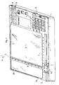
- la figure 1 est une vue schématique en perspective d'un dispositif conforme à l'invention,
- la figure 2 en est une coupe par un plan transversal A,
- la figure 3 en est une coupe de détail par un plan B perpendiculaire au précédent,
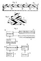
- la figure 4 est un schéma synoptique présentant les moyens de calcul du dispositif,
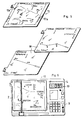
- la figure 5 est une vue en perspective schématique de cartes susceptibles d'équiper le dispositif,
- la figure 6 est une vue schématique en plan du dispositif muni d'une carte, en vue d'illustrer la mise en oeuvre du procédé conforme à l'invention.
- FIG. 1 is a schematic perspective view of a device according to the invention,
- FIG. 2 is a section thereof through a transverse plane A,
- FIG. 3 is a detailed section through a plane B perpendicular to the previous one,
- FIG. 4 is a block diagram showing the means of calculating the device,
- FIG. 5 is a schematic perspective view of cards capable of equipping the device,
- Figure 6 is a schematic plan view of the device with a card, to illustrate the implementation of the method according to the invention.
Le dispositif d'aide à la navigation représenté à titre d'exemple aux figures est constitué par un boîtier 1 de faible épaisseur et de forme générale rectangulaire, délimitant un plateau plat 2, rectangulaire ou carré, dit plateau de navigation, qui s'étend sur la plus grande partie de la surface du boîtier. Ce plateau de navigation 2 est situé légèrement en retrait par rapport à une bordure périphérique 3 légèrement en saillie en vue de délimiter un logement dans lequel est apte à se positionner une carte, les bords de celle-ci venant au contact de la bordure 3 de façon à lui conférer une position précise invariable par rapport au plateau 2. En t'exempte, la bordure périphérique 3 est interrompue par deux échancrures 3a, 3b pour le passage d'onglets d'identification des cartes.The navigation aid device shown by way of example in the figures consists of a
Sur un côté (4) du plateau 2, le boîtier 1 forme un support pour un système d'entrée de donnée et pour des moyens d'affichage, qui seront décrits plus loin; en outre, il permet de loger des moyens de calcul que comporte le dispositif ainsi que des moyens d'alimentation électrique des divers ensembles électroniques.On one side (4) of the
Le plateau de navigation 2 est pourvu d'un système d'étalonnage, consistant en un système de deux axes (X, Y) perpendiculaires entre eux, chaque axe étant parallèle à un bord du plateau et gradué à partir d'une origine.The
L'un des axes (X) est porté par un bord 5 du plateau et est gradué à partier d'une origine situé à proximité de l'extrémité gauche de ce bord.One of the axes (X) is carried by an
L'autre axe (Y) est porté par un curseur mobile 6 qui s'étend perpendiculairement au bord 5 sur toute la hauteur du plateau; ce curseur est gradué à partir d'une origine située à sa partie inférieure au voisinage du bord 5.The other axis (Y) is carried by a
Les graduations des axes X et Y sont conventionnelles et peuvent être quelconques; toutefois, on utilise de préférence des graduations possédant une même échelle sur les deux axes et qui représentent les unités de distance les plus usuellement utilisées dans le domaine concerné, à l'échelle des cartes les plus couramment employées. En particulier, le mile nautique (NM) (=1,852 km) est en général l'unité de distance utilisée en aéronautique et l'échelle des cartes les plus courantes est égale à 1/1 000.000e; dans ces conditions, la longueur de chaque graduation est de préférence égale à 1,852 mm. Ce choix fournit un avantage d'ordre pratique pour l'usager puisqu'il lui permet de disposer à tout instant sous les yeux d'une échelle des distances correspondant aux cartes les plus couramment utilisées.The graduations of the X and Y axes are conventional and can be any; however, use is preferably made of graduations having the same scale on the two axes and which represent the units of distance most commonly used in the field concerned, on the scale of the most commonly used maps. In particular, the nautical mile (NM) (= 1.852 km) is generally the unit of distance used in aeronautics and the scale of the most common maps is equal to 1 / 1,000,000th; under these conditions, the length of each graduation is preferably equal to 1.852 mm. This choice provides a practical advantage for the user since it allows him to have at all times under the eyes of a distance scale corresponding to the most commonly used maps.
En outre, pour un plateau 2 ayant des dimensions de l'ordre de 25 à 30 cm sur 15 à 20 cm, chaque coordonnée est représentée avec une excellente précision à l'aide de quatre chiffres au plus (exemple X= 120,3). Une telle dimension de plateau constitue un excellent compromis qui, à la fois, assure une grande facilité d'utilisation et de manipulation du dispositif (provenant d'un encombrement relativement faible) et permet à chaque carte, de couvrir une surface de territoire satisfaisante (environ 150 NM sur 100 NM) évitant des changements de cartes trop fréquents.In addition, for a
Comme le montrent les figures 1, 2 et 3, le curseur 6 est associé à des moyens de guidage en translation, adaptés pour permettre de le déplacer parallèlement au bord 5 sur toute la longueur de celui-ci; en l'exemple, ces moyens sont constitués par une glissière 7 prévue le long du bord 5, avec laquelle coopère le pied 6a du curseur, format coulisseau. De petites lâmes élastiques 8 autorisent le déplacement du curseur 6 sans risque de coincement, tout en préservant la perpendicularité de celui-ci par rapport au bord 5.As shown in FIGS. 1, 2 and 3, the
Par ailleurs, le dispositif comprend un ensemble électronique dont le schéma synoptique est fourni à la figure 4. Celui-ci est essentiellement constitué par un système d'entrée de données 9, une unité de calcul 10 constituée en l'exemple par un microprocesseur, une mémoire morte 11 (»ROM«) pour stocker un programme de calcul, une mémoire vive 12 (»RAM«) pour stocker les données renouvelables provenant du système d'entrée 9, des moyens d'affichage 13 et 14 des résultats et des interfaces 15 et 16 interposées entre l'unité de calcul 10 et les mémoires 11 et 12 ou les moyens d'affichage 13 et 14; de façon classique, ces interfaces sont en l'exemple constituées par des multiplexeurs et décodeurs.Furthermore, the device comprises an electronic assembly, the block diagram of which is provided in FIG. 4. This essentially consists of a
Le système d'entrée de données 9 est adapté pour permettre de générer des signaux électriques représentatifs des données qui sont composées sur un clavier que comprend ce système. Ce clavier est pourvu d'une pluralité de touches portées par le bord 4 du boîtier.The
En l'exemple, il comprend des touches numériques et des touches de fonction communes. Les touches numériques permettant de composer les chiffres d'une donnée (abscisse, ordonnée, relèvement) en leur affectant le cas échéant un signe (dont on verra l'utilité plus loin); certaines de ces touches font également office de touches de fonction et permettent d'affecter un code caractéristique de la nature de la donnée. Ces touches de fonction sont en l'exemple essentiellement au nombre de huit: abscisse conventionnelle x et ordonnée conventionnelle y du lieu de destination à atteindre, abscisse Xi, ordonnée Yi de la première station, relèvement Ri mesuré par rapport à cette première station, abscisse X2, ordonnée Y2 et relèvement R2 de la seconde station. Comme le montre la figure 1, ces touches de fonction sont marquée de signes d'identification appropriés.In the example, it includes number keys and common function keys. Numeric keys allowing to compose the digits of a data (abscissa, ordered, bearing) by assigning them if necessary a sign (whose usefulness will be seen further on); some of these keys also act as function keys and allow you to assign a code characteristic of the nature of the data. These function keys are essentially eight in number: conventional abscissa x and conventional ordinate y of the place of destination to be reached, abscissa Xi, ordinate Yi of the first station, bearing Ri measured with respect to this first station, abscissa X 2 , ordinate Y 2 and bearing R 2 of the second station. As shown in Figure 1, these function keys are marked with appropriate identification signs.
En outre, le clavier comprend, de façon classique, diverses touches, telles que touche de commande d'un calcul, touche d'effacement, touche de mise en mémoire (ou stockage), ainsi qu'un interrupteur d'alimentation électrique, et un sélecteur NAVIGATION/PERFORMANCE qui permet, soit d'activer le programme de navigation, soit de disposer les moyens de calcul en état d'effectuer d'autres calculs à partir de données spécifiques ou de certains résultats des calculs de navigation (calcul de la vitesse de l'avion, de la vitesse sol, du temps réel nécessaire pour atteindre un lieu de destination, de la dérive etc....). On ne donnera pas plus de détail sur les programmes de calculs correspondants, classiques en soi.In addition, the keyboard conventionally includes various keys, such as a control key. a calculation, erase key, memory (or storage) key, as well as an electrical power switch, and a NAVIGATION / PERFORMANCE selector which allows either to activate the navigation program or to have the means of calculation in a state to carry out other calculations from specific data or certain results of navigation calculations (calculation of airplane speed, ground speed, real time necessary to reach a place destination, drift etc ...). We will not give more details on the corresponding calculation programs, conventional in themselves.
Par ailleurs, les moyens d'affichage portés par le bord 4 du boîtier comprennent, en l'exemple, cinq afficheurs 13 à sept segments, en vue d'afficher les différents chiffres d'une information-résultat et un ensemble 14 de plusieurs diodes luminescentes correspondant chacune à la nature d'une information-résultat.Furthermore, the display means carried by the
En marge de chaque diode (qui s'allume lorsque le résultat s'inscrivant sur les afficheurs 13 correspond à celle-ci) est marquée d'indication du type d'information concernée, en l'exemple: Calc. (insertion de données), X (abscisse conventionnelle calculée de la position), Y (ordonnée de la position), Rm (cap du lieu de destination), D (distance du lieu de destination, v (vitesse du vent), r (direction du vent) et diverses informations complémentaires précitées susceptibles d'être calculées par les moyens de calcul (Vp: vitesse de l'avion, Vs: vitesse sol, Tr: temps réel pour atteindre une destination, d: dérive).In the margin of each diode (which lights up when the result appearing on the
Le programme de navigation qui est mémorisé dans la mémoire morte 11 est adapté pour gérer l'exécution des divers calculs de navigation à effectuer, essentiellement: calcul des coordonnées conventionnelles X et Y à partir des coordonnées et relèvements des deux stations X1, Yi, Ri, X2, Y2, R2, calcul du cap Rm à partir des coordonnées calculées X, Y et des coordonnées x et y du lieu de destination, enfin calcul de la distance D à partir des coordonnées calculées X, Y et des coordonnées x et y.The navigation program which is stored in the
Ces calculs peuvent être effectués par application des formules suivantes, à partir desquelles est établi le programme de navigation:

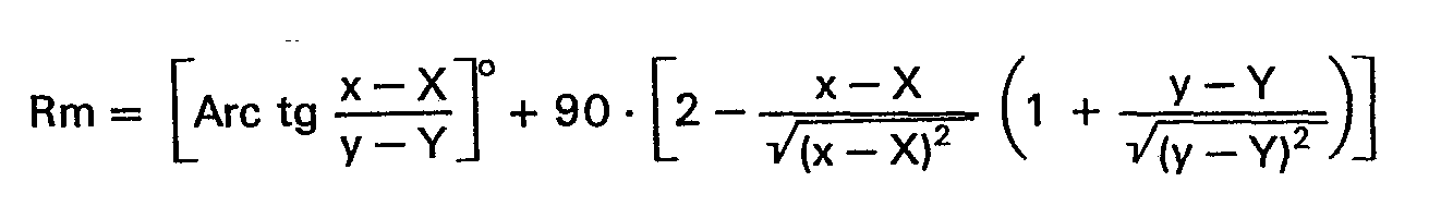
![]()
![]()
Pour le calcul de la distance D, le coefficient K est un coefficient tenant compte de l'échelle des cartes utilisées, de l'étalonnage du plateau 2 et de l'unité dans laquelle le pilot désire que la distance soit exprimée.For the calculation of the distance D, the coefficient K is a coefficient taking into account the scale of the maps used, the calibration of the
Dans l'exemple évoqué plus haut (échelle: 1/1 000.000e, étalonnage à la même échelle: 1 mm par km, unité de distance: mile nautique), ce coefficient est égal à 1,0799.In the example mentioned above (scale: 1 / 1,000,000th, calibration on the same scale: 1 mm per km, distance unit: nautical mile), this coefficient is equal to 1.0799.
Le dispositif de l'invention est de préférence équipé d'un jeu de cartes plastifiées éditées spécialement, qui couvrent un territoire donné divisé en régions correspondant chacune à une carte. Par exemple, le territoire français peut être représenté par environ 20 à 25 cartes au 1/1 000.000e, imprimées recto-verso sur des supports en papier plastifié (représentant un jeu de 10 à 15 support qui peuvent être stockés sous le plateau 2 à l'intérieur du boîtier).The device of the invention is preferably equipped with a set of specially edited plastic cards, which cover a given territory divided into regions each corresponding to a card. For example, French territory can be represented by approximately 20 to 25 maps per 1 / 1,000,000th, printed on both sides on plasticized paper supports (representing a set of 10 to 15 supports that can be stored under the
Chaque carte telle que carte 17 schématisée à la figure 5, comprend un onglet d'identification 17a portant des indications, recto-verso, propres à faciliter le choix de la carte qui correspond à la région de navigation. Les dimensions des cartes correspondent à celles du plateau de navigation 2.Each map such as
Elles portent toutes les indications géographiques classiques, avec les stations de radionavigation »VOR« ou »NDB« de la région et les aérodromes. Pour chaque station, la carte porte l'indication de la fréquence d'émission de celle-ci et de préférence, l'indication inscrite en chiffres de ses coordonnées conventionnelles ce qui permet une lecture directe sans utiliser le curseur 6. De même, les coordonnées conventionnelles de chaque aérodrome (ou des aérodromes principaux de la région) peuvent également être inscrites sur la carte dans le même but.They carry all the classic geographical indications, with the radionavigation stations "VOR" or "NDB" of the region and the aerodromes. For each station, the card bears the indication of its transmission frequency and preferably, the indication written in numbers of its conventional coordinates which allows direct reading without using the
De plus, la carte peut être dotée d'une marge périphérique telle que 17b, dans laquelle sont notées les stations de radionavigation »VOR« ou »NDB« proches de la région couverte par la carte, avec leur fréquence et leurs coordonnées conventionnelles. On peut ainsi prendre des relèvements par rapport à des stations situées en dehors de la carte, ce qui peut, dans certains cas, éviter des changements de cartes; l'abscisse ou l'ordonnée de telles stations peut être négative et la donnée est affectée du signe correspondant grâce à la touche appropriée du clavier.In addition, the map may have a peripheral margin such as 17b, in which the radio navigation stations "VOR" or "NDB" near the region covered by the map are noted, with their frequency and their conventional coordinates. It is thus possible to take bearings in relation to stations located outside the map, which can, in certain cases, avoid changes in cards; the abscissa or the ordinate of such stations can be negative and the data is assigned the corresponding sign by means of the appropriate key on the keyboard.
En outre, le jeu de cartes peut être complété par des cartes telles que 18 d'arrivée vers les aérodromes et d'approche de ceux-ci. Pour chaque aérodrome, la carte d'arrivée est imprimée au recto et la carte d'approche au verso du même support. L'échelle de l'une peut être de 1/50.000e et celle de l'autre 1/10.000e. Chacune de ces cartes porte les coordonnées conventionnelles de l'aérodrome et la trajectoire recommandée d'arrivée ou d'approche de l'aérodrome (avec les diverses caractéristiques de vol conseillées). Bien entendu, ces cartes portent également l'indication de deux stations »VOR« ou »NDB«, à portée radio de l'aérodrome, avec leurs caractéristiques.In addition, the deck of cards can be supplemented by cards such as 18 to and from the aerodromes. For each aerodrome, the arrival card is printed on the front and the approach card on the back of the same support. The scale of one can be 1 / 50,000 and that of the other 1 / 10,000. Each of these charts carries the conventional coordinates of the aerodrome and the recommended trajectory of arrival or approach to the aerodrome (with the various flight characteristics recommended). Of course, these cards also bear the indication of two stations "VOR" or "NDB", within radio range of the aerodrome, with their characteristics.
On a représenté à la figure 6 une vue schématique en plan du dispositif, en vue d'illustrer le procédé conforme à l'invention.There is shown in Figure 6 a schematic plan view of the device, to illustrate the method according to the invention.
Celui-ci consiste à sélectionner la carte 17 correspondant à la région survolée et à positionner celle-ci sur le plateau 2 dans le logement délimité par les bordures en saillie dudit plateau.This consists of selecting the
Deux stations »VOR« et/ou »NDB« sont ensuite choisies sur la carte et leurs coordonnées conventionnelles sont lues sur celle-ci. Dans le cas visé où ces coordonnées sont notées sur la carte, une simple lecture directe suffit. Il est à noter que ces coordonnées sont, non pas des coordonnées géographiques mais des coordonnées conventionnelles à 4 chiffres au plus, prises dans le système d'axe lié au plateau (axe du bord 5 et axe du curseur 6).Two stations »VOR« and / or »NDB« are then chosen on the map and their conventional coordinates are read on it. In the case where these coordinates are noted on the card, a simple direct reading is enough. It should be noted that these coordinates are, not geographic coordinates but conventional coordinates with 4 digits at most, taken from the axis system linked to the plate (
Dans le cas où ces coordonnées ne sont pas indiquées sur la carte (carte classique découpée par le pilote), la lecture de celles-ci consiste simplement à faire coulisser le curseur 6 parallèlement au bord 5 en vue de l'amener à passer par la station (ou plus généralement par le point concerné) et à lire une des coordonnées sur le curseur au niveau du point concerné (ordonnée) et l'autre sur le bord 5 au niveau du pied du curseur.In the event that these coordinates are not indicated on the map (classic map cut out by the pilot), reading these simply involves sliding the
Les coordonnées (Xi, Y,) (X2, Y2) des deux stations sont insérées dans la mémoire de stockage 12, en les composant sur le clavier 9 qui les traduit sous forme de signaux électriques codés.The coordinates (X i , Y,) (X 2 , Y 2 ) of the two stations are inserted into the
Le pilote mesure ensuite de façon classique les relèvements (R1, R2) des deux stations »VOR« ou »NDB« au moyen des instruments de radio-navigation »VOR« ou »ADF« de l'avion et insère ces relèvements dans la mémoire 12.The pilot then conventionally measures the bearings (R 1 , R 2 ) of the two stations "VOR" or "NDB" by means of the radio-navigation instruments "VOR" or "ADF" of the airplane and inserts these bearings in
Il lui suffi ensuite de déclencher le calcul pour obtenir les coordonnées conventionnelles X, Y de la position de l'avion. Les opérations logiques sont exécutées sur les signaux électriques représentatifs des données conformément à la formule indiquée plus haut et fournissent des signaux représentatifs des coordonnées X, Y qui sont successivement affichés sur les afficheurs 13 avec éclairement des diodes correspondantes.It then suffices to trigger the calculation to obtain the conventional X, Y coordinates of the position of the aircraft. The logic operations are executed on the electrical signals representative of the data in accordance with the formula indicated above and provide signals representative of the coordinates X, Y which are successively displayed on the
Le pilote repère alors sur la carte la position de l'aéronef au moyen des coordonnées lues sur les afficheurs. Il lui suffit de faire coulisser le curseur 6 en vue d'amener son pied sur la graduation correspondant à l'abscisse lue X et à repérer le point correspondant à la position, le long du curseur en regard de la graduation correspondant à l'ordonnée lue Y.The pilot then locates on the map the position of the aircraft by means of the coordinates read on the displays. He just has to slide the
On conçoit le caractère extrêmement simple et pratique des opérations qui sont demandées au pilote, opérations qui n'exigent aucun tracé géométrique.We understand the extremely simple and practical nature of the operations that are requested from the pilot, operations that do not require any geometric layout.
Pour obtenir le cap à suivre Rm pour atteindre un lieu de destination, les opérations se déroulent de façon similaire: lecture des coordonnées x, y de ce lieu au moyen du curseur 6, entrée de ces données sur le clavier 9, déclenchement du calcul selon la formule déjà indiquée utilisant les coordonnées de la position X, Y mises en mémoire à l'issu du calcul précédent, lecture du relèment Rm sur les afficheurs 13 avec identification de la nature de l'information lue par éclairement de la diode correspondante.To obtain the course to follow Rm to reach a place of destination, the operations are carried out in a similar way: reading of the x, y coordinates of this place by means of the
Pour obtenir la distance D séparant l'avion du lieu de destination, aucune nouvelle donnée n'est à insérer; le calcul correspondant s'effectue selon la formule déjà indiquée à partier de la position (X, Y) et du lieu de destination (x, y), le coefficient K étant préalablement mis en mémoire.To obtain the distance D separating the plane from the place of destination, no new data is to be inserted; the corresponding calculation is carried out according to the formula already indicated starting from the position (X, Y) and the place of destination (x, y), the coefficient K being previously stored.
Lorsque le pilot veut refaire un point sans avoir changé de région de navigation, il lui suffit d'insérer les nouveaux relèvements mesurés par rapport aux mêmes stations, ce qui lui fournit à nouveau des informations précises sur sa positions, le cap à suivre et la distance qui le sépare du lieu de destination.When the pilot wants to redo a point without having changed the navigation region, he just has to insert the new bearings measured with respect to the same stations, which again gives him precise information on his position, the course to follow and the distance from the place of destination.
De plus, il est aisé, au moyen du dispositif de l'invention, de déterminer la direction r et la vitesse v du vent réel agissant sur l'avion, en connaissant la vitesse de ce dernier.In addition, it is easy, by means of the device of the invention, to determine the direction r and the speed v of the real wind acting on the airplane, by knowing the speed of the latter.
Après avoir fait une première mesure de position (X, Y) et de relèvement (Rm), le pilote choisit sur la droite de relèvement calculé Rm, une destination intermédiaire (x;, y;) correspondant à un temps de parcours connu t à partir de la position initiale (X, Y) (par exemple 5 minutes).After having made a first position (X, Y) and bearing (Rm) measurement, the pilot chooses on the calculated bearing line Rm, an intermediate destination (x ;, y;) corresponding to a known journey time t to from the initial position (X, Y) (for example 5 minutes).
Au bout de ce temps, il détermine le nouveau cap R'm à suivre pour atteindre cette destination intermédiaire (x;, y;) et la distance D'qui le sépare de celle-ci.At the end of this time, it determines the new course R'm to follow in order to reach this intermediate destination (x ;, y;) and the distance D'which separates it from it.
La direction r du vent se déduit du nouveau cap R'm (r = R'm ± 180°) et la vitesse du vent se déduit de la distance D'et du temps t
Un programme correspondant à ces calcules est stocké dans la mémoire 11 afin d'assurer un affichage direct de ces informations sur les afficheurs 13 (k étant un coefficient dépendant des unités).A program corresponding to these calculations is stored in
On conçoit l'intérêt de l'invention qui permet de fournir au pilote les informations essentielles d'aides à la navigation dont il a besoin, au moyen d'un dispositif peu onéreux, et au terme d'opérations d'exécution rapide et simple, parfaitement compatibles avec la pratique attentive du pilotage.We can understand the advantage of the invention which makes it possible to provide the pilot with the essential navigation aid information he needs, by means of an inexpensive device, and at the end of rapid and simple execution operations. , perfectly compatible with the careful practice of piloting.
Claims (27)

Applications Claiming Priority (2)
| Application Number | Priority Date | Filing Date | Title |
|---|---|---|---|
| FR8101346 | 1981-01-22 | ||
| FR8101346A FR2498317A1 (en) | 1981-01-22 | 1981-01-22 | METHOD AND DEVICE FOR ASSISTING AERIAL OR MARITIME NAVIGATION |
Publications (3)
| Publication Number | Publication Date |
|---|---|
| EP0057032A2 EP0057032A2 (en) | 1982-08-04 |
| EP0057032A3 EP0057032A3 (en) | 1982-08-18 |
| EP0057032B1 true EP0057032B1 (en) | 1985-09-11 |
Family
ID=9254480
Family Applications (1)
| Application Number | Title | Priority Date | Filing Date |
|---|---|---|---|
| EP82200045A Expired EP0057032B1 (en) | 1981-01-22 | 1982-01-15 | Method and means for assisting aerial or maritime navigation |
Country Status (3)
| Country | Link |
|---|---|
| EP (1) | EP0057032B1 (en) |
| DE (1) | DE3266077D1 (en) |
| FR (1) | FR2498317A1 (en) |
Families Citing this family (5)
| Publication number | Priority date | Publication date | Assignee | Title |
|---|---|---|---|---|
| DE3218317A1 (en) * | 1982-05-14 | 1983-11-24 | Siemens AG, 1000 Berlin und 8000 München | Device in a central direction-finding station |
| EP0103847B1 (en) * | 1982-09-16 | 1988-12-07 | TELDIX GmbH | Navigation aid for vehicles |
| EP0126915B1 (en) * | 1983-05-27 | 1988-01-13 | VDO Adolf Schindling AG | Information input arrangement |
| FR2664379B2 (en) * | 1988-10-12 | 1994-09-16 | Allouard Guy | ELECTRONIC APPARATUS FOR AIDING AIR NAVIGATION FOR LIGHT AIRCRAFT. |
| US10036636B2 (en) * | 2015-03-19 | 2018-07-31 | Vricon Systems Aktiebolag | Position determining unit and a method for determining a position of a land or sea based object |
Family Cites Families (7)
| Publication number | Priority date | Publication date | Assignee | Title |
|---|---|---|---|---|
| NL80099C (en) * | 1946-01-23 | |||
| US2710962A (en) * | 1953-11-23 | 1955-06-14 | Collins Radio Co | Punch card controlled aircraft navigation computer |
| GB868398A (en) * | 1958-04-17 | 1961-05-17 | Kelvin & Hughes Ltd | Improvements in and relating to computing apparatus |
| DE1548416C3 (en) * | 1966-11-28 | 1974-01-31 | Decca Ltd., London | Arrangement for position display for a moving vehicle, in particular an airplane |
| US3882501A (en) * | 1974-02-11 | 1975-05-06 | Northrop Corp | System for determining speed and heading of airborne equipment with rectilinear coordinate positions |
| FR2291479A1 (en) * | 1974-11-18 | 1976-06-11 | Sfena | METHOD AND APPARATUS FOR INDICATING THE GEOGRAPHICAL POSITION OF A PILOT VEHICLE |
| US4086632A (en) * | 1976-09-27 | 1978-04-25 | The Boeing Company | Area navigation system including a map display unit for establishing and modifying navigation routes |
-
1981
- 1981-01-22 FR FR8101346A patent/FR2498317A1/en active Granted
-
1982
- 1982-01-15 EP EP82200045A patent/EP0057032B1/en not_active Expired
- 1982-01-15 DE DE8282200045T patent/DE3266077D1/en not_active Expired
Also Published As
| Publication number | Publication date |
|---|---|
| FR2498317A1 (en) | 1982-07-23 |
| DE3266077D1 (en) | 1985-10-17 |
| FR2498317B1 (en) | 1984-03-16 |
| EP0057032A2 (en) | 1982-08-04 |
| EP0057032A3 (en) | 1982-08-18 |
Similar Documents
| Publication | Publication Date | Title |
|---|---|---|
| FR2694392A1 (en) | Method of assisting navigation | |
| EP0694762B1 (en) | Interactive navigational aid for aircraft | |
| FR2920242A1 (en) | METHOD AND DEVICE FOR ANNOTATING ELECTRONIC MAPPING FUNDS | |
| EP0057032B1 (en) | Method and means for assisting aerial or maritime navigation | |
| US6658746B2 (en) | Navigation plotter | |
| Száz et al. | Success of sky-polarimetric Viking navigation: Revealing the chance Viking sailors could reach Greenland from Norway | |
| US8365425B2 (en) | Chart specific navigation plotter and method for inexpensive production thereof | |
| US4208805A (en) | Navigational calculating device | |
| FR2623911A1 (en) | SYSTEM FOR MONITORING OR HELPING MARITIME NAVIGATION OR TRAFFIC | |
| Lobo-Guerrero | On the epistemology of maps and mapping: De la Cosa, Mercator and the making of spatial imaginaries | |
| Jeffers | Hydrographic manual | |
| EP0331544A1 (en) | Device for directly reading the course on a map which has to be followed by an aircraft or watercraft | |
| Edwards | Who needs GPS? The forgotten story of Etak’s amazing 1985 car navigation system | |
| FR2920580A1 (en) | METHOD FOR SIMPLIFYING THE DISPLAY OF STATIONARY ELEMENTS OF AN EMBEDDED DATA BASE | |
| Johnson et al. | The role of trust and interaction in GPS related accidents: a human factors safety assessment of the global positioning system (GPS) | |
| FR2664379A2 (en) | Electronic apparatus for aiding the establishment of aerial navigation for light aircraft | |
| US2073352A (en) | Adjustable direction-finder chart | |
| FR2563624A1 (en) | Aircraft navigation and object identification system | |
| Featherstone | Outdoor guide to using your GPS | |
| Porathe | Ship navigation | |
| EP2702359B1 (en) | Method and device for creating itinerary and navigation maps with synthetic data | |
| Carter et al. | The Newcomb‐Michelson velocity of light experiments | |
| FR2741712A1 (en) | Aircraft navigation device | |
| McConnel | US Coast and Geodetic Survey Nautical Charts: A Cartographic History | |
| KOSIAN | GISing dead-reckoning; historic maritime maps in GIS |
Legal Events
| Date | Code | Title | Description |
|---|---|---|---|
| PUAI | Public reference made under article 153(3) epc to a published international application that has entered the european phase |
Free format text: ORIGINAL CODE: 0009012 |
|
| PUAL | Search report despatched |
Free format text: ORIGINAL CODE: 0009013 |
|
| AK | Designated contracting states |
Designated state(s): BE CH DE GB IT NL SE |
|
| AK | Designated contracting states |
Designated state(s): BE CH DE GB IT NL SE |
|
| 17P | Request for examination filed |
Effective date: 19820923 |
|
| GRAA | (expected) grant |
Free format text: ORIGINAL CODE: 0009210 |
|
| AK | Designated contracting states |
Designated state(s): BE CH DE GB IT LI NL SE |
|
| PG25 | Lapsed in a contracting state [announced via postgrant information from national office to epo] |
Ref country code: NL Effective date: 19850911 Ref country code: IT Free format text: LAPSE BECAUSE OF FAILURE TO SUBMIT A TRANSLATION OF THE DESCRIPTION OR TO PAY THE FEE WITHIN THE PRESCRIBED TIME-LIMIT;WARNING: LAPSES OF ITALIAN PATENTS WITH EFFECTIVE DATE BEFORE 2007 MAY HAVE OCCURRED AT ANY TIME BEFORE 2007. THE CORRECT EFFECTIVE DATE MAY BE DIFFERENT FROM THE ONE RECORDED. Effective date: 19850911 |
|
| PG25 | Lapsed in a contracting state [announced via postgrant information from national office to epo] |
Ref country code: SE Effective date: 19850930 |
|
| REF | Corresponds to: |
Ref document number: 3266077 Country of ref document: DE Date of ref document: 19851017 |
|
| PG25 | Lapsed in a contracting state [announced via postgrant information from national office to epo] |
Ref country code: LI Effective date: 19860131 Ref country code: CH Effective date: 19860131 Ref country code: BE Effective date: 19860131 |
|
| NLV1 | Nl: lapsed or annulled due to failure to fulfill the requirements of art. 29p and 29m of the patents act | ||
| PLBE | No opposition filed within time limit |
Free format text: ORIGINAL CODE: 0009261 |
|
| STAA | Information on the status of an ep patent application or granted ep patent |
Free format text: STATUS: NO OPPOSITION FILED WITHIN TIME LIMIT |
|
| BERE | Be: lapsed |
Owner name: MESSUD MICHEL Effective date: 19860131 |
|
| 26N | No opposition filed | ||
| REG | Reference to a national code |
Ref country code: CH Ref legal event code: PL |
|
| GBPC | Gb: european patent ceased through non-payment of renewal fee | ||
| PG25 | Lapsed in a contracting state [announced via postgrant information from national office to epo] |
Ref country code: DE Effective date: 19881001 |
|
| PG25 | Lapsed in a contracting state [announced via postgrant information from national office to epo] |
Ref country code: GB Free format text: LAPSE BECAUSE OF NON-PAYMENT OF DUE FEES Effective date: 19881121 |