EP0056915B1 - Dispositif de fusion par induction directe en cage froide avec confinement électromagnétique supplémentaire de la charge - Google Patents
Dispositif de fusion par induction directe en cage froide avec confinement électromagnétique supplémentaire de la charge Download PDFInfo
- Publication number
- EP0056915B1 EP0056915B1 EP81401845A EP81401845A EP0056915B1 EP 0056915 B1 EP0056915 B1 EP 0056915B1 EP 81401845 A EP81401845 A EP 81401845A EP 81401845 A EP81401845 A EP 81401845A EP 0056915 B1 EP0056915 B1 EP 0056915B1
- Authority
- EP
- European Patent Office
- Prior art keywords
- inductor
- cold
- cage
- load
- confinement
- Prior art date
- Legal status (The legal status is an assumption and is not a legal conclusion. Google has not performed a legal analysis and makes no representation as to the accuracy of the status listed.)
- Expired
Links
- 238000002844 melting Methods 0.000 title claims description 29
- 230000008018 melting Effects 0.000 title claims description 29
- 230000006698 induction Effects 0.000 title claims description 13
- 229910052751 metal Inorganic materials 0.000 claims description 20
- 239000002184 metal Substances 0.000 claims description 20
- 239000000126 substance Substances 0.000 claims description 14
- 238000000034 method Methods 0.000 claims description 13
- 150000002739 metals Chemical class 0.000 claims description 9
- 230000008569 process Effects 0.000 claims description 9
- VYPSYNLAJGMNEJ-UHFFFAOYSA-N Silicium dioxide Chemical compound O=[Si]=O VYPSYNLAJGMNEJ-UHFFFAOYSA-N 0.000 claims description 7
- 239000002893 slag Substances 0.000 claims description 7
- 238000001816 cooling Methods 0.000 claims description 6
- 239000007787 solid Substances 0.000 claims description 5
- OYPRJOBELJOOCE-UHFFFAOYSA-N Calcium Chemical compound [Ca] OYPRJOBELJOOCE-UHFFFAOYSA-N 0.000 claims description 3
- 150000001642 boronic acid derivatives Chemical class 0.000 claims description 3
- 229910052791 calcium Inorganic materials 0.000 claims description 3
- 239000011575 calcium Substances 0.000 claims description 3
- WUKWITHWXAAZEY-UHFFFAOYSA-L calcium difluoride Chemical compound [F-].[F-].[Ca+2] WUKWITHWXAAZEY-UHFFFAOYSA-L 0.000 claims description 3
- 239000012809 cooling fluid Substances 0.000 claims description 3
- 239000000377 silicon dioxide Substances 0.000 claims description 3
- 238000007792 addition Methods 0.000 claims description 2
- 150000001875 compounds Chemical class 0.000 claims 1
- 239000007769 metal material Substances 0.000 claims 1
- 238000010438 heat treatment Methods 0.000 description 12
- 239000004020 conductor Substances 0.000 description 10
- 230000000694 effects Effects 0.000 description 9
- 239000000463 material Substances 0.000 description 8
- 230000004927 fusion Effects 0.000 description 6
- RYGMFSIKBFXOCR-UHFFFAOYSA-N Copper Chemical compound [Cu] RYGMFSIKBFXOCR-UHFFFAOYSA-N 0.000 description 5
- 229910045601 alloy Inorganic materials 0.000 description 5
- 239000000956 alloy Substances 0.000 description 5
- 238000005266 casting Methods 0.000 description 5
- 229910052802 copper Inorganic materials 0.000 description 5
- 239000010949 copper Substances 0.000 description 5
- 238000005339 levitation Methods 0.000 description 5
- 239000007788 liquid Substances 0.000 description 5
- 239000000919 ceramic Substances 0.000 description 4
- 239000012530 fluid Substances 0.000 description 4
- 229910001092 metal group alloy Inorganic materials 0.000 description 4
- 239000000203 mixture Substances 0.000 description 4
- XEEYBQQBJWHFJM-UHFFFAOYSA-N Iron Chemical compound [Fe] XEEYBQQBJWHFJM-UHFFFAOYSA-N 0.000 description 3
- WYTGDNHDOZPMIW-RCBQFDQVSA-N alstonine Natural products C1=CC2=C3C=CC=CC3=NC2=C2N1C[C@H]1[C@H](C)OC=C(C(=O)OC)[C@H]1C2 WYTGDNHDOZPMIW-RCBQFDQVSA-N 0.000 description 3
- 239000011651 chromium Substances 0.000 description 3
- 230000008878 coupling Effects 0.000 description 3
- 238000010168 coupling process Methods 0.000 description 3
- 238000005859 coupling reaction Methods 0.000 description 3
- 239000000945 filler Substances 0.000 description 3
- 238000003756 stirring Methods 0.000 description 3
- VYZAMTAEIAYCRO-UHFFFAOYSA-N Chromium Chemical compound [Cr] VYZAMTAEIAYCRO-UHFFFAOYSA-N 0.000 description 2
- 229910000990 Ni alloy Inorganic materials 0.000 description 2
- 239000002671 adjuvant Substances 0.000 description 2
- 229910052784 alkaline earth metal Inorganic materials 0.000 description 2
- PNEYBMLMFCGWSK-UHFFFAOYSA-N aluminium oxide Inorganic materials [O-2].[O-2].[O-2].[Al+3].[Al+3] PNEYBMLMFCGWSK-UHFFFAOYSA-N 0.000 description 2
- 230000008901 benefit Effects 0.000 description 2
- 229910010293 ceramic material Inorganic materials 0.000 description 2
- 239000002826 coolant Substances 0.000 description 2
- 239000011810 insulating material Substances 0.000 description 2
- 238000009413 insulation Methods 0.000 description 2
- 238000004519 manufacturing process Methods 0.000 description 2
- 239000012768 molten material Substances 0.000 description 2
- 239000002245 particle Substances 0.000 description 2
- 239000000843 powder Substances 0.000 description 2
- 230000009467 reduction Effects 0.000 description 2
- 239000011819 refractory material Substances 0.000 description 2
- 239000003870 refractory metal Substances 0.000 description 2
- 239000004065 semiconductor Substances 0.000 description 2
- 150000004760 silicates Chemical class 0.000 description 2
- 238000004804 winding Methods 0.000 description 2
- JBRZTFJDHDCESZ-UHFFFAOYSA-N AsGa Chemical compound [As]#[Ga] JBRZTFJDHDCESZ-UHFFFAOYSA-N 0.000 description 1
- 229910004261 CaF 2 Inorganic materials 0.000 description 1
- 229910000599 Cr alloy Inorganic materials 0.000 description 1
- 229910000881 Cu alloy Inorganic materials 0.000 description 1
- 229910000640 Fe alloy Inorganic materials 0.000 description 1
- KRHYYFGTRYWZRS-UHFFFAOYSA-M Fluoride anion Chemical compound [F-] KRHYYFGTRYWZRS-UHFFFAOYSA-M 0.000 description 1
- PXGOKWXKJXAPGV-UHFFFAOYSA-N Fluorine Chemical compound FF PXGOKWXKJXAPGV-UHFFFAOYSA-N 0.000 description 1
- 229910001218 Gallium arsenide Inorganic materials 0.000 description 1
- 241001275902 Parabramis pekinensis Species 0.000 description 1
- XUIMIQQOPSSXEZ-UHFFFAOYSA-N Silicon Chemical compound [Si] XUIMIQQOPSSXEZ-UHFFFAOYSA-N 0.000 description 1
- 230000006978 adaptation Effects 0.000 description 1
- 239000003513 alkali Substances 0.000 description 1
- 150000001342 alkaline earth metals Chemical class 0.000 description 1
- 239000002585 base Substances 0.000 description 1
- 230000015572 biosynthetic process Effects 0.000 description 1
- 238000005219 brazing Methods 0.000 description 1
- 229910001634 calcium fluoride Inorganic materials 0.000 description 1
- 239000003638 chemical reducing agent Substances 0.000 description 1
- 229910052804 chromium Inorganic materials 0.000 description 1
- 239000011248 coating agent Substances 0.000 description 1
- 238000000576 coating method Methods 0.000 description 1
- 238000011109 contamination Methods 0.000 description 1
- 238000009749 continuous casting Methods 0.000 description 1
- -1 copper or chromium Chemical class 0.000 description 1
- 239000013078 crystal Substances 0.000 description 1
- 238000006073 displacement reaction Methods 0.000 description 1
- 239000004744 fabric Substances 0.000 description 1
- 239000011737 fluorine Substances 0.000 description 1
- 229910052731 fluorine Inorganic materials 0.000 description 1
- 239000010436 fluorite Substances 0.000 description 1
- 229910052732 germanium Inorganic materials 0.000 description 1
- GNPVGFCGXDBREM-UHFFFAOYSA-N germanium atom Chemical compound [Ge] GNPVGFCGXDBREM-UHFFFAOYSA-N 0.000 description 1
- 150000004820 halides Chemical class 0.000 description 1
- 229910001026 inconel Inorganic materials 0.000 description 1
- 239000000411 inducer Substances 0.000 description 1
- 230000001939 inductive effect Effects 0.000 description 1
- 238000002955 isolation Methods 0.000 description 1
- 238000005304 joining Methods 0.000 description 1
- 238000012423 maintenance Methods 0.000 description 1
- 229910044991 metal oxide Inorganic materials 0.000 description 1
- 150000004706 metal oxides Chemical class 0.000 description 1
- 238000002156 mixing Methods 0.000 description 1
- 229910052759 nickel Inorganic materials 0.000 description 1
- PXHVJJICTQNCMI-UHFFFAOYSA-N nickel Substances [Ni] PXHVJJICTQNCMI-UHFFFAOYSA-N 0.000 description 1
- 238000005192 partition Methods 0.000 description 1
- 230000002093 peripheral effect Effects 0.000 description 1
- 230000035699 permeability Effects 0.000 description 1
- 229910000753 refractory alloy Inorganic materials 0.000 description 1
- 239000011214 refractory ceramic Substances 0.000 description 1
- 239000003507 refrigerant Substances 0.000 description 1
- 238000000926 separation method Methods 0.000 description 1
- 229910052710 silicon Inorganic materials 0.000 description 1
- 239000010703 silicon Substances 0.000 description 1
- 239000002904 solvent Substances 0.000 description 1
- 238000009617 vacuum fusion Methods 0.000 description 1
- XLYOFNOQVPJJNP-UHFFFAOYSA-N water Substances O XLYOFNOQVPJJNP-UHFFFAOYSA-N 0.000 description 1
- 238000003466 welding Methods 0.000 description 1
Images
Classifications
-
- F—MECHANICAL ENGINEERING; LIGHTING; HEATING; WEAPONS; BLASTING
- F27—FURNACES; KILNS; OVENS; RETORTS
- F27B—FURNACES, KILNS, OVENS OR RETORTS IN GENERAL; OPEN SINTERING OR LIKE APPARATUS
- F27B14/00—Crucible or pot furnaces
- F27B14/06—Crucible or pot furnaces heated electrically, e.g. induction crucible furnaces with or without any other source of heat
- F27B14/061—Induction furnaces
- F27B14/063—Skull melting type
-
- H—ELECTRICITY
- H05—ELECTRIC TECHNIQUES NOT OTHERWISE PROVIDED FOR
- H05B—ELECTRIC HEATING; ELECTRIC LIGHT SOURCES NOT OTHERWISE PROVIDED FOR; CIRCUIT ARRANGEMENTS FOR ELECTRIC LIGHT SOURCES, IN GENERAL
- H05B6/00—Heating by electric, magnetic or electromagnetic fields
- H05B6/02—Induction heating
- H05B6/22—Furnaces without an endless core
-
- F—MECHANICAL ENGINEERING; LIGHTING; HEATING; WEAPONS; BLASTING
- F27—FURNACES; KILNS; OVENS; RETORTS
- F27D—DETAILS OR ACCESSORIES OF FURNACES, KILNS, OVENS OR RETORTS, IN SO FAR AS THEY ARE OF KINDS OCCURRING IN MORE THAN ONE KIND OF FURNACE
- F27D99/00—Subject matter not provided for in other groups of this subclass
- F27D99/0001—Heating elements or systems
- F27D99/0006—Electric heating elements or system
- F27D2099/0015—Induction heating
- F27D2099/0016—Different magnetic fields, e.g. two coils, different characteristics of the same coil along its length or different parts of the same coil used
Definitions
- the invention relates to a device for direct induction melting in a cold cage, known as a “self-crucible”, with additional electromagnetic confinement of the charge, in order to separate it from the inner side wall of this cage.
- the charge to be melted is generally introduced into the cold cage, the bottom of which is closed by means of a hollow refractory or metallic insulating plate and cooled from above in a powdery or granular form.
- a hollow refractory or metallic insulating plate When it consists of a mixture of materials, at least one of which is cold insulating, the latter agglomerates, during melting, in the vicinity of the inner wall of the cold cage so as to form a thin sheath or electrically insulating film covering it.
- the load is metallic (that is to say metal or metal alloys) and cold conductive
- this sheath formed in contact with the cold wall is also conductive and puts the insulated elements (segments in tube copper) of the cage in short circuit.
- the electromagnetic confinement of a molten metal flow by means of an axial alternating magnetic field is known per se, for example, from the publications GB-A893445, FR-A-1 509 962, 2106545, 2160281, 2 316 026 and 2396612
- the axial magnetic confinement field is generated using an inductor supplied with alternating current, coaxially surrounding the crucible or the nozzle carrying the casting, substantially at its lower orifice.
- the ingot has surface irregularities in the form of longitudinal ridges, at the locations of the partitions between the segments of the cage, where the cooling effect is less effective.
- a horizontal oven by direct induction with electromagnetic levitation of the load of solid conductive material has been described in the publication FR-A-1 508 992, where an inductor with three longitudinal strands (parallel to the horizontal axis), two of which are connected in parallel and one of which (the lower one) is connected in series with the others to form a levitation cradle, is surrounded by a cylindrical or solenoidal monospire inductor which ensures the heating of the metallic body and contributes to its maintenance in levita tion, especially when it is in fusion.
- Such a horizontal furnace without a crucible cannot be used with divided loads (powdery or grainy) and does not allow continuous casting or drawing of ingots or crystals.
- its maximum load is limited to a few kilograms due to the force necessary for levitation which is opposed to gravitation.
- these “anti-parallel” inductors are formed using several conductive strands, parallel to the vertical axis of the ingot and connected in series so that the currents which flow through the neighboring strands are respectively in opposite directions, in order to 'exert on the molten upper part of the ingot electromagnetic forces of repulsion (confinement) which are added to those generated by the main inductor and which are analogous to those of the above-mentioned publication DE-B-1 147 714.
- the subject of the present invention is a device for direct induction melting in a cage whose cylindrical side wall is formed by one or more “antiparallel” inductors which serve at the same time as a cold sheath and an additional confinement device, making it possible in particular to receive pulverulent or granular fillers (divided into particles) of various materials which may be insulating or cold conducting or made up of mixtures of such materials.
- This fusion device is oriented vertically to allow the casting of the molten material or the drawing of ingots (known per se) and, therefore, the additional confinement magnetic field does not have to overcome gravitation and can act on the molten part of the charge, when it is cold insulating, to facilitate the formation of the agglomerate shell or gangue which replaces the crucible and whose increased thickness ensures better thermal insulation of the molten part.
- the magnetic field generated by the currents flowing through the sections of the cage can also act on the upper non-melted part of the load, if their intensity exceeds a certain threshold.
- the cold side wall of the cage is arranged such that it constitutes at the same time a confinement inductor of a type known per se, which is supplied by a second power generator of a high or medium second frequency and which comprises, in addition to the juxtaposed tubular sections, electrical connection means connecting together the adjacent ends of two neighboring tubular sections, so that these are respectively traversed by the same alternating current in opposite directions, generating in the conductive part from the periphery of the load of the additional confinement forces.
- a confinement inductor of a type known per se, which is supplied by a second power generator of a high or medium second frequency and which comprises, in addition to the juxtaposed tubular sections, electrical connection means connecting together the adjacent ends of two neighboring tubular sections, so that these are respectively traversed by the same alternating current in opposite directions, generating in the conductive part from the periphery of the load of the additional confinement forces.
- These electrical connection means can be constituted by conductive plates or transverse tube sections which join together, for example, by one of their respective adjacent ends, two neighboring tubular sections so as to form pin-shaped segments. to hair which are then juxtaposed electrically insulated to form the side wall of the cold cage.
- the hairpin segments forming the side wall are respectively electrically connected in parallel, in series or in various series-parallel combinations, so that a set of inductor elements thus connected can have an impedance adapted to the frequency of the second generator.
- the additional confining power provided by the second generator is a function of the diameter and the height of the cold cage and, consequently, of the volume of the load. It is generally between one tenth and one fifth of the power supplied by the first generator to the main inductor surrounding the cage.
- a small proportion of a cold insulating substance is added to the charge to be melted, when all of its components are metallic (cold conductive). a melting point lower than that of the metal or alloy, to form a slag.
- This slag preferably fluorite (or calcium fluoride) or silica, optionally mixed with adjuvants such as borates, has in the molten state a surface tension significantly lower than that of the metal to which it is mixed in the state pulverulent and it is, therefore, expelled from the molten metal stirred towards the periphery of the charge, where under the effect of the cold cage it solidifies becoming again insulating.
- a proportion by weight of 0.5 to 1.5 percent is used in relation to the total weight of the filler.
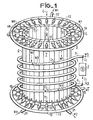
- Figure 1 is a schematic perspective view of a melting device by direct induction in a cold cage of the prior art.
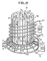
- Figure 2 is a schematic view in pers pective of an embodiment of the direct induction fusion device with additional electromagnetic confinement of the charge, in which for the simplicity of the drawing, the hairpin segments are connected in parallel.
- the conventional melting device of FIG. 1 comprises a heating inductor 1 of helical shape, made of copper tube and comprising several turns which cover a predetermined height.
- the two ends 3, 4 of this inductor 1 are respectively combined here at two output terminals (low impedance, for example) of a first power generator 2 which can generate an alternating current 1 1 high (30kHz-10MHz) or medium (1-30 kHz) frequencies (industrial) which are respectively intended for the fusion of cold insulating refractory materials, such as oxides or silicates for example, or semiconductors, such as silicon, germanium or gallium arsenide, for example, and that of cold conductive materials, such as metals or metal alloys.
- the power supplied to the inductor 1 is a function, in particular, of the nature (melting point, resistivity cold and hot, relative permeability up to the Curie point etc.) of the material, the volume of the charge to be melted (that is to say the diameter of the cold cage and the height of the inductor 1) and the coupling between the load and the inductor (the thickness of the cage).
- the generator 2 must therefore be dimensioned so as to provide a power of between 50 and 250 kilowatts, for example.
- the cold cage or “self-crucible 5 includes a cylindrical side wall 6 with vertical axis of symmetry, composed of a large number of juxtaposed tubular segments 7, which are of elongated shape and oriented parallel to the geometric axis or to the generator of the cylinder that they form together.
- These segments 7 can be produced in metal tube sections of rectangular, circular, trapezoidal or delimited section, as in FIG. 1, by two concentric arcs of circle whose center coincides with the axis of the wall 6 and by two sections radial lines having an intersection on this axis (see, for example, FR-A-1 492 063).
- the walls (radial) of the adjacent segments 7 which are located opposite, are insulated from each other by means of an insulating coating 8 in the form of an electrically insulating layer deposited, for example, in a ceramic material (alumina or other) by "shooping", or by means of rigid separation plates or felt tapes or fabrics of a similar insulating material, preferably refractory, inserted between these walls.
- an insulating coating 8 in the form of an electrically insulating layer deposited, for example, in a ceramic material (alumina or other) by "shooping", or by means of rigid separation plates or felt tapes or fabrics of a similar insulating material, preferably refractory, inserted between these walls.
- each of the ends of the tubular sections forming the segments 7 is closed by a transverse plate 10 and provided with tubular connection end pieces 11, oriented in radial projection towards the outside.
- the circulation of the cooling fluid is ensured by means of an intake collecting ring 12 and an evacuation collecting ring 13 of diameters greater than that outside of the wall 6 as well as that of the heating inductor 1.
- These collecting rings 12 and 13 are respectively provided with connection end pieces 14 and 15, oriented inwardly projecting radially, which are hydraulically connected to those 11 of the segments 7 by means of insulating tubular seals 16, preferably flexible, of so as to maintain the electrical isolation between the segments 7.
- These collector rings 12, 13 are respectively joined using other tubular ends 17, 18 to a circuit of the refrigerant fluid (not shown) whose circulation takes place in the direction of the arrows W1.
- the bottom of the cold cage 5 is closed using a base or sole 19 also cooled, either in the form of a hollow metal disc connected by two end pieces 20, 21 to another fluid circuit represented by arrows W2, or in the form of a ceramic disc (see, for example, GB-A-1 130 070), the underside of which can be sprinkled, for example.
- This hearth 19 can be produced using sectors isolated from each other or in the form of a ring crossed by a heated discharge nozzle for the molten charge (see FR-A-1 188576 or 2 054 464 , for example).
- the hearth 19 When the hearth 19 is made of a conductive material and the charge to be melted is conductive when cold, it may be advantageous to completely cover its upper face with a layer or a lining of insulating material (ceramic).
- the outer (annular) part of the upper face of the floor 19, which is in contact with the lower end of the side wall 6, is preferably isolated in all cases from the latter, for example, by means of '' a ceramic felt washer or a powder bed of an insulating refractory material (alumina, for example).
- the heating inductor 1 which surrounds the side wall 6 of the cage 5 and which ensures the direct induction melting of the charge and the stirring of the liquid bath, is also produced in a tube and connected to a fluid circuit cooling symbolized by the arrows W3. It will also be noted that in the cage 5, a necking effect has been observed produced by the inductor 1 on the part of the liquid bath which is at its level.
- the load is introduced into the cage 5 in powder or granular form by means of a hopper (not shown) from the top, in the direction of the arrow C.
- FIG. 2 is a perspective view of a possible embodiment of a vertical melting device with additional electromagnetic confinement of the charge, according to the invention.
- the segments 70 forming the side wall 60 of the cold cage 50 have been produced by means of tubular elements in the form of hairpins (or “U”) using two sections of parallel tube 71, 72, placed side by side insulated from each other by a slot 73 which can be closed by felt or by a ceramic layer, and one of which 71 has an end hydraulically and electrically connected to that, adjacent of the neighboring section 72 by means of a transverse (circumferential) joining section 74, perpendicular to the two parallel sections 71, 72.
- hairpins or “U”
- These segments 70 are juxtaposed as in the state of the art, so as to form the cylindrical side wall 60 of the cage 50, the bottom of which is closed by a conventional sole 19 (see FIG. 1 and the state of the art mentioned above. ).
- the free adjacent (unconnected) ends of the sections 71, 72 forming the same segment 70 are respectively hydraulically and electrically connected by joints or metallic tubular sections 22, 23 conductive, one of which (22) is perpendicular to the vertical axis of the sheath 50 and the other (23) inclined with respect to this axis, to two hollow metal collecting rings 120, 130 of which the first (120) comprises the inlet nozzle 17 and the second (130) the nozzle 18 for evacuating the coolant from the cage 50, the circulation of which is indicated by the arrows W1.
- the respective electrical connection between the collector rings 120, 130 and the respective ends of the hairpin segments 70 makes it possible, by connecting them respectively to the two output terminals of a second AC power generator 24, to pass through the two parallel sections 71, 72 of the alternating electric currents respectively in opposite directions.
- centripetal forces that is to say repulsion forces, substantially uniformly distributed at the periphery of the bath and oriented radially in the direction of its geometric axis.
- the confinement forces generated by the cage 50 according to the invention also act on the parts of the solid charge but having exceeded the inducibility temperature, which are then separated from its inner wall and replaced by particles (grains) insulating from the substance.
- the preferred method of using the melting device by direct induction in a cold cage, with additional electromagnetic confinement of the charge, when the latter is purely metallic, consists in adding to it in the divided state (pulverulent or granular), a small amount of a cold insulating substance and having a melting temperature close to its inducibility temperature and lower than that of the metal or alloy, to form a slag.
- This slag having to present in the molten state a surface tension notably lower than that of the metallic part of the load, is precipitated from the mass of molten metal towards its periphery, where by cooling under the effect of the cold cage 50, it fills the space provided by the confining forces and becomes insulating and solid again in contact with the interior wall of the latter.
- the slag loses its inducibility under the effect of the cage 50 and fills the peripheral space between the latter and the load, forming an electrically and thermally insulating shell therein.
- the mixture constituting the filler comprises in this case a proportion by weight of between 0.5 and 1.5 percent of the slag-forming substance, which is preferably constituted by fluorine (or calcium fluoride-CaF 2 ) or silica, optionally mixed with adjuvants such as borates allowing its melting point to be lowered to around 1400 ° C.
- the cage 50 therefore comprises juxtaposed hairpin inductors formed by the segments 70 and connected in parallel by means of the two collector rings 120, 130 which are respectively connected to the two low-impedance output terminals formed, for example, by the terminals of a secondary winding of an adaptation transformer (not shown) whose primary winding is connected to the terminals of the second generator 24.
- These inductors (in U 70) are each supplied with a current 1 2 / N of a few tens of effective amperes (where N is the number of segments 70 forming the cage 50), the exact intensity of which is then determined experimentally as a function of the dimensions of the bath and of the necking effect already provided by the heating inductor 1, so that they produce an adequate additional electromagnetic confinement of the load.
- a significantly lower power than that consumed by the inductor 1 is sufficient to supply the segments 70 of the cage 50 in parallel and to obtain sufficient confinement of the bath.
- the second generator 24 supplying the inductors of the cage 50 in parallel will therefore have to supply, for example, a power which is between one fifth and one tenth of that supplied by the first generator 2 to the inductor 1 (from 50 to 250 kW ).
- a power of the order of a few kilowatts to a few tens of kilowatts (10 to 30 kW, for example) is sufficient for the electromagnetic confinement of charges of metal or of metal alloys.
- the same frequency ranges will be used for the fusion-stirring and for the confinement by the cage 50, that is to say the high frequencies from 30 kHz to 10 MHz for the refractory oxides, the silicates and the semiconductors and medium frequencies from 1 to 20 kHz for the melting of cold conductive and possibly refractory metals or alloys.
- different frequencies are chosen to carry out the operations of melting and stirring by the heating inductor 1 and the electromagnetic confinement operation by the cage 50, which are distinct functions and separately controllable by means of two generators. It is also possible to use the range of high frequencies for heating and mixing and that of medium frequencies for confinement, or vice versa.
- the main advantage of the electromagnetic confinement according to the invention by the cage 50 is that the periphery of the conductive part of the load, even composed of a cold conductive material, is spaced from the internal face of the side wall 60 of the latter, over substantially its entire height and not only at the level of the main inductor 1, with the concomitant reduction of the heat losses by conduction, and of the risks of flows through the slots of the side wall 60.
- each hairpin inductor instead of connecting the two free ends of each hairpin inductor to two separate collecting rings 120, 130, it is possible to connect them electrically and even hydraulically in series, that is to say to connect together, for example, by means of transverse junction sections, similar to those designated by the reference 74, the neighboring lower ends of the different segments 70.
- It is also possible to make series-parallel combinations of these hairpin inductors by bringing a number together in series with groups of equal inductance and to bring these groups together in parallel in order to obtain the impedance that the it is desired according to the dimensions of the cage 50 and the frequency of the second generator 24, chosen accordingly.
- transverse sections 74 which also provide hydraulic continuity. It is also possible to supply the coolant as illustrated in FIG. 1, that is to say by using insulating tubular joints, and the electrical supply in series by means of transverse metallic conductive plates. (in copper, for example) in the form of circular arcs of sufficient length to at least partially cover the ends (10, FIG. 1) of two neighboring sections (7, FIG. 1) to form a segment 70 in hairpin .
- These connecting plates can be made mechanically and electrically integral with the ends of sections which they cover by welding or brazing. They can even replace the end plates (10, Figure 1) closing the ends of the tubular sections (7, Figure 1) which they must then completely cover.
- metallic tubes of copper or of a copper alloy (brasses, bronzes) or of a nickel alloy with other metals, such as copper or chromium can be used in a known manner.
- a copper alloy brasses, bronzes
- a nickel alloy with other metals such as copper or chromium
Landscapes
- Engineering & Computer Science (AREA)
- Physics & Mathematics (AREA)
- Electromagnetism (AREA)
- Mechanical Engineering (AREA)
- General Engineering & Computer Science (AREA)
- Furnace Details (AREA)
- General Induction Heating (AREA)
- Manufacture And Refinement Of Metals (AREA)
Applications Claiming Priority (2)
| Application Number | Priority Date | Filing Date | Title |
|---|---|---|---|
| FR8027320 | 1980-12-23 | ||
| FR8027320A FR2497050A1 (fr) | 1980-12-23 | 1980-12-23 | Dispositif de fusion par induction directe en cage froide avec confinement electromagnetique de la charge fondue |
Publications (2)
| Publication Number | Publication Date |
|---|---|
| EP0056915A1 EP0056915A1 (fr) | 1982-08-04 |
| EP0056915B1 true EP0056915B1 (fr) | 1984-07-25 |
Family
ID=9249403
Family Applications (1)
| Application Number | Title | Priority Date | Filing Date |
|---|---|---|---|
| EP81401845A Expired EP0056915B1 (fr) | 1980-12-23 | 1981-11-20 | Dispositif de fusion par induction directe en cage froide avec confinement électromagnétique supplémentaire de la charge |
Country Status (5)
| Country | Link |
|---|---|
| US (1) | US4432093A (Direct) |
| EP (1) | EP0056915B1 (Direct) |
| CA (1) | CA1179022A (Direct) |
| DE (1) | DE3165120D1 (Direct) |
| FR (1) | FR2497050A1 (Direct) |
Cited By (1)
| Publication number | Priority date | Publication date | Assignee | Title |
|---|---|---|---|---|
| DE3940029A1 (de) * | 1989-12-04 | 1991-06-13 | Leybold Ag | Tiegel fuer die induktive erwaermung |
Families Citing this family (31)
| Publication number | Priority date | Publication date | Assignee | Title |
|---|---|---|---|---|
| FR2548856A1 (fr) * | 1983-07-08 | 1985-01-11 | Saphymo Stel | Dispositif de fusion par induction directe en cage froide segmentee |
| FR2566890B1 (fr) * | 1984-06-29 | 1986-11-14 | Commissariat Energie Atomique | Cage froide pour creuset a fusion par induction electromagnetique a frequence elevee |
| FR2599482B1 (fr) * | 1986-06-03 | 1988-07-29 | Commissariat Energie Atomique | Four de fusion a induction haute frequence |
| DE3674594D1 (de) * | 1986-07-04 | 1990-10-31 | Vni Pk T I Elektroterm Oboru | Plasma-induktionsofen. |
| FR2609655B1 (fr) * | 1987-01-15 | 1989-03-24 | Cezus Co Europ Zirconium | Dispositif de fusion et coulee continue de metaux, son procede de mise en oeuvre et son utilisation |
| FR2621387B1 (fr) * | 1987-10-06 | 1990-01-05 | Commissariat Energie Atomique | Creuset de four a induction |
| US4923508A (en) * | 1989-05-08 | 1990-05-08 | Howmet Corporation | Segmented induction skull melting crucible and method |
| FR2648065A1 (fr) * | 1989-06-12 | 1990-12-14 | Solvay | Dispositif pour recuperer par fusion le metal constitutif d'un noyau fusible |
| US5272720A (en) * | 1990-01-31 | 1993-12-21 | Inductotherm Corp. | Induction heating apparatus and method |
| US5257281A (en) * | 1990-01-31 | 1993-10-26 | Inductotherm Corp. | Induction heating apparatus and method |
| US5550353A (en) * | 1990-01-31 | 1996-08-27 | Inductotherm Corp. | Induction heating coil assembly for prevent of circulating current in induction heating lines for continuous-cast products |
| US5090022A (en) * | 1990-05-21 | 1992-02-18 | Inductotherm Corp. | Cold crucible induction furnace |
| FR2665249A1 (fr) * | 1990-07-26 | 1992-01-31 | Dauphine Ets Bonmartin Laminoi | Four de fusion par induction en creuset froid. |
| JP3287031B2 (ja) * | 1991-10-16 | 2002-05-27 | 神鋼電機株式会社 | コールドウォール誘導溶解ルツボ炉 |
| JP2967092B2 (ja) * | 1991-12-20 | 1999-10-25 | 科学技術庁金属材料技術研究所長 | 浮上溶解装置 |
| US5275229A (en) * | 1992-03-25 | 1994-01-04 | Inductotherm Corp. | Magnetic suspension melting apparatus |
| DE4320766C2 (de) * | 1993-06-23 | 2002-06-27 | Ald Vacuum Techn Ag | Vorrichtung zum Einschmelzen einer festen Schicht aus elektrisch leitfähigem Material |
| DE69326693T2 (de) * | 1993-08-26 | 2000-06-08 | Inductotherm Corp., Rancocas | Induktionsschmelzofen mit magnetischer Aufhängung |
| DE4423196A1 (de) * | 1994-07-01 | 1996-01-04 | Wacker Siltronic Halbleitermat | Heizelement zum Beheizen von Schmelztiegeln |
| DE4429340C2 (de) * | 1994-08-18 | 2003-04-30 | Ald Vacuum Techn Ag | Tiegel zum induktiven Schmelzen oder Überhitzen von Metallen, Legierungen oder anderen elektrisch leitfähigen Werkstoffen |
| FR2740646B1 (fr) * | 1995-10-27 | 1998-01-16 | Electricite De France | Cage froide pour dispositif a induction |
| DE19629636A1 (de) * | 1996-07-23 | 1998-01-29 | Ald Vacuum Techn Gmbh | Tiegel zum induktiven Schmelzen oder Überhitzen von Metallen, Legierungen oder anderen elektrisch leitfähigen Werkstoffen |
| JP2001007149A (ja) | 1999-06-24 | 2001-01-12 | Nec Corp | 高出力半導体装置 |
| FR2871151B1 (fr) * | 2004-06-07 | 2006-08-11 | Centre Nat Rech Scient Cnrse | Installation d'affinage de silicium |
| KR101307745B1 (ko) * | 2012-02-14 | 2013-09-11 | 한국수력원자력 주식회사 | 냉각흐름이 개선된 저온용융로 |
| KR101340877B1 (ko) | 2012-02-14 | 2013-12-13 | 한국수력원자력 주식회사 | 외부냉각유로를 이용한 저온용융로 및 금속섹터 조립체 |
| FR3092655B1 (fr) * | 2019-02-07 | 2021-02-12 | Inst Polytechnique Grenoble | Creuset froid |
| FR3092656B1 (fr) * | 2019-02-07 | 2021-03-19 | Inst Polytechnique Grenoble | Creuset froid |
| CN115896475B (zh) * | 2022-11-07 | 2024-05-31 | 宁波锦越新材料有限公司 | 一种超高纯铝细晶制备设备 |
| WO2025248548A1 (en) * | 2024-05-25 | 2025-12-04 | Bhandari Shailesh Bhanwarlal | Coil assembly with coil section and method of manufacturing thereof |
| CN118492333B (zh) * | 2024-07-18 | 2024-11-29 | 北京理工大学 | 一种用于一体化负压成型的坩埚底座及其加工方法 |
Family Cites Families (14)
| Publication number | Priority date | Publication date | Assignee | Title |
|---|---|---|---|---|
| US1801791A (en) * | 1930-03-05 | 1931-04-21 | Westinghouse Electric & Mfg Co | Induction-furnace protective circuits |
| DE1147714B (de) * | 1957-08-01 | 1963-04-25 | Vacuumschmelze Ag | Vorrichtung und Verfahren zur Halterung und zum Transport elektrisch leitender, freischwebender Substanzen |
| GB1145769A (en) * | 1966-01-28 | 1969-03-19 | Standard Telephones Cables Ltd | Improvements in or relating to apparatus for the heat treatment of electrically conductive materials |
| GB1118505A (en) * | 1966-01-28 | 1968-07-03 | Standard Telephones Cables Ltd | Improvements in or relating to apparatus for the heat treatment of electrically conductive materials |
| FR1492063A (fr) * | 1966-04-05 | 1967-08-18 | Commissariat Energie Atomique | Perfectionnement aux fours électriques haute fréquence pour la fabrication en continu de réfractaires électrofondus |
| FR1508992A (fr) * | 1966-10-13 | 1968-01-12 | Comp Generale Electricite | Dispositif de lévitation et de fusion à forte charge |
| US3775091A (en) * | 1969-02-27 | 1973-11-27 | Interior | Induction melting of metals in cold, self-lined crucibles |
| FR2036418A5 (Direct) * | 1969-03-13 | 1970-12-24 | Commissariat Energie Atomique | |
| GB1221909A (en) * | 1969-10-01 | 1971-02-10 | Standard Telephones Cables Ltd | Improvements in or relating to apparatus for the heat treatment of electrically conductive materials |
| GB1234369A (Direct) * | 1970-04-10 | 1971-06-03 | ||
| DE2406386A1 (de) * | 1974-02-11 | 1975-09-25 | Bbc Brown Boveri & Cie | Verfahren zum verlaengern der haltbarkeit des tiegels von einem induktionsofen |
| FR2397251A1 (fr) * | 1977-07-12 | 1979-02-09 | Anvar | Procede et dispositif pour diriger, en l'absence de parois, des veines metalliques liquides, notamment pour les centrer, les guider ou controler leur forme circulaire |
| US4215738A (en) * | 1979-03-30 | 1980-08-05 | Olin Corporation | Anti-parallel inductors for shape control in electromagnetic casting |
| AU1634992A (en) * | 1991-08-01 | 1993-02-04 | B.F. Goodrich Company, The | Composite and fairwater structures for marine vessels |
-
1980
- 1980-12-23 FR FR8027320A patent/FR2497050A1/fr active Granted
-
1981
- 1981-11-20 DE DE8181401845T patent/DE3165120D1/de not_active Expired
- 1981-11-20 EP EP81401845A patent/EP0056915B1/fr not_active Expired
- 1981-12-18 CA CA000392617A patent/CA1179022A/fr not_active Expired
- 1981-12-21 US US06/333,165 patent/US4432093A/en not_active Expired - Fee Related
Cited By (1)
| Publication number | Priority date | Publication date | Assignee | Title |
|---|---|---|---|---|
| DE3940029A1 (de) * | 1989-12-04 | 1991-06-13 | Leybold Ag | Tiegel fuer die induktive erwaermung |
Also Published As
| Publication number | Publication date |
|---|---|
| EP0056915A1 (fr) | 1982-08-04 |
| FR2497050A1 (fr) | 1982-06-25 |
| US4432093A (en) | 1984-02-14 |
| CA1179022A (fr) | 1984-12-04 |
| FR2497050B1 (Direct) | 1984-06-22 |
| DE3165120D1 (en) | 1984-08-30 |
Similar Documents
| Publication | Publication Date | Title |
|---|---|---|
| EP0056915B1 (fr) | Dispositif de fusion par induction directe en cage froide avec confinement électromagnétique supplémentaire de la charge | |
| EP0079266B1 (fr) | Dispositif de fusion par induction directe de substances diélectriques du genre verres ou émaux | |
| EP0528025B1 (fr) | Four de fusion en continu de melanges d'oxydes par induction directe a haute frequence a temps d'affinage tres court et a faible consommation en energie | |
| CA2128936C (fr) | Procede de fusion d'un materiau electroconducteur dans un four de fusion par induction en creuset froid et four de fusion pour la mise en oeuvre de ce procede | |
| EP0275228B1 (fr) | Dispositif de fusion et coulée continue de métaux, son procédé de mise en oeuvre et son utilisation | |
| EP2989218B1 (fr) | Procede de fonctionnement d'un four a chauffage par induction electromagnetique et son utilisation pour la fusion d'un melange de metal(ux) et d'oxyde(s) representatif d'un corium | |
| EP0351327B1 (fr) | Procédé de fabrication par coulée continue de produits métalliques thixotropes | |
| EP2956727B1 (fr) | Four a induction et procede de traitement des dechets metalliques a entreposer | |
| CA1091736A (fr) | Poches metallurgiques pour les traitements inductifs des metaux | |
| EP0914751A1 (fr) | Four de fusion de verre par induction en creuset froid | |
| EP0053070A1 (fr) | Poche métallurgique pour le traitement inductif des métaux | |
| EP0480845A1 (fr) | Four de fusion par induction en creuset froid | |
| FR2566805A1 (fr) | Procede et dispositif pour le revetement de creusets de quartz avec des couches protectrices | |
| FR3072768A1 (fr) | Procede et dispositif de moulage notamment d’un verre metallique | |
| FR2972890A1 (fr) | Systeme inductif pouvant servir de creuset froid | |
| FR2488245A1 (fr) | Procede et dispositif de fusion par induction directe avec coulee en continu eventuelle d'un melange de deux ou plusieurs oxydes refractaires | |
| FR2516226A1 (fr) | Dispositif de fusion par induction directe de substances dielectriques du genre verres ou emaux | |
| FR2628993A3 (fr) | Dispositif d'obturation laterale de l'espace de coulee d'une lingotiere de coulee continue entre cylindres | |
| FR2626430A1 (fr) | Dispositif de chauffage electrique, notamment pour la production de temperatures elevees | |
| EP2103184B1 (fr) | Procédé de traitement thermique de matériaux pulvérulents | |
| FR2909021A1 (fr) | Appareil pour defrettage d'outil. methode permettant d'eviter les points de surchauffe. | |
| FR2530795A1 (fr) | Dispositif pour chauffer des recipients et/ou les maintenir a temperature, par exemple pour des recipients contenant un metal en fusion. | |
| BE1014844A3 (fr) | Four electrique a arc submerge equipe d'electrodes | |
| BE851926A (fr) | Four electrique a resistance | |
| FR2629299A1 (fr) | Systeme de brassage de matiere fondue |
Legal Events
| Date | Code | Title | Description |
|---|---|---|---|
| PUAI | Public reference made under article 153(3) epc to a published international application that has entered the european phase |
Free format text: ORIGINAL CODE: 0009012 |
|
| AK | Designated contracting states |
Designated state(s): BE DE FR GB |
|
| 17P | Request for examination filed |
Effective date: 19820814 |
|
| RBV | Designated contracting states (corrected) |
Designated state(s): BE DE FR GB |
|
| GRAA | (expected) grant |
Free format text: ORIGINAL CODE: 0009210 |
|
| AK | Designated contracting states |
Designated state(s): BE DE FR GB |
|
| REF | Corresponds to: |
Ref document number: 3165120 Country of ref document: DE Date of ref document: 19840830 |
|
| PLBE | No opposition filed within time limit |
Free format text: ORIGINAL CODE: 0009261 |
|
| STAA | Information on the status of an ep patent application or granted ep patent |
Free format text: STATUS: NO OPPOSITION FILED WITHIN TIME LIMIT |
|
| 26N | No opposition filed | ||
| PGFP | Annual fee paid to national office [announced via postgrant information from national office to epo] |
Ref country code: BE Payment date: 19921106 Year of fee payment: 12 |
|
| PGFP | Annual fee paid to national office [announced via postgrant information from national office to epo] |
Ref country code: GB Payment date: 19921117 Year of fee payment: 12 |
|
| PGFP | Annual fee paid to national office [announced via postgrant information from national office to epo] |
Ref country code: DE Payment date: 19930129 Year of fee payment: 12 |
|
| PG25 | Lapsed in a contracting state [announced via postgrant information from national office to epo] |
Ref country code: GB Effective date: 19931120 |
|
| PGFP | Annual fee paid to national office [announced via postgrant information from national office to epo] |
Ref country code: FR Payment date: 19931129 Year of fee payment: 13 |
|
| PG25 | Lapsed in a contracting state [announced via postgrant information from national office to epo] |
Ref country code: BE Effective date: 19931130 |
|
| BERE | Be: lapsed |
Owner name: SOC. D'APPLICATIONS DE LA PHYSIQUE MODERNE ET DE L Effective date: 19931130 |
|
| GBPC | Gb: european patent ceased through non-payment of renewal fee |
Effective date: 19931120 |
|
| PG25 | Lapsed in a contracting state [announced via postgrant information from national office to epo] |
Ref country code: DE Effective date: 19940802 |
|
| PG25 | Lapsed in a contracting state [announced via postgrant information from national office to epo] |
Ref country code: FR Effective date: 19950731 |
|
| REG | Reference to a national code |
Ref country code: FR Ref legal event code: ST |