EP0056800B1 - Liquid fuel system - Google Patents
Liquid fuel system Download PDFInfo
- Publication number
- EP0056800B1 EP0056800B1 EP81900859A EP81900859A EP0056800B1 EP 0056800 B1 EP0056800 B1 EP 0056800B1 EP 81900859 A EP81900859 A EP 81900859A EP 81900859 A EP81900859 A EP 81900859A EP 0056800 B1 EP0056800 B1 EP 0056800B1
- Authority
- EP
- European Patent Office
- Prior art keywords
- fuel
- liquid
- engine
- line
- pilot
- Prior art date
- Legal status (The legal status is an assumption and is not a legal conclusion. Google has not performed a legal analysis and makes no representation as to the accuracy of the status listed.)
- Expired
Links
Images

Classifications
-
- F—MECHANICAL ENGINEERING; LIGHTING; HEATING; WEAPONS; BLASTING
- F02—COMBUSTION ENGINES; HOT-GAS OR COMBUSTION-PRODUCT ENGINE PLANTS
- F02M—SUPPLYING COMBUSTION ENGINES IN GENERAL WITH COMBUSTIBLE MIXTURES OR CONSTITUENTS THEREOF
- F02M13/00—Arrangements of two or more separate carburettors; Carburettors using more than one fuel
- F02M13/08—Carburettors adapted to use liquid and gaseous fuels, e.g. alternatively
-
- F—MECHANICAL ENGINEERING; LIGHTING; HEATING; WEAPONS; BLASTING
- F02—COMBUSTION ENGINES; HOT-GAS OR COMBUSTION-PRODUCT ENGINE PLANTS
- F02M—SUPPLYING COMBUSTION ENGINES IN GENERAL WITH COMBUSTIBLE MIXTURES OR CONSTITUENTS THEREOF
- F02M21/00—Apparatus for supplying engines with non-liquid fuels, e.g. gaseous fuels stored in liquid form
- F02M21/02—Apparatus for supplying engines with non-liquid fuels, e.g. gaseous fuels stored in liquid form for gaseous fuels
- F02M21/0203—Apparatus for supplying engines with non-liquid fuels, e.g. gaseous fuels stored in liquid form for gaseous fuels characterised by the type of gaseous fuel
- F02M21/0209—Hydrocarbon fuels, e.g. methane or acetylene
- F02M21/0212—Hydrocarbon fuels, e.g. methane or acetylene comprising at least 3 C-Atoms, e.g. liquefied petroleum gas [LPG], propane or butane
-
- F—MECHANICAL ENGINEERING; LIGHTING; HEATING; WEAPONS; BLASTING
- F02—COMBUSTION ENGINES; HOT-GAS OR COMBUSTION-PRODUCT ENGINE PLANTS
- F02B—INTERNAL-COMBUSTION PISTON ENGINES; COMBUSTION ENGINES IN GENERAL
- F02B2275/00—Other engines, components or details, not provided for in other groups of this subclass
- F02B2275/14—Direct injection into combustion chamber
-
- Y—GENERAL TAGGING OF NEW TECHNOLOGICAL DEVELOPMENTS; GENERAL TAGGING OF CROSS-SECTIONAL TECHNOLOGIES SPANNING OVER SEVERAL SECTIONS OF THE IPC; TECHNICAL SUBJECTS COVERED BY FORMER USPC CROSS-REFERENCE ART COLLECTIONS [XRACs] AND DIGESTS
- Y02—TECHNOLOGIES OR APPLICATIONS FOR MITIGATION OR ADAPTATION AGAINST CLIMATE CHANGE
- Y02T—CLIMATE CHANGE MITIGATION TECHNOLOGIES RELATED TO TRANSPORTATION
- Y02T10/00—Road transport of goods or passengers
- Y02T10/10—Internal combustion engine [ICE] based vehicles
- Y02T10/12—Improving ICE efficiencies
-
- Y—GENERAL TAGGING OF NEW TECHNOLOGICAL DEVELOPMENTS; GENERAL TAGGING OF CROSS-SECTIONAL TECHNOLOGIES SPANNING OVER SEVERAL SECTIONS OF THE IPC; TECHNICAL SUBJECTS COVERED BY FORMER USPC CROSS-REFERENCE ART COLLECTIONS [XRACs] AND DIGESTS
- Y02—TECHNOLOGIES OR APPLICATIONS FOR MITIGATION OR ADAPTATION AGAINST CLIMATE CHANGE
- Y02T—CLIMATE CHANGE MITIGATION TECHNOLOGIES RELATED TO TRANSPORTATION
- Y02T10/00—Road transport of goods or passengers
- Y02T10/10—Internal combustion engine [ICE] based vehicles
- Y02T10/30—Use of alternative fuels, e.g. biofuels
Definitions
- the invention relates to a liquid fuel system for an engine comprising a fuel tank for storing vapor fuel under pressure in liquid phase with liquid and vapor in equilibrium, a fuel delivery adapter means for supplying fuel to the inlet air stream of an engine, a fuel line for carrying fuel in liquid phase from the fuel tank to said fuel delivery adapter means for direct injection of fuel into the inlet air stream of the engine, a pilot fuel line for directing liquid fuel from said fuel tank or said fuel line to said fuel delivery adapter means, said pilot fuel line comprising throttling means for reducing the pressure of the fuel in said pilot fuel line for allowing vaporisation of fuel in said pilot fuel line, said pilot fuel line being in heat exchange with said fuel in liquid phase in said fuel line in order to cool the liquid fuel in said fuel line and ensuring that said liquid fuel is injected in liquid phase.
- Such a liquid fuel system is known from DE-B-1 021 637.
- vaporized fuel is jacketed around a main fuel line carrying fuel in liquid phase so that the refrigerating effect of vapor fuel in vaporizing liquid phase is not fully available for refrigeration of vapor fuel in liquid phase in the main fuel line.
- This object is achieved by modifying the prior art liquid fuel system such that said pilot fuel line is coaxially located within said fuel line. In this way the refrigerating effect of vapor fuel in vaporizing liquid phase is fully available to cool the fuel in liquid phase surrounding the pilot line, so that no part of the refrigerating effect is lost to the surroundings.
- the fuel delivery adapter means of the liquid fuel system in accordance with a preferred embodiment of the invention includes a fuel delivery chamber in said adapter means, a series of liquid phase flow orifices connecting said delivery chamber to the inlet air stream of the engine, means slidable relative to said delivery chamber for progressively uncovering said series of orifices, and actuator means for moving said slidable means to cover or uncover said flow orifices for passage of fuel therethrough in response to engine fuel needs.
- a delivery chamber is a hollow cylinder
- the slidable means is a piston slidable within that cylinder.
- the orifices of the preferred embodiment of the invention have a diameter in the range of 0.051 to 0.152 mm (0.002 to 0.006 inch). Smaller holes offer excessive pressure drop and larger holes allow fuel to pass in large droplets which do not vaporize readily enough.
- the preferred embodiment of the present invention is a liquid fuel system for LP-gas maintained under pressure in liquid phase with liquid and vapor in equilibrium for direct attachment onto a spark ignition engine.
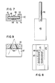
- Pilot fuel flows through the pilot flow connecting tube 14, the fuel lock 15 and is throttled through the orifice 16 (see Figure 2).
- the pilot fuel then flows down the pilot fuel line 17 coaxially located within the main fuel line 20 and through the downstream pipe tee 18 and out through a pilot fuel line 21 to a fuel delivery adapter block 19.
- This adapter block 19 is constructed for positioning on a conventional spark ignition engine where the air stream and fuel is normally inducted into the engine manifold. Pilot fuel flow through the orifice 16 reduces the pressure to a point where the liquid fuel will vaporize. Vaporization takes place as the fuel in the pilot line 17 moves along the length of the main fuel line 20 and heat is transferred from the liquid fuel in the main fuel line into the pilot fuel, all along the run of both lines.
- Main fuel flows out of the upstream pipe tee 13, through the main fuel line 20 into the downstream pipe tee 18 and into the fuel delivery adapter block 19.
- the transfer of heat from the main fuel to the pilot fuel across the wall of the pilot fuel line 17 subcools the main fuel. Heat transfer into the main fuel line 20 from the surroundings may be controlled by proper design of the main fuel conduit.
- the incremental valve 24 consists of a chamber or valve cylinder 25 in the adapter block 19 ( Figure 1) and in the walls of which are drilled a longitudinal series of flow orifices 26 which can be completely covered or progressively uncovered by movement of a piston 27 by applying a force to a piston rod 28 through an actuator mechanism in response to fuel needs.
- the piston 27 is provided with a pair of sealing rings 29, and the piston rod 28 is similarly provided with a seal 31 where the rod extends through an apertured end wall 32 of the cylinder.
- Pressure equalizing ports 33 are provided through the piston 27 to equalize the pressure from the inlet into a rear chamber 34 between the back of the piston 27 and the end wall 32.
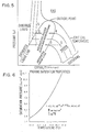
- Any liquid withdrawn from the tank leaves as saturated liquid (point 0). As it flows it can experience heating or cooling and a loss of pressure due to fluid friction. Any transfer of heat into the fuel raises the enthalpy (h) and transforms part of the saturated liquid to saturated vapor (point 6). The flowing fuel moves into the saturation region. This means that vapor bubbles are forming in the flowing line and the fuel is a mixture of liquid vapor, increasing in vapor and decreasing in liquid as it moves down the line.
- the flow is adiabatic (no heat transfer) but drops to a lower pressure and the same velocity then the fluid moves from saturated liquid (point 0) into the saturation region at a constant enthalpy and lower pressure (point 1). Again the fuel is a mixture of liquid and vapor, and increasing in vapor.
- the present invention uses the refrigerating effect of the vaporizing fuel in pilot fuel flow to extract heat from the main flow and maintain it in the liquid phase by overcoming the effects of pressure drop and heat transfer described above.
- throttling Constant enthalpy expansion to a lower pressure from point 0 to point 1
- a lower temperature is generated in the pilot flow.
- the pilot flow draws heat from the main fuel flow, subcooling it from point 0 to point 4 in Figure 5, as the pilot flow continues to vaporize along the path from point 1 to point 2.
- pilot flow sub-cooling An added benefit of this pilot flow sub-cooling is that the pilot flow may be used for idling fuel flow on the engine. Thus, at start-up and during all engine operation, the delivery system is being cooled by the vaporization of the pilot fuel.
- the pressure within the tank 11 remains constant, and as fuel flows out, more liquid vaporizes restoring the saturation pressure.
- the saturation pressure for LPG varies.
- Saturation pressure for propane, for example, varies according to the curve shown in Figure 6.
- the fuel delivery system described here senses the engine fuel requirements and offers a varying impedance to flow at the fuel delivery point such that the fuel tank pressure will induce flow through the system equal to that required.
Landscapes
- Engineering & Computer Science (AREA)
- Chemical & Material Sciences (AREA)
- Combustion & Propulsion (AREA)
- General Engineering & Computer Science (AREA)
- Mechanical Engineering (AREA)
- General Chemical & Material Sciences (AREA)
- Oil, Petroleum & Natural Gas (AREA)
- Chemical Kinetics & Catalysis (AREA)
- Output Control And Ontrol Of Special Type Engine (AREA)
- Electrical Discharge Machining, Electrochemical Machining, And Combined Machining (AREA)
- Jet Pumps And Other Pumps (AREA)
- Lens Barrels (AREA)
- Fuel-Injection Apparatus (AREA)
- Feeding And Controlling Fuel (AREA)
- Spray Control Apparatus (AREA)
Priority Applications (1)
| Application Number | Priority Date | Filing Date | Title |
|---|---|---|---|
| AT81900859T ATE32251T1 (de) | 1980-08-01 | 1980-08-01 | Fluessigbrennstoffsystem. |
Applications Claiming Priority (1)
| Application Number | Priority Date | Filing Date | Title |
|---|---|---|---|
| PCT/US1980/000981 WO1982000492A1 (en) | 1980-08-01 | 1980-08-01 | Liquid fuel system method and apparatus |
Publications (3)
| Publication Number | Publication Date |
|---|---|
| EP0056800A1 EP0056800A1 (en) | 1982-08-04 |
| EP0056800A4 EP0056800A4 (en) | 1983-12-01 |
| EP0056800B1 true EP0056800B1 (en) | 1988-01-27 |
Family
ID=22154458
Family Applications (1)
| Application Number | Title | Priority Date | Filing Date |
|---|---|---|---|
| EP81900859A Expired EP0056800B1 (en) | 1980-08-01 | 1980-08-01 | Liquid fuel system |
Country Status (11)
| Country | Link |
|---|---|
| EP (1) | EP0056800B1 (Direct) |
| JP (1) | JPS57501335A (Direct) |
| AT (1) | ATE32251T1 (Direct) |
| AU (1) | AU7072581A (Direct) |
| CA (1) | CA1195194A (Direct) |
| DE (1) | DE3072071D1 (Direct) |
| DK (1) | DK145982A (Direct) |
| IT (1) | IT1189028B (Direct) |
| MX (1) | MX154378A (Direct) |
| NO (1) | NO154470C (Direct) |
| WO (1) | WO1982000492A1 (Direct) |
Families Citing this family (1)
| Publication number | Priority date | Publication date | Assignee | Title |
|---|---|---|---|---|
| AUPN286095A0 (en) * | 1995-05-09 | 1995-06-01 | Energy Research And Development Corporation, The | Liquid fuel injection system |
Family Cites Families (13)
| Publication number | Priority date | Publication date | Assignee | Title |
|---|---|---|---|---|
| US1905971A (en) * | 1931-07-28 | 1933-04-25 | Shell Dev | Process and apparatus for refrigeration with liquefied fuel gas |
| DE703244C (de) * | 1938-04-30 | 1941-03-04 | I G Farbenindustrie Akt Ges | Vorrichtung zum Betrieb von gemischverdichtenden Brennkraftmaschinen mit gespeicherten, druckverfluessigten Gasen |
| US2359219A (en) * | 1943-03-26 | 1944-09-26 | Green S Fuel Inc | Means for using liquefied petroleum gases for engine fuel |
| US2755074A (en) * | 1952-11-03 | 1956-07-17 | Youngstown Sheet And Tube Co | Carburetors for internal combustion engines |
| US2872911A (en) * | 1954-03-29 | 1959-02-10 | Botto Meccanica Di Prec Srl | Liquefied petroleum gas pressure mixer |
| US3443551A (en) * | 1966-12-07 | 1969-05-13 | Marvin T Laubach | Diesel engine propane accessory |
| US3565201A (en) * | 1969-02-07 | 1971-02-23 | Lng Services | Cryogenic fuel system for land vehicle power plant |
| JPS4720970U (Direct) * | 1971-04-07 | 1972-11-09 | ||
| CH561620A5 (Direct) * | 1972-12-11 | 1975-05-15 | Sulzer Ag | |
| JPS5118314A (ja) * | 1974-06-25 | 1976-02-13 | Jeemusu Betsudofuots Teimoshii | Nainenkikannonenryokyokyusochi |
| US4097562A (en) * | 1975-11-04 | 1978-06-27 | Blakeway Industries Ltd. | Carburetor |
| DE2613401A1 (de) * | 1976-03-29 | 1977-10-06 | Shell Int Research | Verfahren und vorrichtung zum ueberfuehren von fluessiggas aus einem ersten behaelter in einen zweiten |
| WO1979000528A1 (en) * | 1978-01-19 | 1979-08-09 | T Bedford | Internal combustion engine utilising liquefied gaseous fuel |
-
1980
- 1980-08-01 JP JP81501306A patent/JPS57501335A/ja active Pending
- 1980-08-01 DE DE8181900859T patent/DE3072071D1/de not_active Expired
- 1980-08-01 AT AT81900859T patent/ATE32251T1/de not_active IP Right Cessation
- 1980-08-01 EP EP81900859A patent/EP0056800B1/en not_active Expired
- 1980-08-01 AU AU70725/81A patent/AU7072581A/en not_active Abandoned
- 1980-08-01 MX MX188587A patent/MX154378A/es unknown
- 1980-08-01 WO PCT/US1980/000981 patent/WO1982000492A1/en not_active Ceased
-
1981
- 1981-08-03 CA CA000383093A patent/CA1195194A/en not_active Expired
- 1981-08-03 IT IT23327/81A patent/IT1189028B/it active
-
1982
- 1982-03-30 NO NO82821060A patent/NO154470C/no unknown
- 1982-03-31 DK DK145982A patent/DK145982A/da not_active IP Right Cessation
Also Published As
| Publication number | Publication date |
|---|---|
| WO1982000492A1 (en) | 1982-02-18 |
| DK145982A (da) | 1982-03-31 |
| DE3072071D1 (en) | 1988-03-03 |
| EP0056800A1 (en) | 1982-08-04 |
| CA1195194A (en) | 1985-10-15 |
| AU7072581A (en) | 1982-03-02 |
| EP0056800A4 (en) | 1983-12-01 |
| ATE32251T1 (de) | 1988-02-15 |
| NO154470C (no) | 1986-09-24 |
| IT8123327A1 (it) | 1983-02-03 |
| NO154470B (no) | 1986-06-16 |
| MX154378A (es) | 1987-08-04 |
| IT8123327A0 (it) | 1981-08-03 |
| JPS57501335A (Direct) | 1982-07-29 |
| NO821060L (no) | 1982-03-30 |
| IT1189028B (it) | 1988-01-28 |
Similar Documents
| Publication | Publication Date | Title |
|---|---|---|
| US4503832A (en) | Liquid fuel system method and apparatus | |
| US4430978A (en) | Direct liquid injection of liquid petroleum gas | |
| JP4101794B2 (ja) | タービンエンジン燃料噴射器 | |
| US5076244A (en) | Fuel injector | |
| US4421280A (en) | Fuel injector | |
| Jin et al. | Numerical investigation of flame appearance and heat flux and in a deep-throttling variable thrust rocket engine | |
| US4430860A (en) | Supercharged internal combustion engines, inter alia diesel engines | |
| GB2342692A (en) | Waste heat rejection system. | |
| RU2445504C2 (ru) | Устройство (варианты) и способ впрыска и подачи топлива для поршневого двигателя | |
| CS209854B2 (en) | Driving facility | |
| US4545356A (en) | Liquified petroleum gas carburetor | |
| US4651682A (en) | Liquid fuel system method and apparatus | |
| US4515134A (en) | Molecular diffuser assembly | |
| EP0056800B1 (en) | Liquid fuel system | |
| Wang et al. | Influence of fuel temperature on atomization performance of pressure-swirl atomizers | |
| CA1334916C (en) | Vaporiser nozzle | |
| GB1102572A (en) | Jet propulsion engines | |
| US5860407A (en) | Gaseous fuel control system for engines | |
| CA2505123C (en) | Fuel system for premix burner of a direct-fired steam generator | |
| GB2042076A (en) | IC engine surface carburetting apparatus | |
| JPS59200048A (ja) | 液化ガスを噴射するための装置 | |
| Xiaobin et al. | Studies on the combustion efficiency of liquid fuel rockets with variable thrust | |
| Quandt | Water droplet evaporation in air during compression in a gas turbine engine | |
| Nightingale | Mixture preparation for spark-ignition engines | |
| JPS6143260A (ja) | 可変ベンチユリ型気化器 |
Legal Events
| Date | Code | Title | Description |
|---|---|---|---|
| PUAI | Public reference made under article 153(3) epc to a published international application that has entered the european phase |
Free format text: ORIGINAL CODE: 0009012 |
|
| 17P | Request for examination filed |
Effective date: 19820331 |
|
| AK | Designated contracting states |
Kind code of ref document: A1 Designated state(s): AT CH DE FR GB LU NL SE |
|
| GRAA | (expected) grant |
Free format text: ORIGINAL CODE: 0009210 |
|
| AK | Designated contracting states |
Kind code of ref document: B1 Designated state(s): AT CH DE FR GB LI LU NL SE |
|
| PG25 | Lapsed in a contracting state [announced via postgrant information from national office to epo] |
Ref country code: LI Effective date: 19880127 Ref country code: CH Effective date: 19880127 Ref country code: AT Effective date: 19880127 |
|
| REF | Corresponds to: |
Ref document number: 32251 Country of ref document: AT Date of ref document: 19880215 Kind code of ref document: T |
|
| PG25 | Lapsed in a contracting state [announced via postgrant information from national office to epo] |
Ref country code: SE Effective date: 19880131 |
|
| REF | Corresponds to: |
Ref document number: 3072071 Country of ref document: DE Date of ref document: 19880303 |
|
| REG | Reference to a national code |
Ref country code: CH Ref legal event code: PL |
|
| ET | Fr: translation filed | ||
| PG25 | Lapsed in a contracting state [announced via postgrant information from national office to epo] |
Ref country code: LU Free format text: LAPSE BECAUSE OF NON-PAYMENT OF DUE FEES Effective date: 19880831 |
|
| PLBE | No opposition filed within time limit |
Free format text: ORIGINAL CODE: 0009261 |
|
| STAA | Information on the status of an ep patent application or granted ep patent |
Free format text: STATUS: NO OPPOSITION FILED WITHIN TIME LIMIT |
|
| 26N | No opposition filed | ||
| PG25 | Lapsed in a contracting state [announced via postgrant information from national office to epo] |
Ref country code: NL Effective date: 19890301 |
|
| NLV4 | Nl: lapsed or anulled due to non-payment of the annual fee | ||
| PG25 | Lapsed in a contracting state [announced via postgrant information from national office to epo] |
Ref country code: DE Effective date: 19890503 |
|
| PGFP | Annual fee paid to national office [announced via postgrant information from national office to epo] |
Ref country code: GB Payment date: 19900131 Year of fee payment: 10 |
|
| PGFP | Annual fee paid to national office [announced via postgrant information from national office to epo] |
Ref country code: FR Payment date: 19900228 Year of fee payment: 10 |
|
| PG25 | Lapsed in a contracting state [announced via postgrant information from national office to epo] |
Ref country code: GB Effective date: 19900801 |
|
| GBPC | Gb: european patent ceased through non-payment of renewal fee | ||
| PG25 | Lapsed in a contracting state [announced via postgrant information from national office to epo] |
Ref country code: FR Effective date: 19910430 |
|
| REG | Reference to a national code |
Ref country code: FR Ref legal event code: ST |