EP0056744B1 - Wärmetauscher mit Bündeln gerader oder wellenförmiger Rohre, besonders an Rohrunterstützungssystemen, und Verfahren zur Verwirklichung solcher Systeme - Google Patents
Wärmetauscher mit Bündeln gerader oder wellenförmiger Rohre, besonders an Rohrunterstützungssystemen, und Verfahren zur Verwirklichung solcher Systeme Download PDFInfo
- Publication number
- EP0056744B1 EP0056744B1 EP82400008A EP82400008A EP0056744B1 EP 0056744 B1 EP0056744 B1 EP 0056744B1 EP 82400008 A EP82400008 A EP 82400008A EP 82400008 A EP82400008 A EP 82400008A EP 0056744 B1 EP0056744 B1 EP 0056744B1
- Authority
- EP
- European Patent Office
- Prior art keywords
- tubes
- supporting
- radial
- central tube
- welded
- Prior art date
- Legal status (The legal status is an assumption and is not a legal conclusion. Google has not performed a legal analysis and makes no representation as to the accuracy of the status listed.)
- Expired
Links
- 238000000034 method Methods 0.000 title claims description 4
- 210000001520 comb Anatomy 0.000 claims description 20
- 239000012530 fluid Substances 0.000 claims description 8
- XEEYBQQBJWHFJM-UHFFFAOYSA-N Iron Chemical compound [Fe] XEEYBQQBJWHFJM-UHFFFAOYSA-N 0.000 claims description 6
- 238000003466 welding Methods 0.000 claims description 6
- 229910052742 iron Inorganic materials 0.000 claims description 3
- 238000004519 manufacturing process Methods 0.000 claims description 3
- 238000003491 array Methods 0.000 claims 1
- 230000000903 blocking effect Effects 0.000 claims 1
- 230000001413 cellular effect Effects 0.000 description 4
- 238000009826 distribution Methods 0.000 description 3
- 230000002093 peripheral effect Effects 0.000 description 3
- 230000005540 biological transmission Effects 0.000 description 2
- 230000010339 dilation Effects 0.000 description 2
- 238000009434 installation Methods 0.000 description 2
- 230000001174 ascending effect Effects 0.000 description 1
- 239000000470 constituent Substances 0.000 description 1
- 230000006866 deterioration Effects 0.000 description 1
- 238000010586 diagram Methods 0.000 description 1
- 238000006073 displacement reaction Methods 0.000 description 1
- 230000000694 effects Effects 0.000 description 1
- 235000000396 iron Nutrition 0.000 description 1
- 230000014759 maintenance of location Effects 0.000 description 1
Images


Classifications
-
- F—MECHANICAL ENGINEERING; LIGHTING; HEATING; WEAPONS; BLASTING
- F28—HEAT EXCHANGE IN GENERAL
- F28F—DETAILS OF HEAT-EXCHANGE AND HEAT-TRANSFER APPARATUS, OF GENERAL APPLICATION
- F28F9/00—Casings; Header boxes; Auxiliary supports for elements; Auxiliary members within casings
- F28F9/22—Arrangements for directing heat-exchange media into successive compartments, e.g. arrangements of guide plates
-
- F—MECHANICAL ENGINEERING; LIGHTING; HEATING; WEAPONS; BLASTING
- F28—HEAT EXCHANGE IN GENERAL
- F28D—HEAT-EXCHANGE APPARATUS, NOT PROVIDED FOR IN ANOTHER SUBCLASS, IN WHICH THE HEAT-EXCHANGE MEDIA DO NOT COME INTO DIRECT CONTACT
- F28D7/00—Heat-exchange apparatus having stationary tubular conduit assemblies for both heat-exchange media, the media being in contact with different sides of a conduit wall
- F28D7/08—Heat-exchange apparatus having stationary tubular conduit assemblies for both heat-exchange media, the media being in contact with different sides of a conduit wall the conduits being otherwise bent, e.g. in a serpentine or zig-zag
-
- F—MECHANICAL ENGINEERING; LIGHTING; HEATING; WEAPONS; BLASTING
- F28—HEAT EXCHANGE IN GENERAL
- F28F—DETAILS OF HEAT-EXCHANGE AND HEAT-TRANSFER APPARATUS, OF GENERAL APPLICATION
- F28F9/00—Casings; Header boxes; Auxiliary supports for elements; Auxiliary members within casings
- F28F9/007—Auxiliary supports for elements
- F28F9/013—Auxiliary supports for elements for tubes or tube-assemblies
- F28F9/0133—Auxiliary supports for elements for tubes or tube-assemblies formed by concentric strips
-
- Y—GENERAL TAGGING OF NEW TECHNOLOGICAL DEVELOPMENTS; GENERAL TAGGING OF CROSS-SECTIONAL TECHNOLOGIES SPANNING OVER SEVERAL SECTIONS OF THE IPC; TECHNICAL SUBJECTS COVERED BY FORMER USPC CROSS-REFERENCE ART COLLECTIONS [XRACs] AND DIGESTS
- Y10—TECHNICAL SUBJECTS COVERED BY FORMER USPC
- Y10S—TECHNICAL SUBJECTS COVERED BY FORMER USPC CROSS-REFERENCE ART COLLECTIONS [XRACs] AND DIGESTS
- Y10S165/00—Heat exchange
- Y10S165/355—Heat exchange having separate flow passage for two distinct fluids
- Y10S165/40—Shell enclosed conduit assembly
- Y10S165/401—Shell enclosed conduit assembly including tube support or shell-side flow director
- Y10S165/416—Extending transverse of shell, e.g. fin, baffle
- Y10S165/417—Extending transverse of shell, e.g. fin, baffle including spacer or support for transverse tube support or shell-side flow director
- Y10S165/419—Spacer or support connected to shell
Definitions
- the present invention relates to a heat exchanger, and it relates to improvements in heat exchangers, in particular applicable to a steam generator, with straight tubes, preferably corrugated tubes, arranged in vertical sheets, parallel and maintained at certain levels.
- axial by concentric support systems, each of which is constituted by a circular strip with alternating trapezoidal cells, welded to a support strip and closed, after fitting the tubes, by a closure strip to which the support strip is welded of the following support system in the radial direction of the grille.
- the tubes are arranged so that the planes containing their undulations are substantially tangent to the circles of the associated tubular bundles provided between the shell and a central tube of the heat exchanger.
- the corrugated tubes contract or expand, more particularly at the level of the corrugations whose arrows vary, which results in a tangential force which is exerted on the various support systems in the cells of which the corrugated parts of the tubes are trapped. And, in the same sector of concentric support systems located at the same level, the peripheral displacement of the different portions of the support systems of this sector increases from the center towards the grille.
- At least some of the support systems, located at the same level, are independent of neighboring support systems and form groups of support systems, _and ue _bras radial are provided for the apptn said independent support systems, in the space between the grille and the central tube.
- all the mobile support systems of the same level are independent of each other, and radial arms are provided on both sides. on the other of all support systems of the same level.
- each radial arm is constituted by two flat bars welded on edge, with a certain spacing between them.
- the first can be welded to the grille and the second to said central tube, which improves the retention of support systems.
- the combs arranged at a given level are angularly offset relative to the combs arranged at the next level and at the previous level, the angular offset being such that the projection on a horizontal plane of two combs located at two successive levels is a ring s' extending over 360 °.
- the comb of each level extends in an arc of 300 °, but it can also extend over 180 °, or less. It is understood that combs extending over such arcs are formed by pieces of coextensive combs and welded together.
- a heat exchanger and more particularly a steam generator, is a large device, and for convenience, the radiator grille is placed horizontally on electric turners to allow the placement of the bundles and support by sectors of 60 ° or possibly 120 °.
- the invention proposes a method which consists in that the radial arms welded to the inner face of the grille or to the ring which is adjacent to it, are supported using of stiffening flat bars welded at their ends to the bottom plates in which the ends of the tubes are held and provided with openings for the passage of the free ends of the radial arms; after installation of the tube bundle and the support systems, said stiffening flat bars are dismantled and the central tube is put in place and is welded to said radial arms by openings which it comprises, said central tube possibly being able to be produced in the calender, by assembling and welding individual wall elements.
- FIG. 1 there is shown schematically the general appearance of a corrugated tube, suitable for implementing the invention.
- This tube is mounted by its two straight ends 1 and 2 in the plates 3 and 4 usually provided at the base of the upper and lower domes that comprise a steam generator or more generally a heat exchanger. Between these straight ends 1 and 2, the tube has undulations of which only two have been shown at 5 and 6. These undulations 5 and 6 are situated on the same side of a straight portion 7 which connects two successive undulations and which is aligned with the ends 1 and 2, and they are connected to it by curved portions 8 and 9, while they are connected respectively to the straight ends 1 and 2 by the curved portions 9 and 10.
- the corrugated tubes are arranged so that the plane containing the axis of the corrugations and that of the straight portions lies substantially in the plane tangential to the circle of the circumferential alignment of the tubes of the relevant circular row of the bundle.
- the reference 5 designates the corresponding corrugation of FIG. 1, and there is indicated the arrow f of the ripple at rest.
- the arrow f increases and takes the value f ', and it goes from 10 to 10'.
- the concentric support systems form between the calender and the central tube a whole in one piece and the portions of the concentric support systems and subtending a same angle in the center, undergo, for the same temperature, peripheral dilations which grow from the center to the grille.
- the invention proposes the arrangement of FIG. 3.
- a ring 19 is placed near the inner face 18 of the calender 11 in a vertical position.
- annular support band 20 Against the inner face of the ring is placed an annular support band 20 and to this is welded a honeycomb band 21 as described in FR-A-2 420 735, and in the cells of which the tubes are placed such as that designated by 5, and held in place by a closure strip 22 welded to the cellular strip 21.
- Concentric support systems have thus been produced, independent of each other, so that the circumferential expansion of one of the systems is independent of the neighboring system or systems.
- each radial arm 14 and 14 ′ will be constituted by two flat bars such as those designated by 14 and 14 ′ and which will be arranged on either side of the radial row of tubes 5 ,, 5 '... 5n.
- Fig. 3A shows in perspective two pieces of two successive support systems between the radial arms and arranged at a movable level.
- the external support system consists of the support strip 20 to which is welded, by welding points such as that indicated by S, the cellular strip 21 against which the closure strip 22 is freely applied.
- the internal support system is constituted in the same way by the support strip 20 ', by the honeycomb strip 21' and by the closure strip 22 ' , with the same weld point S, the assembly of the two support systems being disposed freely between the radial arms 14 and 14 '. And, according to the invention, no welding is provided between the two support systems. If desired, a welding point can be provided between 21 and 22 and between 21 'and 22'.
- Fig. 3B shows an arrangement identical to that of FIG. 3A, but for a "fixed level", with this double difference that only the radial arm 14 and a weld S "are provided there between the arm 14 and the closure strip 22 ', it being understood that such weld S "may be provided between the arm 14 and the closure strip of each support system such as that designated by 22,22 '.
- the combs 29, 29 '... 29n are associated respectively with the rows of the tubes 5, 5 ' ... 5n and are laid flat on the alveolar strips 21, 21 '... 21 n and held in place place by welding to the support strips 20, 20 ' ... 20n in a position such that the teeth of each comb 29, 29' ... 29n pass between the tubes held by the respective cellular strips 21, 2T ... 21 not.
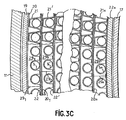
- Each of the combs 29, 29 ' ... 29n is in fact constituted by partial and coextensive combs, welded together by weld lines such as those indicated in fig. 3C par 29 1 , 29 2 ... 29n to extend over an arc whose value depends on the trajectory that one wishes to print on said fluid, and all of these combs constitute deflectors whose arrangement of a level of support systems to another will be explained using fig. 3D.
- combs 29a, 29a ′ , 29a ’ are provided at the various mobile and fixed levels, represented schematically in the form of rings extending at an angle a, each of these rings forming deflectors by means of combs as shown in Fig. 3C
- the angle a is equal to 300 ° and the path impressed on the fluid from one level to another is tilted as much as possible on the axis of the device so as to give a maximum heat transfer coefficient at the level of the tubes not shown in this figure.
- the angle a can also be equal to 240 °, but in all cases, the arrangement of the rings or deflectors is symmetrical between two successive stages, and in the case of this arrangement, the fluid coming from a lower level in direction D is distributed at the next level in directions D and D z .
- the arrangement of the radial arms 14 and 14 ' of FIG. 3, on either side of all of the support systems provided at a given level so that a support system is independent of neighboring support systems, is particularly advantageous for mounting the tubular bundles and the support in the radiator grille placed horizontally, in particular on electric tackers as shown in figs. 4 and 5 in which only two tackers 23 and 24 have been shown tees, the presence of these turners allowing the mounting of the tube bundle in sectors of 60 °, for example delimited by the pairs of radial arms 14-14,14 ' -14' ... 14n-14n.
- the inner ends 15, 15 ′ of the radial arms such as 14, 14 ′ are mounted in openings made in temporary flat irons 25, 26 fixed to the plates 3 and 4 and removed for the placement of the inner cylinder 17 (fig. 3).
- the flat bars 25, 26 are removed and the central tube 27 is put in place as shown in FIG. 6.
- Each deflector 29, 29, ... 29 n can in this case extend over an arc of 306 ° and form a ring whose radial thickness is less than the radial distance between the grille and the central tube, with the particularity that successive rings are arranged alternately on the side of the radiator grille and on the side of the central tube to impart an undulating trajectory to the ascending fluid. It will be noted that the radial thicknesses of the successive rings are different from each other, while the radial thicknesses of the rings which have the same arrangement are equal to each other.
- Fig. 7 shows the sketch used to determine this distribution in the case where we adopt the assembly by secterus of 60 °.
Landscapes
- Engineering & Computer Science (AREA)
- Physics & Mathematics (AREA)
- Thermal Sciences (AREA)
- Mechanical Engineering (AREA)
- General Engineering & Computer Science (AREA)
- Heat-Exchange Devices With Radiators And Conduit Assemblies (AREA)
Claims (10)
Priority Applications (1)
| Application Number | Priority Date | Filing Date | Title |
|---|---|---|---|
| AT82400008T ATE5614T1 (de) | 1981-01-08 | 1982-01-05 | Waermetauscher mit buendeln gerader oder wellenfoermiger rohre, besonders an rohrunterstuetzungssystemen, und verfahren zur verwirklichung solcher systeme. |
Applications Claiming Priority (4)
| Application Number | Priority Date | Filing Date | Title |
|---|---|---|---|
| FR8100212A FR2497566B1 (fr) | 1981-01-08 | 1981-01-08 | Perfectionnement aux echangeurs de chaleur |
| FR8100212 | 1981-01-08 | ||
| FR8102993 | 1981-02-16 | ||
| FR8102993A FR2500144B1 (fr) | 1981-02-16 | 1981-02-16 | Perfectionnement aux echangeurs de chaleur a faisceaux de tubes droits ou ondules, notamment aux systemes de supportage des tubes et procede de realisation de ces systemes de supportage |
Publications (3)
| Publication Number | Publication Date |
|---|---|
| EP0056744A2 EP0056744A2 (de) | 1982-07-28 |
| EP0056744A3 EP0056744A3 (en) | 1982-08-04 |
| EP0056744B1 true EP0056744B1 (de) | 1983-12-14 |
Family
ID=26222174
Family Applications (1)
| Application Number | Title | Priority Date | Filing Date |
|---|---|---|---|
| EP82400008A Expired EP0056744B1 (de) | 1981-01-08 | 1982-01-05 | Wärmetauscher mit Bündeln gerader oder wellenförmiger Rohre, besonders an Rohrunterstützungssystemen, und Verfahren zur Verwirklichung solcher Systeme |
Country Status (5)
| Country | Link |
|---|---|
| US (1) | US4573528A (de) |
| EP (1) | EP0056744B1 (de) |
| BR (1) | BR8200057A (de) |
| CA (1) | CA1208995A (de) |
| DE (1) | DE3260017D1 (de) |
Families Citing this family (5)
| Publication number | Priority date | Publication date | Assignee | Title |
|---|---|---|---|---|
| DE3904140C1 (de) * | 1989-02-11 | 1990-04-05 | Mtu Muenchen Gmbh | |
| US5311271A (en) * | 1992-01-21 | 1994-05-10 | Dme/Golf, Inc. | Golf course range finder |
| US6702190B1 (en) | 2001-07-02 | 2004-03-09 | Arvin Technologies, Inc. | Heat transfer system for a vehicle |
| US7152665B2 (en) * | 2003-05-08 | 2006-12-26 | Kabushiki Kaisha Toyota Jidoshokki | Pressure tank |
| EP2960614B1 (de) * | 2013-04-25 | 2018-03-14 | Mitsubishi Heavy Industries, Ltd. | Vorrichtung und verfahren zur schwingungsunterdrückung eines wärmeübertragungsrohrs und dampferzeuger |
Family Cites Families (29)
| Publication number | Priority date | Publication date | Assignee | Title |
|---|---|---|---|---|
| FR65106E (fr) * | 1953-12-31 | 1956-01-26 | Chausson Usines Sa | échangeur thermique en particulier pour aéronefs et applications analogues |
| US2942855A (en) * | 1955-08-17 | 1960-06-28 | Rekuperator K G Dr Ing Schack | Recuperator |
| US2980404A (en) * | 1957-11-07 | 1961-04-18 | Union Carbide Corp | Heat exchange device |
| US2978226A (en) * | 1958-12-18 | 1961-04-04 | Gen Electric | Tube type heat exchanger |
| US3134432A (en) * | 1962-06-20 | 1964-05-26 | United Aircraft Corp | Heat exchanger |
| DE1303351B (de) * | 1963-04-01 | Hitachi Ltd | ||
| FR1364849A (fr) * | 1963-06-07 | 1964-06-26 | Motala Verkstad Ab | Dispositif d'étayage pour tubes, tiges ou autres dans des générateurs de vapeur, échangeurs thermiques tubulaires ou autres |
| US3336974A (en) * | 1965-05-05 | 1967-08-22 | United Aircraft Corp | Serpentine tube boiler |
| FR1491534A (fr) * | 1966-07-01 | 1967-08-11 | Ct D Etudes Pour L Ind Pharma | Réfrigérant perfectionné |
| US3420297A (en) * | 1967-04-25 | 1969-01-07 | Combustion Eng | Heat exchanger tube support and spacing structure |
| GB1280662A (en) * | 1969-01-28 | 1972-07-05 | Atomic Energy Authority Uk | Improvements in or relating to tubular heat exchangers |
| FR2077865A1 (en) * | 1970-02-19 | 1971-11-05 | Trepaud Georges | Cylindrical heat exchanger - with twin helical passages surrounding central tube bundle |
| GB1306864A (en) * | 1970-08-25 | 1973-02-14 | Head Wrightson & Co Ltd | Tubular heat exchangers |
| US3683866A (en) * | 1970-11-20 | 1972-08-15 | Combustion Eng | Superheating steam generator |
| DE2100664A1 (de) * | 1971-01-08 | 1972-07-20 | The Batteile Development Corp., Columbus, Ohio (V.StA.) | Verdampfer für Kälteanlagen |
| FR2172799A1 (en) * | 1972-02-22 | 1973-10-05 | Trepaud Georges | Nuclear reactor heat exchanger - with central shaft giving access for tube installation and repair |
| US3989105A (en) * | 1972-02-22 | 1976-11-02 | Georges Trepaud | Heat exchanger |
| US3782455A (en) * | 1972-05-01 | 1974-01-01 | Atomic Energy Commission | Heat exchanger tube mounts |
| FR2266866A2 (en) * | 1974-04-03 | 1975-10-31 | Trepaud Georges | Heat exchanger with tube bundle - having tubes each shaped in wave-form and having supports preventing axial rotation |
| FR2293684A2 (fr) * | 1974-12-05 | 1976-07-02 | Trepaud Georges | Echangeur de chaleur a faisceau tubulaire |
| DE2613745A1 (de) * | 1976-03-31 | 1977-10-06 | Linde Ag | Waermetauscher |
| FR2355191A1 (fr) * | 1976-06-16 | 1978-01-13 | Creusot Loire | Dispositif de maintien d'une nappe de tubes a l'interieur d'une enceinte |
| US4154295A (en) * | 1977-02-02 | 1979-05-15 | General Atomic Company | Heat exchanger tube support assembly |
| FR2420735A2 (fr) * | 1978-03-24 | 1979-10-19 | Trepaud Georges | Echangeur de chaleur a faisceau tubulaire |
| US4210202A (en) * | 1978-03-30 | 1980-07-01 | Ecolaire Incorporated | Support for heat exchange tubes |
| US4253516A (en) * | 1978-06-22 | 1981-03-03 | Westinghouse Electric Corp. | Modular heat exchanger |
| FR2459441A1 (fr) * | 1979-06-19 | 1981-01-09 | Stein Industrie | Grille support pour faisceau de tubes d'echange de chaleur |
| FR2461221A1 (fr) * | 1979-07-11 | 1981-01-30 | Stein Industrie | Dispositif de support des tubes d'un faisceau tubulaire |
| US4325171A (en) * | 1979-10-15 | 1982-04-20 | Econo-Therm Energy Systems Corporation | Means and method for sealing heat exchanger walls |
-
1981
- 1981-12-29 US US06/335,537 patent/US4573528A/en not_active Expired - Fee Related
-
1982
- 1982-01-05 CA CA000393584A patent/CA1208995A/en not_active Expired
- 1982-01-05 EP EP82400008A patent/EP0056744B1/de not_active Expired
- 1982-01-05 DE DE8282400008T patent/DE3260017D1/de not_active Expired
- 1982-01-07 BR BR8200057A patent/BR8200057A/pt unknown
Also Published As
| Publication number | Publication date |
|---|---|
| DE3260017D1 (en) | 1984-01-19 |
| CA1208995A (en) | 1986-08-05 |
| US4573528A (en) | 1986-03-04 |
| EP0056744A2 (de) | 1982-07-28 |
| EP0056744A3 (en) | 1982-08-04 |
| BR8200057A (pt) | 1982-10-26 |
Similar Documents
| Publication | Publication Date | Title |
|---|---|---|
| EP0186592B1 (de) | Plattenwärmetauscher | |
| EP0596786B1 (de) | Mit Fahnen versehenes Abstandshaltergitter für Kernbrennstoffbündel | |
| FR2824895A1 (fr) | Ailette ondulee a persiennes pour echangeur de chaleur a plaques, et echangeur a plaques muni de telles ailettes | |
| JPS6023280B2 (ja) | 容器内におけるパイプ列保持装置 | |
| FR2465297A1 (fr) | Grille d'espacement pour elements combustibles de reacteurs nucleaires | |
| FR2707382A1 (fr) | Echangeur de chaleur comportant un faisceau de tubes cintrés en U et des barres antivibratoires entre les parties cintrées des tubes. | |
| EP0056744B1 (de) | Wärmetauscher mit Bündeln gerader oder wellenförmiger Rohre, besonders an Rohrunterstützungssystemen, und Verfahren zur Verwirklichung solcher Systeme | |
| FR2848292A1 (fr) | Plaque d'un echangeur thermique et echangeur thermique a plaques | |
| EP0078728B1 (de) | Schwingungsdämpfende Halterung für ein Rohrbündel, insbesondere für einen Dampferzeuger, und Verfahren zum Montieren dieser Halterung | |
| CH622091A5 (de) | ||
| EP0544579B1 (de) | Wärmetauscher mit U-Rohren und Anti-Auftriebshalterung | |
| FR2595981A1 (fr) | Empilement de plaques en matiere thermoplastique soudable | |
| WO2002001135A9 (fr) | Echangeur spirale multiecartement | |
| FR2500144A1 (fr) | Perfectionnement aux echangeurs de chaleur a faisceaux de tubes droits ou ondules, notamment aux systemes de supportage des tubes et procede de realisation de ces systemes de supportage | |
| EP0553340B1 (de) | Plattenwärmetauscher | |
| CH615525A5 (de) | ||
| WO2018002544A2 (fr) | Échangeur de chaleur mécanique et procédé de fabrication associe | |
| FR2538889A1 (fr) | Echangeur de chaleur a chambres plates ainsi que procede et machine pour la fabrication de cet echangeur | |
| FR1465845A (fr) | Paroi tubulaire étanche aux gaz pour chauffage de fluides et procédé de fabrication | |
| EP0099835A2 (de) | Wärmetauscher mit Modulstruktur | |
| FR2462767A2 (fr) | Chassis d'entreposage d'elements combustibles de reacteur nucleaire | |
| BE886695A (fr) | Perfectionnements aux capuchons de cheminees | |
| FR3086742A1 (fr) | Plaque pour un echangeur de chaleur a plaques | |
| CH460831A (fr) | Echangeur de chaleur | |
| FR2497566A1 (fr) | Perfectionnement aux echangeurs de chaleur |
Legal Events
| Date | Code | Title | Description |
|---|---|---|---|
| PUAI | Public reference made under article 153(3) epc to a published international application that has entered the european phase |
Free format text: ORIGINAL CODE: 0009012 |
|
| PUAL | Search report despatched |
Free format text: ORIGINAL CODE: 0009013 |
|
| AK | Designated contracting states |
Designated state(s): AT BE CH DE GB IT LU NL SE |
|
| AK | Designated contracting states |
Designated state(s): AT BE CH DE GB IT LU NL SE |
|
| 17P | Request for examination filed |
Effective date: 19820805 |
|
| ITF | It: translation for a ep patent filed | ||
| GRAA | (expected) grant |
Free format text: ORIGINAL CODE: 0009210 |
|
| AK | Designated contracting states |
Designated state(s): AT BE CH DE GB IT LI LU NL SE |
|
| PGFP | Annual fee paid to national office [announced via postgrant information from national office to epo] |
Ref country code: LU Payment date: 19831214 Year of fee payment: 3 |
|
| REF | Corresponds to: |
Ref document number: 5614 Country of ref document: AT Date of ref document: 19831215 Kind code of ref document: T |
|
| PGFP | Annual fee paid to national office [announced via postgrant information from national office to epo] |
Ref country code: CH Payment date: 19840106 Year of fee payment: 3 |
|
| REF | Corresponds to: |
Ref document number: 3260017 Country of ref document: DE Date of ref document: 19840119 |
|
| PG25 | Lapsed in a contracting state [announced via postgrant information from national office to epo] |
Ref country code: LU Free format text: LAPSE BECAUSE OF NON-PAYMENT OF DUE FEES Effective date: 19840131 |
|
| PLBE | No opposition filed within time limit |
Free format text: ORIGINAL CODE: 0009261 |
|
| STAA | Information on the status of an ep patent application or granted ep patent |
Free format text: STATUS: NO OPPOSITION FILED WITHIN TIME LIMIT |
|
| PGFP | Annual fee paid to national office [announced via postgrant information from national office to epo] |
Ref country code: DE Payment date: 19841029 Year of fee payment: 4 |
|
| 26N | No opposition filed | ||
| PGFP | Annual fee paid to national office [announced via postgrant information from national office to epo] |
Ref country code: SE Payment date: 19841231 Year of fee payment: 4 Ref country code: BE Payment date: 19841231 Year of fee payment: 4 |
|
| PGFP | Annual fee paid to national office [announced via postgrant information from national office to epo] |
Ref country code: AT Payment date: 19851126 Year of fee payment: 5 |
|
| PGFP | Annual fee paid to national office [announced via postgrant information from national office to epo] |
Ref country code: NL Payment date: 19860131 Year of fee payment: 5 |
|
| PG25 | Lapsed in a contracting state [announced via postgrant information from national office to epo] |
Ref country code: AT Effective date: 19870105 |
|
| PG25 | Lapsed in a contracting state [announced via postgrant information from national office to epo] |
Ref country code: LI Effective date: 19870131 Ref country code: CH Effective date: 19870131 |
|
| BERE | Be: lapsed |
Owner name: TREPAUD GEORGES Effective date: 19870131 |
|
| PG25 | Lapsed in a contracting state [announced via postgrant information from national office to epo] |
Ref country code: NL Effective date: 19870801 |
|
| GBPC | Gb: european patent ceased through non-payment of renewal fee | ||
| NLV4 | Nl: lapsed or anulled due to non-payment of the annual fee | ||
| REG | Reference to a national code |
Ref country code: CH Ref legal event code: PL |
|
| PG25 | Lapsed in a contracting state [announced via postgrant information from national office to epo] |
Ref country code: DE Effective date: 19871001 |
|
| PG25 | Lapsed in a contracting state [announced via postgrant information from national office to epo] |
Ref country code: SE Effective date: 19880106 |
|
| PG25 | Lapsed in a contracting state [announced via postgrant information from national office to epo] |
Ref country code: GB Effective date: 19881121 |
|
| PG25 | Lapsed in a contracting state [announced via postgrant information from national office to epo] |
Ref country code: BE Effective date: 19890131 |
|
| EUG | Se: european patent has lapsed |
Ref document number: 82400008.7 Effective date: 19880913 |