EP0056744B1 - Heat exchangers with bundles of straight or undulating tubes, especially on systems of supporting tubes, and method of realising such systems - Google Patents
Heat exchangers with bundles of straight or undulating tubes, especially on systems of supporting tubes, and method of realising such systems Download PDFInfo
- Publication number
- EP0056744B1 EP0056744B1 EP82400008A EP82400008A EP0056744B1 EP 0056744 B1 EP0056744 B1 EP 0056744B1 EP 82400008 A EP82400008 A EP 82400008A EP 82400008 A EP82400008 A EP 82400008A EP 0056744 B1 EP0056744 B1 EP 0056744B1
- Authority
- EP
- European Patent Office
- Prior art keywords
- tubes
- supporting
- radial
- central tube
- welded
- Prior art date
- Legal status (The legal status is an assumption and is not a legal conclusion. Google has not performed a legal analysis and makes no representation as to the accuracy of the status listed.)
- Expired
Links
Images


Classifications
-
- F—MECHANICAL ENGINEERING; LIGHTING; HEATING; WEAPONS; BLASTING
- F28—HEAT EXCHANGE IN GENERAL
- F28F—DETAILS OF HEAT-EXCHANGE AND HEAT-TRANSFER APPARATUS, OF GENERAL APPLICATION
- F28F9/00—Casings; Header boxes; Auxiliary supports for elements; Auxiliary members within casings
- F28F9/22—Arrangements for directing heat-exchange media into successive compartments, e.g. arrangements of guide plates
-
- F—MECHANICAL ENGINEERING; LIGHTING; HEATING; WEAPONS; BLASTING
- F28—HEAT EXCHANGE IN GENERAL
- F28D—HEAT-EXCHANGE APPARATUS, NOT PROVIDED FOR IN ANOTHER SUBCLASS, IN WHICH THE HEAT-EXCHANGE MEDIA DO NOT COME INTO DIRECT CONTACT
- F28D7/00—Heat-exchange apparatus having stationary tubular conduit assemblies for both heat-exchange media, the media being in contact with different sides of a conduit wall
- F28D7/08—Heat-exchange apparatus having stationary tubular conduit assemblies for both heat-exchange media, the media being in contact with different sides of a conduit wall the conduits being otherwise bent, e.g. in a serpentine or zig-zag
-
- F—MECHANICAL ENGINEERING; LIGHTING; HEATING; WEAPONS; BLASTING
- F28—HEAT EXCHANGE IN GENERAL
- F28F—DETAILS OF HEAT-EXCHANGE AND HEAT-TRANSFER APPARATUS, OF GENERAL APPLICATION
- F28F9/00—Casings; Header boxes; Auxiliary supports for elements; Auxiliary members within casings
- F28F9/007—Auxiliary supports for elements
- F28F9/013—Auxiliary supports for elements for tubes or tube-assemblies
- F28F9/0133—Auxiliary supports for elements for tubes or tube-assemblies formed by concentric strips
-
- Y—GENERAL TAGGING OF NEW TECHNOLOGICAL DEVELOPMENTS; GENERAL TAGGING OF CROSS-SECTIONAL TECHNOLOGIES SPANNING OVER SEVERAL SECTIONS OF THE IPC; TECHNICAL SUBJECTS COVERED BY FORMER USPC CROSS-REFERENCE ART COLLECTIONS [XRACs] AND DIGESTS
- Y10—TECHNICAL SUBJECTS COVERED BY FORMER USPC
- Y10S—TECHNICAL SUBJECTS COVERED BY FORMER USPC CROSS-REFERENCE ART COLLECTIONS [XRACs] AND DIGESTS
- Y10S165/00—Heat exchange
- Y10S165/355—Heat exchange having separate flow passage for two distinct fluids
- Y10S165/40—Shell enclosed conduit assembly
- Y10S165/401—Shell enclosed conduit assembly including tube support or shell-side flow director
- Y10S165/416—Extending transverse of shell, e.g. fin, baffle
- Y10S165/417—Extending transverse of shell, e.g. fin, baffle including spacer or support for transverse tube support or shell-side flow director
- Y10S165/419—Spacer or support connected to shell
Definitions
- the present invention relates to a heat exchanger, and it relates to improvements in heat exchangers, in particular applicable to a steam generator, with straight tubes, preferably corrugated tubes, arranged in vertical sheets, parallel and maintained at certain levels.
- axial by concentric support systems, each of which is constituted by a circular strip with alternating trapezoidal cells, welded to a support strip and closed, after fitting the tubes, by a closure strip to which the support strip is welded of the following support system in the radial direction of the grille.
- the tubes are arranged so that the planes containing their undulations are substantially tangent to the circles of the associated tubular bundles provided between the shell and a central tube of the heat exchanger.
- the corrugated tubes contract or expand, more particularly at the level of the corrugations whose arrows vary, which results in a tangential force which is exerted on the various support systems in the cells of which the corrugated parts of the tubes are trapped. And, in the same sector of concentric support systems located at the same level, the peripheral displacement of the different portions of the support systems of this sector increases from the center towards the grille.
- At least some of the support systems, located at the same level, are independent of neighboring support systems and form groups of support systems, _and ue _bras radial are provided for the apptn said independent support systems, in the space between the grille and the central tube.
- all the mobile support systems of the same level are independent of each other, and radial arms are provided on both sides. on the other of all support systems of the same level.
- each radial arm is constituted by two flat bars welded on edge, with a certain spacing between them.
- the first can be welded to the grille and the second to said central tube, which improves the retention of support systems.
- the combs arranged at a given level are angularly offset relative to the combs arranged at the next level and at the previous level, the angular offset being such that the projection on a horizontal plane of two combs located at two successive levels is a ring s' extending over 360 °.
- the comb of each level extends in an arc of 300 °, but it can also extend over 180 °, or less. It is understood that combs extending over such arcs are formed by pieces of coextensive combs and welded together.
- a heat exchanger and more particularly a steam generator, is a large device, and for convenience, the radiator grille is placed horizontally on electric turners to allow the placement of the bundles and support by sectors of 60 ° or possibly 120 °.
- the invention proposes a method which consists in that the radial arms welded to the inner face of the grille or to the ring which is adjacent to it, are supported using of stiffening flat bars welded at their ends to the bottom plates in which the ends of the tubes are held and provided with openings for the passage of the free ends of the radial arms; after installation of the tube bundle and the support systems, said stiffening flat bars are dismantled and the central tube is put in place and is welded to said radial arms by openings which it comprises, said central tube possibly being able to be produced in the calender, by assembling and welding individual wall elements.
- FIG. 1 there is shown schematically the general appearance of a corrugated tube, suitable for implementing the invention.
- This tube is mounted by its two straight ends 1 and 2 in the plates 3 and 4 usually provided at the base of the upper and lower domes that comprise a steam generator or more generally a heat exchanger. Between these straight ends 1 and 2, the tube has undulations of which only two have been shown at 5 and 6. These undulations 5 and 6 are situated on the same side of a straight portion 7 which connects two successive undulations and which is aligned with the ends 1 and 2, and they are connected to it by curved portions 8 and 9, while they are connected respectively to the straight ends 1 and 2 by the curved portions 9 and 10.
- the corrugated tubes are arranged so that the plane containing the axis of the corrugations and that of the straight portions lies substantially in the plane tangential to the circle of the circumferential alignment of the tubes of the relevant circular row of the bundle.
- the reference 5 designates the corresponding corrugation of FIG. 1, and there is indicated the arrow f of the ripple at rest.
- the arrow f increases and takes the value f ', and it goes from 10 to 10'.
- the concentric support systems form between the calender and the central tube a whole in one piece and the portions of the concentric support systems and subtending a same angle in the center, undergo, for the same temperature, peripheral dilations which grow from the center to the grille.
- the invention proposes the arrangement of FIG. 3.
- a ring 19 is placed near the inner face 18 of the calender 11 in a vertical position.
- annular support band 20 Against the inner face of the ring is placed an annular support band 20 and to this is welded a honeycomb band 21 as described in FR-A-2 420 735, and in the cells of which the tubes are placed such as that designated by 5, and held in place by a closure strip 22 welded to the cellular strip 21.
- Concentric support systems have thus been produced, independent of each other, so that the circumferential expansion of one of the systems is independent of the neighboring system or systems.
- each radial arm 14 and 14 ′ will be constituted by two flat bars such as those designated by 14 and 14 ′ and which will be arranged on either side of the radial row of tubes 5 ,, 5 '... 5n.
- Fig. 3A shows in perspective two pieces of two successive support systems between the radial arms and arranged at a movable level.
- the external support system consists of the support strip 20 to which is welded, by welding points such as that indicated by S, the cellular strip 21 against which the closure strip 22 is freely applied.
- the internal support system is constituted in the same way by the support strip 20 ', by the honeycomb strip 21' and by the closure strip 22 ' , with the same weld point S, the assembly of the two support systems being disposed freely between the radial arms 14 and 14 '. And, according to the invention, no welding is provided between the two support systems. If desired, a welding point can be provided between 21 and 22 and between 21 'and 22'.
- Fig. 3B shows an arrangement identical to that of FIG. 3A, but for a "fixed level", with this double difference that only the radial arm 14 and a weld S "are provided there between the arm 14 and the closure strip 22 ', it being understood that such weld S "may be provided between the arm 14 and the closure strip of each support system such as that designated by 22,22 '.
- the combs 29, 29 '... 29n are associated respectively with the rows of the tubes 5, 5 ' ... 5n and are laid flat on the alveolar strips 21, 21 '... 21 n and held in place place by welding to the support strips 20, 20 ' ... 20n in a position such that the teeth of each comb 29, 29' ... 29n pass between the tubes held by the respective cellular strips 21, 2T ... 21 not.
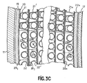
- Each of the combs 29, 29 ' ... 29n is in fact constituted by partial and coextensive combs, welded together by weld lines such as those indicated in fig. 3C par 29 1 , 29 2 ... 29n to extend over an arc whose value depends on the trajectory that one wishes to print on said fluid, and all of these combs constitute deflectors whose arrangement of a level of support systems to another will be explained using fig. 3D.
- combs 29a, 29a ′ , 29a ’ are provided at the various mobile and fixed levels, represented schematically in the form of rings extending at an angle a, each of these rings forming deflectors by means of combs as shown in Fig. 3C
- the angle a is equal to 300 ° and the path impressed on the fluid from one level to another is tilted as much as possible on the axis of the device so as to give a maximum heat transfer coefficient at the level of the tubes not shown in this figure.
- the angle a can also be equal to 240 °, but in all cases, the arrangement of the rings or deflectors is symmetrical between two successive stages, and in the case of this arrangement, the fluid coming from a lower level in direction D is distributed at the next level in directions D and D z .
- the arrangement of the radial arms 14 and 14 ' of FIG. 3, on either side of all of the support systems provided at a given level so that a support system is independent of neighboring support systems, is particularly advantageous for mounting the tubular bundles and the support in the radiator grille placed horizontally, in particular on electric tackers as shown in figs. 4 and 5 in which only two tackers 23 and 24 have been shown tees, the presence of these turners allowing the mounting of the tube bundle in sectors of 60 °, for example delimited by the pairs of radial arms 14-14,14 ' -14' ... 14n-14n.
- the inner ends 15, 15 ′ of the radial arms such as 14, 14 ′ are mounted in openings made in temporary flat irons 25, 26 fixed to the plates 3 and 4 and removed for the placement of the inner cylinder 17 (fig. 3).
- the flat bars 25, 26 are removed and the central tube 27 is put in place as shown in FIG. 6.
- Each deflector 29, 29, ... 29 n can in this case extend over an arc of 306 ° and form a ring whose radial thickness is less than the radial distance between the grille and the central tube, with the particularity that successive rings are arranged alternately on the side of the radiator grille and on the side of the central tube to impart an undulating trajectory to the ascending fluid. It will be noted that the radial thicknesses of the successive rings are different from each other, while the radial thicknesses of the rings which have the same arrangement are equal to each other.
- Fig. 7 shows the sketch used to determine this distribution in the case where we adopt the assembly by secterus of 60 °.
Description
La présente invention concerne un échangeur de chaleur, et elle vise des perfectionnements aux échangeurs de chaleur, notamment applicables à un générateur de vapeur, à tubes droits, de préférence à des tubes ondulés, disposés suivant des nappes verticales, parallèles et maintenus à certains niveaux axiaux, par des systèmes de supportage concentriques dont chacun est constitué par une bande circulaire à alvéoles trapézoïdaux alternés, soudée à une bande de supportage et obturée, après mise en place des tubes, par une bande de fermeture à laquelle est soudée la bande de supportage du système de supportage suivant dans le sens radial de la calandre. Ces systèmes de supportage ont été décrits dans le FR-A-2 420 735.The present invention relates to a heat exchanger, and it relates to improvements in heat exchangers, in particular applicable to a steam generator, with straight tubes, preferably corrugated tubes, arranged in vertical sheets, parallel and maintained at certain levels. axial, by concentric support systems, each of which is constituted by a circular strip with alternating trapezoidal cells, welded to a support strip and closed, after fitting the tubes, by a closure strip to which the support strip is welded of the following support system in the radial direction of the grille. These support systems have been described in FR-A-2 420 735.
Dans le cas préférentiel de la mise en oeuvre de tubes ondulés présentant des ondulations situées d'un même côté de l'axe passant par les extrémités droites des tubes maintenues dans les ouvertures correspondantes prévues dans les plaques d'extrémité de la calandre, à la base des deux dômes généralement utilisés dans ce genre d'appareil, les tubes sont disposés de manière que les plans contenant leurs ondulations soient sensiblement tangents aux cercles des faisceaux tubulaires associés prévus entre la calandre et un tube central de l'échangeur de chaleur.In the preferential case of the use of corrugated tubes having corrugations situated on the same side of the axis passing through the straight ends of the tubes held in the corresponding openings provided in the end plates of the grille, at the base of the two domes generally used in this kind of device, the tubes are arranged so that the planes containing their undulations are substantially tangent to the circles of the associated tubular bundles provided between the shell and a central tube of the heat exchanger.
A cause des différences de température des fluides en présence dans l'appareil, les tubes ondulés se contractent ou se dilatent, plus particulièrement au niveau des ondulations dont les flèches varient, ce qui se traduit par une force tangentielle qui s'exerce sur les divers systèmes de supportage dans les alvéoles desquels sont emprisonnées les parties ondulées des tubes. Et, dans un même secteur des systèmes de supportage concentriques situés à un même niveau, le déplacement périphérique des différentes portions des systèmes de supportage de ce secteur croît du centre vers la calandre.Because of the temperature differences of the fluids present in the device, the corrugated tubes contract or expand, more particularly at the level of the corrugations whose arrows vary, which results in a tangential force which is exerted on the various support systems in the cells of which the corrugated parts of the tubes are trapped. And, in the same sector of concentric support systems located at the same level, the peripheral displacement of the different portions of the support systems of this sector increases from the center towards the grille.
Les systèmes de supportage situés à un même niveau étant soudés les uns aux autres, des tensions préjudiciables peuvent se présenter dans certaines conditions thermiques de fonctionnement et conduire, pour le moins, à une détérioration desdits systèmes de supportage.The support systems located at the same level being welded to each other, harmful voltages can arise under certain thermal operating conditions and lead, at the very least, to a deterioration of said support systems.
Aussi, pour remédier à cet inconvénient, il est prévu, selon l'invention, qu'au moins certains des systèmes de supportage, situés à un même niveau, sont indépendants des systèmes de supportage voisins et forment des groupes de systèmes de supportage,_et ue _bras radiaux sont prévus, pour t'apptn desdits systmes de supportage indépendants, dans l'espace situé entre la calandre et le tube central.Also, to remedy this drawback, it is provided, according to the invention, that at least some of the support systems, located at the same level, are independent of neighboring support systems and form groups of support systems, _and ue _bras radial are provided for the apptn said independent support systems, in the space between the grille and the central tube.
Suivant une forme de réalisation préférée, assurant une souplesse totale de l'ensemble des systèmes de supportage, tous les systèmes de supportage mobiles d'un même niveau sont indépendants l'un de l'autre, et des bras radiaux sont prévus de part et d'autre de l'ensemble des systèmes de supportage d'un même niveau.According to a preferred embodiment, ensuring total flexibility of all the support systems, all the mobile support systems of the same level are independent of each other, and radial arms are provided on both sides. on the other of all support systems of the same level.
Grâce à cette disposition, les systèmes de supportage indépendants l'un de l'autre et appartenant à un même niveau, sont maintenus en place entre la calandre et le tube central de l'échangeur de chaleur qui peut donc également être monté et transporté en position horizontale.Thanks to this arrangement, the support systems independent of one another and belonging to the same level, are held in place between the shell and the central tube of the heat exchanger which can therefore also be mounted and transported in horizontal position.
Avantageusement, chaque bras radial est constitué par deux fers plats soudés sur chant, avec un certain écartement entre eux.Advantageously, each radial arm is constituted by two flat bars welded on edge, with a certain spacing between them.
Suivant une autre forme de réalisation, on prévoit, au moins à certains niveaux, deux anneaux concentriques dont l'un est situé du côté de la face intérieure de la calandre et l'autre du côté de la face extérieure du tube central, le premier pouvant être soudé à la calandre et le second audit tube central, ce qui permet d'améliorer le maintien en place des systèmes de supportage.According to another embodiment, there are provided, at least at certain levels, two concentric rings, one of which is situated on the side of the internal face of the grille and the other on the side of the external face of the central tube, the first can be welded to the grille and the second to said central tube, which improves the retention of support systems.
Dans le cas où l'on souhaite pourvoir l'appareil, au moins à certains niveaux, d'un système de déflecteurs, pour assujettir la circulation du fluide dans la calandre à une certaine trajectoire, en vue d'en discipliner l'écoulement pour obtenir un meilleur coefficient de transmission de la chaleur, il est prévu, selon l'invention, d'associer, à au moins certaines bandes circulaires à alvéoles trapézoïdaux, des bandes circulaires en forme de peignes, s'étendant sur des arcs de longueur appropriée, et dont les dents qui s'étendent radialement vers le centre, passent respectivement entre deux tubes voisins de manière à obturer au maximum les intervalles qui peuvent exister entre ces derniers, lesdits peignes étant posés à plat sur la bande alvéolaire et étant soudés à la bande de supportage voisine.In the case where it is desired to provide the apparatus, at least at certain levels, with a system of deflectors, in order to subject the circulation of the fluid in the grille to a certain trajectory, with a view to disciplining the flow thereof for to obtain a better heat transmission coefficient, it is provided, according to the invention, to combine, with at least certain circular bands with trapezoidal cells, circular bands in the form of combs, extending over arcs of appropriate length , and whose teeth which extend radially towards the center, pass respectively between two neighboring tubes so as to close as much as possible the intervals which may exist between the latter, said combs being laid flat on the alveolar strip and being welded to the neighboring support strip.
Avantageusement, les peignes disposés à un niveau donné sont décalés angulairement par rapport aux peignes disposés au niveau suivant et au niveau précédent, le décalage angulaire étant tel que la projection sur un plan horizontal de deux peignes situés à deux niveaux successifs soit un anneau s'étendant sur 360°. De préférence, le peigne de chaque niveau s'étend suivant un arc de 300°, mais il peut également s'étendre sur 180°, ou moins. Il est bien entendu que des peignes s'étendant sur de tels arcs sont constitués par des morceaux de peignes coextensifs et soudés entre eux.Advantageously, the combs arranged at a given level are angularly offset relative to the combs arranged at the next level and at the previous level, the angular offset being such that the projection on a horizontal plane of two combs located at two successive levels is a ring s' extending over 360 °. Preferably, the comb of each level extends in an arc of 300 °, but it can also extend over 180 °, or less. It is understood that combs extending over such arcs are formed by pieces of coextensive combs and welded together.
En règle générale, un échangeur de chaleur, et plus particulièrement un générateur de vapeur, est un appareil de grandes dimensions, et pour la commodité, la calandre est posée horizontalement sur des vireurs électriques pour permettre 1a mise en place des faisceaux et des systèmes de supportage par secteurs de 60° ou éventuellement de 120°.As a general rule, a heat exchanger, and more particularly a steam generator, is a large device, and for convenience, the radiator grille is placed horizontally on electric turners to allow the placement of the bundles and support by sectors of 60 ° or possibly 120 °.
Afin de permettre cette mise en place dans de bonnes conditions, l'invention propose un procédé qui consiste en ce que les bras radiaux soudés à la face intérieure de la calandre ou à l'anneau qui lui est adjacent, sont supportés à l'aide de fers plats raidisseurs soudés par leurs extrémités aux plaques de fond dans lesquelles sont maintenues les extrémités des tubes et pourvus d'ouvertures pour le passage des extrémités libres des bras radiaux; après mise en place du faisceau tubulaire et des systèmes de supportage, lesdits fers plats raidisseurs sont démontés et le tube central est mis en place et est soudé auxdits bras radiaux par des ouvertures qu'il comporte, ledit tube central pouvant éventuellement être réalisé dans la calandre, par assemblage et soudage d'éléments de parois individuels.In order to allow this to be put in place under good conditions, the invention proposes a method which consists in that the radial arms welded to the inner face of the grille or to the ring which is adjacent to it, are supported using of stiffening flat bars welded at their ends to the bottom plates in which the ends of the tubes are held and provided with openings for the passage of the free ends of the radial arms; after installation of the tube bundle and the support systems, said stiffening flat bars are dismantled and the central tube is put in place and is welded to said radial arms by openings which it comprises, said central tube possibly being able to be produced in the calender, by assembling and welding individual wall elements.
Mais il est également concevable, et généralement plus avantageux, de procéder à la mise en place des faisceaux tubulaires, des systèmes de supportage et des bras radiaux en opérant à partir de la surface extérieure du tube central, des supports appropriés étant prévus, si nécessaire, pour soutenir temporairement les bras radiaux et pour assurer leur position radiale, supports qui sont ensuite supprimés, pour permettre la mise en place de la calandre.But it is also conceivable, and generally more advantageous, to proceed with the installation of the tubular bundles, the support systems and the radial arms by operating from the exterior surface of the central tube, suitable supports being provided, if necessary , to temporarily support the radial arms and to ensure their radial position, supports which are then removed, to allow the establishment of the grille.
Dans le cas particulier de tubes ondulés comportant des portions droites entre les ondulations successives, il a été indiqué qu'en raison des dilatations des tubes au niveau des ondulations, la flèche de chacune de celles-ci peut augmenter dans certaines conditions thermiques et pour tenir compte de ces conditions, il a été proposé que dans ces niveaux, les systèmes de supportage concentriques soient indépendants l'un de l'autre et reposent sur un bras radial ou soient situés entre des paires de couples de bras radiaux situés entre la calandre et le tube central. Dans ce qui suit, ces niveaux seront désignés par «niveaux à mobilité» ou plus brièvement par «niveau mobile».In the particular case of corrugated tubes having straight portions between the successive corrugations, it has been indicated that due to the dilations of the tubes at the level of the corrugations, the deflection of each of these can increase under certain thermal conditions and to hold In view of these conditions, it has been proposed that in these levels, the concentric support systems are independent of each other and rest on a radial arm or are located between pairs of pairs of radial arms located between the grille and the central tube. In what follows, these levels will be designated by “mobility levels” or more briefly by “mobile level”.
Par contre, au niveau des portions droites des tubes, situées entre deux ondulations, il n'y a aucune dilatation pouvant conduire à une mobilité dans le sens périphérique des systèmes de supportage concentriques prévus à ce niveau, qui sera désigné par «niveaux fixes». Aussi, on pourra à ces niveaux fixes prévoir des soudures entre les bras radiaux et au moins certains des systèmes de supportage; ces soudures pourront être réalisées entre le ou les bras radiaux d'une part, et l'une ou l'autre des bandes constitutives des systèmes de supportage d'autre part.On the other hand, at the level of the straight portions of the tubes, situated between two corrugations, there is no expansion which can lead to mobility in the peripheral direction of the concentric support systems provided at this level, which will be designated by "fixed levels" . Also, it will be possible at these fixed levels to provide welds between the radial arms and at least some of the support systems; these welds can be made between the radial arm (s) on the one hand, and one or other of the constituent bands of the support systems on the other hand.
A titre d'exemple, on a décrit ci-dessous, et représenté au dessin annexé, différentes formes de réalisation de l'objet de l'invention.
- La fig. 1 est une vue schématique d'un tube ondulé du type destiné à être mis en oeuvre dans le cadre de l'invention.
- La fig. 2 est une vue schématique et partielle d'un faisceau de tubes selon la fig. 1, montrant la déformation que peut subir un tube au niveau mobile.
- La fig. 3 représente schématiquement une coupe radiale au niveau d'un système de supportage de tubes.
- Les fig. 3A et 3B montrent respectivement en perspective l'agencement de deux portions de systèmes de supportage à un niveau mobile et à niveau fixe.
- La fig. 3C est une coupe de la fig. 3 selon la ligne III C-III C.
- La fig. 3D est une vue schématique partielle avec arrangement des déflecteurs constitués par des peignes.
- La fig. 4 est une vue axiale schématique d'un appareil selon l'invention, en position horizontale.
- La fig. 5 est une coupe axiale de la fig. 4 selon la ligne V-V montrant deux des vireurs électriques sur lesquels repose l'appareil de la fig. 4.
- La fig. 6 montre schématiquement la disposition des déflecteurs réalisés à l'aide de peignes.
- La fig. 7 montre une épure permettant de déterminer la répartition des tubes dans des secteurs de 60°.
- La fig. 8 est une coupe schématique et partielle montrant la disposition d'un faisceau tubulaire réparti par secteurs de 120° entre la calandre et le tube central.
- Fig. 1 is a schematic view of a corrugated tube of the type intended to be used in the context of the invention.
- Fig. 2 is a schematic and partial view of a bundle of tubes according to FIG. 1, showing the deformation that a tube can undergo at the mobile level.
- Fig. 3 schematically represents a radial section at the level of a tube support system.
- Figs. 3A and 3B respectively show in perspective the arrangement of two portions of support systems at a mobile level and at a fixed level.
- Fig. 3C is a section of FIG. 3 along line III C-III C.
- Fig. 3D is a partial schematic view with arrangement of the deflectors constituted by combs.
- Fig. 4 is a schematic axial view of an apparatus according to the invention, in a horizontal position.
- Fig. 5 is an axial section of FIG. 4 along the line VV showing two of the electric turners on which the apparatus of FIG. 4.
- Fig. 6 schematically shows the arrangement of the deflectors produced using combs.
- Fig. 7 shows a diagram for determining the distribution of the tubes in sectors of 60 °.
- Fig. 8 is a schematic and partial section showing the arrangement of a tubular bundle distributed by sectors of 120 ° between the grille and the central tube.
Dans la fig. 1, on a représenté schématiquement l'allure générale d'un tube à ondulations, approprié à la mise en oeuvre de l'invention. Ce tube est monté par ses deux extrémités droites 1 et 2 dans les plaques 3 et 4 prévues habituellement à la base des dômes supérieur et inférieur que comporte un générateur de vapeur ou plus généralement un échangeur de chaleur. Entre ces extrémités droites 1 et 2, le tube comporte des ondulations dont deux seulement ont été représentées en 5 et 6. Ces ondulations 5 et 6 sont situées d'un même côté d'une portion droite 7 qui relie deux ondulations successives et qui est alignée avec les extrémités 1 et 2, et elles y sont raccordées par des portions courbes 8 et 9, alors qu'elles sont raccordées respectivement aux extrémités droites 1 et 2 par les portions courbes 9 et 10.In fig. 1, there is shown schematically the general appearance of a corrugated tube, suitable for implementing the invention. This tube is mounted by its two
Ainsi que cela ressort de la fig. 2, les tubes ondulés sont disposés de manière que le plan contenant l'axe des ondulations et celui des portions droites se situe sensiblement dans le plan tangentiel au cercle de l'alignement circonférentiel des tubes de la rangée circulaire concernée du faisceau. Dans cette figure, la référence 5 désigne l'ondulation correspondante de la fig. 1, et on y a indiqué la flèche f de l'ondulation au repos. Lors d'une déformation, sous l'effet de la température, la flèche f augmente et prend la valeur f', et elle passe de 10 à 10' .As is apparent from FIG. 2, the corrugated tubes are arranged so that the plane containing the axis of the corrugations and that of the straight portions lies substantially in the plane tangential to the circle of the circumferential alignment of the tubes of the relevant circular row of the bundle. In this figure, the
Or, entre les plaques 3 et 4, il a été proposé de prévoir, en particulier au niveau (niveau mobile) des sommets des ondulations telles que celles désignées par 5, des systèmes concentriques de supportage dont chacun est constitué par une bande de supportage à laquelle est soudée une bande alvéolaire à alvéoles successifs alternés dans lesquels sont logées lesdites ondulations et de fermer les alvéoles par une bande de fermeture à laquelle est soudée la bande de supportage suivante et ainsi de proche en proche entre la calandre et un tube central disposé dans ce dernier.However, between the
De ce fait, dans un seul et même niveau mobile, les systèmes de supportage concentriques forment entre la calandre et le tube central un ensemble d'un seul tenant et les portions des systèmes de supportage concentriques et sous-tendant un même angle au centre, subissent, pour une même température, des dilatations périphériques qui croissent du centre vers la calandre.Therefore, in one and the same mobi level the, the concentric support systems form between the calender and the central tube a whole in one piece and the portions of the concentric support systems and subtending a same angle in the center, undergo, for the same temperature, peripheral dilations which grow from the center to the grille.
Pour remédier à cet inconvénient, l'invention propose la disposition de la fig. 3.To remedy this drawback, the invention proposes the arrangement of FIG. 3.
En dessous du niveau du sommet d'une ondulation telle que 5 de la fig. 1, on soude en 12 et 13, un fer plat 14 monté sur chant dont l'autre extrémité 15 sera supportée provisoirement comme il sera expliqué plus loin à propos de la fig. 4, pour finalement être soudée en 16 au tube central 17.Below the level of the top of a corrugation such as 5 of FIG. 1, we weld in 12 and 13, a
Sur ce bras radial, on place près de la face intérieure 18 de la calandre 11 un anneau 19 en position verticale. Contre la face intérieure de l'anneau est placée une bande annulaire de supportage 20 et à celle-ci est soudée une bande alvéolaire 21 telle que décrite dans le FR-A-2 420 735, et dans les alvéoles de laquelle sont placés les tubes tels que celui désigné par 5, et maintenus en place par une bande de fermeture 22 soudée à la bande alvéolaire 21.On this radial arm, a
A l'intérieur de ce système de supportage 20, 21, 22 pour les tubes tels que 5, on dispose les systèmes de supportage 20', 21', 22' pour les tubes 5', et de proche en proche le système de supportage 20n, 21n, pour les tubes 5n dont les alvéoles sont fermés par l'anneau 22n qui est l'équivalent des bandes de fermeture 22, 22', l'anneau 22n étant soudé à la paroi du tube central 17.Inside this
On a ainsi réalisé des systèmes concentriques de supportage, indépendants les uns des autres, en sorte que la dilatation circonférentielle de l'un des systèmes est indépendante du ou des systèmes voisins.Concentric support systems have thus been produced, independent of each other, so that the circumferential expansion of one of the systems is independent of the neighboring system or systems.
De préférence, on place sur la nappe des systèmes de supportage ainsi réalisée un bras radial 14' analogue au bras radial 14, et avantageusement chaque bras radial 14 et 14' sera constitué par deux fers plats tels que ceux désignés par 14 et 14' et qui seront disposés de part et d'autre de la rangée radiale des tubes 5,, 5' ... 5n.Preferably, a
La fig. 3A montre en perspective deux morceaux de deux systèmes de supportage successifs entre les bras radiaux et disposés à un niveau mobile. Le système de supportage extérieur est constitué par la bande de supportage 20 à laquelle est soudée, par des points de soudure tels que celui indiqué par S, la bande alvéolaire 21 contre laquelle est appliquée librement la bande de fermeture 22. Le système de supportage intérieur est constitué de la même manière par la bande de supportage 20', par la bande alvéolaire 21' et par la bande de fermeture 22', avec le même point de soudure S, l'ensemble des deux systèmes de supportage étant disposé librement entre les bras radiaux 14 et 14'. Et, selon l'invention, il n'est prévu aucune soudure entre les deux systèmes de supportage. Si on le désire, un point de soudure peut être prévu entre 21 et 22 et entre 21' et 22'.Fig. 3A shows in perspective two pieces of two successive support systems between the radial arms and arranged at a movable level. The external support system consists of the
La fig. 3B montre une disposition identique à celle de la fig. 3A, mais pour un «niveau fixe», avec cette double différence que l'on n'y prévoit que le seul bras radial 14 et une soudure S" entre le bras 14 et la bande de fermeture 22', étant entendu qu'une telle soudure S" peut être prévue entre le bras 14 et la bande de fermeture de chaque système de supportage tel que celui désigné par 22,22'.Fig. 3B shows an arrangement identical to that of FIG. 3A, but for a "fixed level", with this double difference that only the
Pour discipliner l'écoulement du fluide dans l'échangeur de chaleur, en vue d'obtenir un meilleur coefficient de transmission superficielle de chaleur, il est prévu de disposer sur au moins certains des systèmes de supportage des bandes 29 en forme de peignes qui sont visibles en fig. 3C, qui est une coupe de la fig. 3 le long de la ligne III C-III C.To discipline the flow of the fluid in the heat exchanger, with a view to obtaining a better coefficient of surface heat transmission, provision is made to have at least some of the support systems for
Ainsi que cela ressort des fig. 3 et 3C, les peignes 29, 29' ... 29n sont associés respectivement aux rangées des tubes 5, 5' ... 5n et sont posés à plat sur les bandes alvéolaires 21, 21' ... 21 n et maintenus en place par soudure aux bandes de supportage 20, 20' ... 20n dans une position telle que les dents de chaque peigne 29, 29' ... 29n passent entre les tubes maintenus par les bandes alvéolaires respectives 21, 2T ... 21 n.As is apparent from FIGS. 3 and 3C, the
Chacun des peignes 29, 29' ... 29n est en fait constitué par des peignes partiels et coextensifs, soudés entre eux par des lignes de soudure telles que celles indiquées en fig. 3C par 291, 292 ... 29n pour s'étendre sur un arc dont la valeur dépend de la trajectoire que l'on souhaite imprimer audit fluide, et l'ensemble de ces peignes constitue des déflecteurs dont la disposition d'un niveau de systèmes de supportage à un autre sera explicité à l'aide de la fig. 3D.Each of the
Entre la calandre 11 et le tube central, on dispose aux différents niveaux mobiles et fixes, respectivement des peignes 29a, 29a', 29a" représentés schématiquement sous la forme d'anneaux s'étendant sur un angle a, chacun de ces anneaux formant des déflecteurs au moyen de peignes tels que représentés à la fig. 3C. Dans la fig. 3D, l'angle a est égal à 300° et la trajectoire imprimée au fluide d'un niveau à un autre est inclinée au maximum sur l'axe de l'appareil de manière à donner un coefficient de transfert de chaleur maximum au niveau des tubes non représentés dans cette figure. Mais l'angle a peut aussi être égal à 240°, mais dans tous les cas, la disposition des anneaux ou déflecteurs est symétrique entre deux étages successfis. Et dans le cas de cette disposition, le fluide venant d'un niveau inférieur selon la direction D se répartit au niveau suivant selon les directions D, et Dz.Between the
La disposition des bras radiaux 14 et 14' de la fig. 3, de part et d'autre de l'ensemble des systèmes de supportage prévus à un niveau donné de façon qu'un système de supportage soit indépendant des systèmes de supportage voisins, est particulièrement avantageuse pour le montage des faisceaux tubulaires et des systèmes de supportage dans la calandre placée horizontalement, notamment sur des vireurs électriques comme représenté dans les fig. 4 et 5 dans lesquelles deux vireurs 23 et 24 seulement ont été représentés, la présence de ces vireurs permettant le montage du faisceau tubulaire par secteurs de 60°, par exemple délimités par les paires de bras radiaux 14-14,14'-14' ... 14n-14n.The arrangement of the
Dans ce genre de montage, les extrémités intérieures 15, 15' des bras radiaux tels que 14, 14' sont montées dans des ouvertures ménagées dans des fers plats provisoires 25, 26 fixés aux plateaux 3 et 4 et enlevés pour la mise en place du cylindre intérieur 17 (fig. 3). Après mise en place du faisceau de tubes et des systèmes de supportage, on supprime les fers plats 25, 26 et l'on-met en place le tube central 27 tel que représenté en fig. 6.In this type of mounting, the inner ends 15, 15 ′ of the radial arms such as 14, 14 ′ are mounted in openings made in temporary
Celle-ci est une coupe axiale et schématique de l'appareil selon l'invention et montre la présence de déflecteurs 29, 291 ... 29n réalisés au moyen de peignes 29 à 29m placés à plat que les bandes alvéolaires 21 à 21 n de manière que les dents passent entre les tubes d'une rangée circulaire, comme décrit à propos des fig. 3 et 3A.This is an axial and schematic section of the device according to the invention and shows the presence of
Chaque déflecteur 29, 29, ... 29n peut s'étendre dans ce cas sur un arc de 306° etforme un anneau dont l'épaisseur radiale est inférieure à la distance radiale entre la calandre et le tube central, avec cette particularité que les anneaux successifs sont disposés alternativement du côté de la calandre et du côté du tube central pour imprimer au fluide ascendant une trajectoire ondulée. On notera que les épaisseurs radiales des anneaux successifs sont différentes entre elles, alors que les épaisseurs radiales des anneaux qui ont la même disposition sont égales entre elles.Each
Il ressort de ce qui précède que le montage des systèmes circulaires de supportage et leur garnissage par secteurs de 60°, de 120° ou de 180°, et celui des sections correspondantes de la bande de supportage à laquelle est soudée la bande alvéolaire, peuvent être préparés à l'avance, en dehors de la calandre, en fonction de la disposition à adopter pour la répartition du tube, ce qui conduit à une réalisation en grande série du système de supportage.It emerges from the above that the mounting of the circular support systems and their lining in sectors of 60 °, 120 ° or 180 °, and that of the corresponding sections of the support strip to which the cellular strip is welded, can be prepared in advance, outside the grille, depending on the arrangement to be adopted for the distribution of the tube, which leads to a mass production of the support system.
La fig. 7 montre l'épure servant à déterminer cette répartition dans le cas où l'on adopte le montage par secterus de 60°.Fig. 7 shows the sketch used to determine this distribution in the case where we adopt the assembly by secterus of 60 °.
On commence par tracer un hexagone régulier 29 avec pour centre l'origine O de deux axes de coordonnées X, Y. Sur les côtés 30, 31 on trace les médiatrices 30, 31. Dans le secteur 30-O-31, on marque l'emplacement d'un premier tube 32 au sommet de l'hexagone, après tracé des cercles concentriques au pas radial p, on marque les emplacements des autres tubes dont le nombre augmente d'une unité par pas radial, entre les médiatrices 30, 31, avec une symétrie par rapport à l'axe OY qui est la bissectrice de l'angle 30, 0, 31. On procède de manière identique à l'établissement de l'épure pour les autres secteurs de 60°, en notant que les bras radiaux seront disposés parallèlement aux médiatrices 30, 31.We start by drawing a
Une fois le tracé effectué, on détermine le diamètre du tube inférieur 37, tracé dans la fig. 8, dans lequel il n'y a pas lieu de disposer de tubes ondulés.Once the tracing has been made, the diameter of the
Claims (10)
Priority Applications (1)
| Application Number | Priority Date | Filing Date | Title |
|---|---|---|---|
| AT82400008T ATE5614T1 (en) | 1981-01-08 | 1982-01-05 | HEAT EXCHANGER WITH BUNDLES OF STRAIGHT OR CORRUGATED TUBES, ESPECIALLY ON PIPE SUPPORT SYSTEMS, AND METHOD OF IMPLEMENTING SUCH SYSTEMS. |
Applications Claiming Priority (4)
| Application Number | Priority Date | Filing Date | Title |
|---|---|---|---|
| FR8100212 | 1981-01-08 | ||
| FR8100212A FR2497566B1 (en) | 1981-01-08 | 1981-01-08 | IMPROVEMENT IN HEAT EXCHANGERS |
| FR8102993 | 1981-02-16 | ||
| FR8102993A FR2500144B1 (en) | 1981-02-16 | 1981-02-16 | IMPROVEMENT IN HEAT EXCHANGERS HAVING STRAIGHT OR CORRUGATED TUBE BEAMS, IN PARTICULAR TO TUBE SUPPORT SYSTEMS AND METHOD FOR THE PRODUCTION OF SUCH SUPPORT SYSTEMS |
Publications (3)
| Publication Number | Publication Date |
|---|---|
| EP0056744A2 EP0056744A2 (en) | 1982-07-28 |
| EP0056744A3 EP0056744A3 (en) | 1982-08-04 |
| EP0056744B1 true EP0056744B1 (en) | 1983-12-14 |
Family
ID=26222174
Family Applications (1)
| Application Number | Title | Priority Date | Filing Date |
|---|---|---|---|
| EP82400008A Expired EP0056744B1 (en) | 1981-01-08 | 1982-01-05 | Heat exchangers with bundles of straight or undulating tubes, especially on systems of supporting tubes, and method of realising such systems |
Country Status (5)
| Country | Link |
|---|---|
| US (1) | US4573528A (en) |
| EP (1) | EP0056744B1 (en) |
| BR (1) | BR8200057A (en) |
| CA (1) | CA1208995A (en) |
| DE (1) | DE3260017D1 (en) |
Families Citing this family (5)
| Publication number | Priority date | Publication date | Assignee | Title |
|---|---|---|---|---|
| DE3904140C1 (en) * | 1989-02-11 | 1990-04-05 | Mtu Muenchen Gmbh | |
| US5311271A (en) * | 1992-01-21 | 1994-05-10 | Dme/Golf, Inc. | Golf course range finder |
| US6702190B1 (en) | 2001-07-02 | 2004-03-09 | Arvin Technologies, Inc. | Heat transfer system for a vehicle |
| US7152665B2 (en) * | 2003-05-08 | 2006-12-26 | Kabushiki Kaisha Toyota Jidoshokki | Pressure tank |
| JPWO2014174692A1 (en) * | 2013-04-25 | 2017-02-23 | 三菱重工業株式会社 | Heat transfer tube vibration suppressing member and manufacturing method thereof, heat transfer tube vibration suppressing device and method, steam generator |
Family Cites Families (29)
| Publication number | Priority date | Publication date | Assignee | Title |
|---|---|---|---|---|
| FR65106E (en) * | 1953-12-31 | 1956-01-26 | Chausson Usines Sa | heat exchanger in particular for aircraft and similar applications |
| US2942855A (en) * | 1955-08-17 | 1960-06-28 | Rekuperator K G Dr Ing Schack | Recuperator |
| US2980404A (en) * | 1957-11-07 | 1961-04-18 | Union Carbide Corp | Heat exchange device |
| US2978226A (en) * | 1958-12-18 | 1961-04-04 | Gen Electric | Tube type heat exchanger |
| US3134432A (en) * | 1962-06-20 | 1964-05-26 | United Aircraft Corp | Heat exchanger |
| DE1303351B (en) * | 1963-04-01 | Hitachi Ltd | ||
| FR1364849A (en) * | 1963-06-07 | 1964-06-26 | Motala Verkstad Ab | Shoring device for tubes, rods or the like in steam generators, tubular heat exchangers or others |
| US3336974A (en) * | 1965-05-05 | 1967-08-22 | United Aircraft Corp | Serpentine tube boiler |
| FR1491534A (en) * | 1966-07-01 | 1967-08-11 | Ct D Etudes Pour L Ind Pharma | Advanced refrigerant |
| US3420297A (en) * | 1967-04-25 | 1969-01-07 | Combustion Eng | Heat exchanger tube support and spacing structure |
| GB1280662A (en) * | 1969-01-28 | 1972-07-05 | Atomic Energy Authority Uk | Improvements in or relating to tubular heat exchangers |
| FR2077865A1 (en) * | 1970-02-19 | 1971-11-05 | Trepaud Georges | Cylindrical heat exchanger - with twin helical passages surrounding central tube bundle |
| GB1306864A (en) * | 1970-08-25 | 1973-02-14 | Head Wrightson & Co Ltd | Tubular heat exchangers |
| US3683866A (en) * | 1970-11-20 | 1972-08-15 | Combustion Eng | Superheating steam generator |
| DE2100664A1 (en) * | 1971-01-08 | 1972-07-20 | The Batteile Development Corp., Columbus, Ohio (V.StA.) | Evaporator for refrigeration systems |
| FR2172799A1 (en) * | 1972-02-22 | 1973-10-05 | Trepaud Georges | Nuclear reactor heat exchanger - with central shaft giving access for tube installation and repair |
| US3989105A (en) * | 1972-02-22 | 1976-11-02 | Georges Trepaud | Heat exchanger |
| US3782455A (en) * | 1972-05-01 | 1974-01-01 | Atomic Energy Commission | Heat exchanger tube mounts |
| FR2266866A2 (en) * | 1974-04-03 | 1975-10-31 | Trepaud Georges | Heat exchanger with tube bundle - having tubes each shaped in wave-form and having supports preventing axial rotation |
| FR2293684A2 (en) * | 1974-12-05 | 1976-07-02 | Trepaud Georges | TUBULAR BEAM HEAT EXCHANGER |
| DE2613745A1 (en) * | 1976-03-31 | 1977-10-06 | Linde Ag | HEAT EXCHANGER |
| FR2355191A1 (en) * | 1976-06-16 | 1978-01-13 | Creusot Loire | DEVICE FOR HOLDING A TAPE OF TUBES WITHIN A SPEAKER |
| US4154295A (en) * | 1977-02-02 | 1979-05-15 | General Atomic Company | Heat exchanger tube support assembly |
| FR2420735A2 (en) * | 1978-03-24 | 1979-10-19 | Trepaud Georges | TUBULAR BEAM HEAT EXCHANGER |
| US4210202A (en) * | 1978-03-30 | 1980-07-01 | Ecolaire Incorporated | Support for heat exchange tubes |
| US4253516A (en) * | 1978-06-22 | 1981-03-03 | Westinghouse Electric Corp. | Modular heat exchanger |
| FR2459441A1 (en) * | 1979-06-19 | 1981-01-09 | Stein Industrie | Grid for supporting rows of tubes in heat exchanger - where grid is formed by plates provided with bosses clamping the tubes |
| FR2461221A1 (en) * | 1979-07-11 | 1981-01-30 | Stein Industrie | Heat exchanger tube support plate - fits in grooves in ends of fixed ring inside exchanger |
| US4325171A (en) * | 1979-10-15 | 1982-04-20 | Econo-Therm Energy Systems Corporation | Means and method for sealing heat exchanger walls |
-
1981
- 1981-12-29 US US06/335,537 patent/US4573528A/en not_active Expired - Fee Related
-
1982
- 1982-01-05 EP EP82400008A patent/EP0056744B1/en not_active Expired
- 1982-01-05 CA CA000393584A patent/CA1208995A/en not_active Expired
- 1982-01-05 DE DE8282400008T patent/DE3260017D1/en not_active Expired
- 1982-01-07 BR BR8200057A patent/BR8200057A/en unknown
Also Published As
| Publication number | Publication date |
|---|---|
| CA1208995A (en) | 1986-08-05 |
| EP0056744A2 (en) | 1982-07-28 |
| US4573528A (en) | 1986-03-04 |
| EP0056744A3 (en) | 1982-08-04 |
| BR8200057A (en) | 1982-10-26 |
| DE3260017D1 (en) | 1984-01-19 |
Similar Documents
| Publication | Publication Date | Title |
|---|---|---|
| EP0596786B1 (en) | Spacer grid provided with vanes for nuclear fuel assembly | |
| FR2465297A1 (en) | SPACING GRID FOR COMBUSTIBLE ELEMENTS OF NUCLEAR REACTORS | |
| FR2707382A1 (en) | Heat exchanger comprising a bundle of U-bent tubes and anti-vibration bars between the bent parts of the tubes. | |
| EP0056744B1 (en) | Heat exchangers with bundles of straight or undulating tubes, especially on systems of supporting tubes, and method of realising such systems | |
| FR2618198A1 (en) | DEVICE FOR ANTIVIBRATORY SETTING OF COMPONENTS OF A SYSTEM AND IN PARTICULAR ANTIVIBRATORY SETTING BARS FOR TUBES OF A STEAM GENERATOR. | |
| FR2488383A1 (en) | SHIFTING NETWORK SUPPORTING A BEAM OF PARALLEL CYLINDRICAL BODIES SCANNED LONGITUDINALLY BY A HEAT TRANSFER FLUID | |
| FR2848292A1 (en) | PLATE OF A HEAT EXCHANGER AND PLATE HEAT EXCHANGER | |
| CH622091A5 (en) | ||
| EP0166989A1 (en) | Vertical tube heat exchange panel for recovery boilers, such as black liquor boilers or town refuse incinerators, and manufacturing processes | |
| FR2504666A1 (en) | COOLING TOWER, IN PARTICULAR FOR AN ELECTRIC POWER PLANT | |
| FR2515330A1 (en) | DEVICE FOR THE ANTI-VIBRATION HOLDING OF A BEAM OF TUBES, IN PARTICULAR FOR A STEAM GENERATOR, AND METHOD FOR MOUNTING SUCH A DEVICE | |
| WO2018002544A2 (en) | Mechanical heat exchanger and associated production method | |
| FR2500144A1 (en) | Heat exchanger for stream generator etc. - has corrugated tubes and fixed and free radial supports at crests, with honeycomb structures and baffle rings between | |
| EP1295077A1 (en) | Exchanger with multiple spacing | |
| FR2684172A1 (en) | HEAT EXCHANGER, WITH U-TUBES EQUIPPED WITH AN ANTI-THEFT SUPPORT DEVICE. | |
| FR2609832A1 (en) | LIGHT WATER REACTOR COMBUSTIBLE FUEL ASSEMBLY ASSEMBLY | |
| CH615525A5 (en) | ||
| FR2538889A1 (en) | Flat plate heat exchanger | |
| EP0099835A2 (en) | Heat exchanger with a modular structure | |
| FR2462767A2 (en) | Nuclear fuel element storage frame - with freedom of motion for grid sheets relative to structure | |
| EP0409739B1 (en) | Radiator for central heating | |
| EP0553340B1 (en) | Plate-type heat exchanger | |
| FR3086742A1 (en) | PLATE FOR A PLATE HEAT EXCHANGER | |
| FR2497566A1 (en) | Heat exchanger for stream generator etc. - has corrugated tubes and fixed and free radial supports at crests, with honeycomb structures and baffle rings between | |
| EP2635867B1 (en) | Heat exchanger having welded plates, and plate forming a component of such a heat exchanger |
Legal Events
| Date | Code | Title | Description |
|---|---|---|---|
| PUAI | Public reference made under article 153(3) epc to a published international application that has entered the european phase |
Free format text: ORIGINAL CODE: 0009012 |
|
| PUAL | Search report despatched |
Free format text: ORIGINAL CODE: 0009013 |
|
| AK | Designated contracting states |
Designated state(s): AT BE CH DE GB IT LU NL SE |
|
| AK | Designated contracting states |
Designated state(s): AT BE CH DE GB IT LU NL SE |
|
| 17P | Request for examination filed |
Effective date: 19820805 |
|
| ITF | It: translation for a ep patent filed |
Owner name: STUDIO INGG. FISCHETTI & WEBER |
|
| GRAA | (expected) grant |
Free format text: ORIGINAL CODE: 0009210 |
|
| AK | Designated contracting states |
Designated state(s): AT BE CH DE GB IT LI LU NL SE |
|
| PGFP | Annual fee paid to national office [announced via postgrant information from national office to epo] |
Ref country code: LU Payment date: 19831214 Year of fee payment: 3 |
|
| REF | Corresponds to: |
Ref document number: 5614 Country of ref document: AT Date of ref document: 19831215 Kind code of ref document: T |
|
| PGFP | Annual fee paid to national office [announced via postgrant information from national office to epo] |
Ref country code: CH Payment date: 19840106 Year of fee payment: 3 |
|
| REF | Corresponds to: |
Ref document number: 3260017 Country of ref document: DE Date of ref document: 19840119 |
|
| PG25 | Lapsed in a contracting state [announced via postgrant information from national office to epo] |
Ref country code: LU Free format text: LAPSE BECAUSE OF NON-PAYMENT OF DUE FEES Effective date: 19840131 |
|
| PLBE | No opposition filed within time limit |
Free format text: ORIGINAL CODE: 0009261 |
|
| STAA | Information on the status of an ep patent application or granted ep patent |
Free format text: STATUS: NO OPPOSITION FILED WITHIN TIME LIMIT |
|
| PGFP | Annual fee paid to national office [announced via postgrant information from national office to epo] |
Ref country code: DE Payment date: 19841029 Year of fee payment: 4 |
|
| 26N | No opposition filed | ||
| PGFP | Annual fee paid to national office [announced via postgrant information from national office to epo] |
Ref country code: SE Payment date: 19841231 Year of fee payment: 4 Ref country code: BE Payment date: 19841231 Year of fee payment: 4 |
|
| PGFP | Annual fee paid to national office [announced via postgrant information from national office to epo] |
Ref country code: AT Payment date: 19851126 Year of fee payment: 5 |
|
| PGFP | Annual fee paid to national office [announced via postgrant information from national office to epo] |
Ref country code: NL Payment date: 19860131 Year of fee payment: 5 |
|
| PG25 | Lapsed in a contracting state [announced via postgrant information from national office to epo] |
Ref country code: AT Effective date: 19870105 |
|
| PG25 | Lapsed in a contracting state [announced via postgrant information from national office to epo] |
Ref country code: LI Effective date: 19870131 Ref country code: CH Effective date: 19870131 |
|
| BERE | Be: lapsed |
Owner name: TREPAUD GEORGES Effective date: 19870131 |
|
| PG25 | Lapsed in a contracting state [announced via postgrant information from national office to epo] |
Ref country code: NL Effective date: 19870801 |
|
| GBPC | Gb: european patent ceased through non-payment of renewal fee | ||
| NLV4 | Nl: lapsed or anulled due to non-payment of the annual fee | ||
| REG | Reference to a national code |
Ref country code: CH Ref legal event code: PL |
|
| PG25 | Lapsed in a contracting state [announced via postgrant information from national office to epo] |
Ref country code: DE Effective date: 19871001 |
|
| PG25 | Lapsed in a contracting state [announced via postgrant information from national office to epo] |
Ref country code: SE Effective date: 19880106 |
|
| PG25 | Lapsed in a contracting state [announced via postgrant information from national office to epo] |
Ref country code: GB Effective date: 19881121 |
|
| PG25 | Lapsed in a contracting state [announced via postgrant information from national office to epo] |
Ref country code: BE Effective date: 19890131 |
|
| EUG | Se: european patent has lapsed |
Ref document number: 82400008.7 Effective date: 19880913 |