EP0056435B1 - Katalysatorkörper - Google Patents
Katalysatorkörper Download PDFInfo
- Publication number
- EP0056435B1 EP0056435B1 EP81108655A EP81108655A EP0056435B1 EP 0056435 B1 EP0056435 B1 EP 0056435B1 EP 81108655 A EP81108655 A EP 81108655A EP 81108655 A EP81108655 A EP 81108655A EP 0056435 B1 EP0056435 B1 EP 0056435B1
- Authority
- EP
- European Patent Office
- Prior art keywords
- sheet metal
- metal strips
- adhesive
- following features
- wound
- Prior art date
- Legal status (The legal status is an assumption and is not a legal conclusion. Google has not performed a legal analysis and makes no representation as to the accuracy of the status listed.)
- Expired
Links
Images


Classifications
-
- F—MECHANICAL ENGINEERING; LIGHTING; HEATING; WEAPONS; BLASTING
- F01—MACHINES OR ENGINES IN GENERAL; ENGINE PLANTS IN GENERAL; STEAM ENGINES
- F01N—GAS-FLOW SILENCERS OR EXHAUST APPARATUS FOR MACHINES OR ENGINES IN GENERAL; GAS-FLOW SILENCERS OR EXHAUST APPARATUS FOR INTERNAL-COMBUSTION ENGINES
- F01N3/00—Exhaust or silencing apparatus having means for purifying, rendering innocuous, or otherwise treating exhaust
- F01N3/08—Exhaust or silencing apparatus having means for purifying, rendering innocuous, or otherwise treating exhaust for rendering innocuous
- F01N3/10—Exhaust or silencing apparatus having means for purifying, rendering innocuous, or otherwise treating exhaust for rendering innocuous by thermal or catalytic conversion of noxious components of exhaust
- F01N3/24—Exhaust or silencing apparatus having means for purifying, rendering innocuous, or otherwise treating exhaust for rendering innocuous by thermal or catalytic conversion of noxious components of exhaust characterised by constructional aspects of converting apparatus
- F01N3/28—Construction of catalytic reactors
- F01N3/2803—Construction of catalytic reactors characterised by structure, by material or by manufacturing of catalyst support
- F01N3/2807—Metal other than sintered metal
- F01N3/281—Metallic honeycomb monoliths made of stacked or rolled sheets, foils or plates
-
- B—PERFORMING OPERATIONS; TRANSPORTING
- B01—PHYSICAL OR CHEMICAL PROCESSES OR APPARATUS IN GENERAL
- B01J—CHEMICAL OR PHYSICAL PROCESSES, e.g. CATALYSIS OR COLLOID CHEMISTRY; THEIR RELEVANT APPARATUS
- B01J37/00—Processes, in general, for preparing catalysts; Processes, in general, for activation of catalysts
- B01J37/02—Impregnation, coating or precipitation
- B01J37/0215—Coating
- B01J37/0225—Coating of metal substrates
-
- B—PERFORMING OPERATIONS; TRANSPORTING
- B01—PHYSICAL OR CHEMICAL PROCESSES OR APPARATUS IN GENERAL
- B01J—CHEMICAL OR PHYSICAL PROCESSES, e.g. CATALYSIS OR COLLOID CHEMISTRY; THEIR RELEVANT APPARATUS
- B01J37/00—Processes, in general, for preparing catalysts; Processes, in general, for activation of catalysts
- B01J37/02—Impregnation, coating or precipitation
- B01J37/024—Multiple impregnation or coating
-
- F—MECHANICAL ENGINEERING; LIGHTING; HEATING; WEAPONS; BLASTING
- F01—MACHINES OR ENGINES IN GENERAL; ENGINE PLANTS IN GENERAL; STEAM ENGINES
- F01N—GAS-FLOW SILENCERS OR EXHAUST APPARATUS FOR MACHINES OR ENGINES IN GENERAL; GAS-FLOW SILENCERS OR EXHAUST APPARATUS FOR INTERNAL-COMBUSTION ENGINES
- F01N2330/00—Structure of catalyst support or particle filter
- F01N2330/02—Metallic plates or honeycombs, e.g. superposed or rolled-up corrugated or otherwise deformed sheet metal
- F01N2330/04—Methods of manufacturing
-
- F—MECHANICAL ENGINEERING; LIGHTING; HEATING; WEAPONS; BLASTING
- F01—MACHINES OR ENGINES IN GENERAL; ENGINE PLANTS IN GENERAL; STEAM ENGINES
- F01N—GAS-FLOW SILENCERS OR EXHAUST APPARATUS FOR MACHINES OR ENGINES IN GENERAL; GAS-FLOW SILENCERS OR EXHAUST APPARATUS FOR INTERNAL-COMBUSTION ENGINES
- F01N2330/00—Structure of catalyst support or particle filter
- F01N2330/30—Honeycomb supports characterised by their structural details
- F01N2330/32—Honeycomb supports characterised by their structural details characterised by the shape, form or number of corrugations of plates, sheets or foils
- F01N2330/322—Corrugations of trapezoidal form
-
- F—MECHANICAL ENGINEERING; LIGHTING; HEATING; WEAPONS; BLASTING
- F01—MACHINES OR ENGINES IN GENERAL; ENGINE PLANTS IN GENERAL; STEAM ENGINES
- F01N—GAS-FLOW SILENCERS OR EXHAUST APPARATUS FOR MACHINES OR ENGINES IN GENERAL; GAS-FLOW SILENCERS OR EXHAUST APPARATUS FOR INTERNAL-COMBUSTION ENGINES
- F01N2450/00—Methods or apparatus for fitting, inserting or repairing different elements
- F01N2450/28—Methods or apparatus for fitting, inserting or repairing different elements by using adhesive material, e.g. cement
Definitions
- the present invention relates to a spirally wound catalyst body made from profiled sheet metal strips made of high-temperature-resistant materials, and to processes for the production thereof. These catalyst bodies are coated with a catalyst material and are particularly intended for gases at high temperatures, for example for the aftertreatment of exhaust gases from motor vehicle internal combustion engines. Catalyst bodies for the treatment of exhaust gases from non-stationary internal combustion engines should not only have a low material consumption due to price and weight reasons, but also have to allow a lot of catalyst material in a small space for reasons of space and still leave a sufficient cross section for the gases that pass through. In addition, they have to withstand the mechanical stresses that are caused on the one hand by the constant vibrations during operation and on the other hand by the pressure waves that are inevitable in the exhaust gas flow of an internal combustion engine.
- soldering pastes contain soldering bodies in a binder, the diameter of which is usually 0.01 to 0.1 mm, and the layer applied Solder paste is inevitably much thicker than the specified largest diameter of the solder grains. In the area of the surfaces to be soldered, the amount of material of the soldering material is therefore considerably larger than the amount of material of the adjacent thin-walled sheet.
- German patent 1 192 624 describes »a process for the preparation of catalysts in which a base body is formed by spirally winding up the strips consisting of high-temperature-resistant alloy, coated with the same metals as the alloy-containing powder or such a paste and then until heated to melt all contact points of the flat and corrugated strips lying on top of each other and covers the resulting disc-shaped body with a thin layer of a precious metal in a known manner. From the figures it can be seen that a sinusoidal or triangular corrugated metal strip is to be spirally wound together with a flat metal strip and soldered to one another. If the method at that time were applied to the very thin-walled sheets of the present invention desired today, the disadvantages already described above would occur.
- a further disadvantage of the method at that time appears to be that the solder is apparently applied to the entire surface of the sheet and thus hinders the later contact of the sheet with a catalyst material.
- the unlimited application of solder to the very thin sheets of the present invention results in a significant accumulation of material and thus a highly undesirable reduction in the free channel cross section.
- the object of the present invention is a catalyst body, in particular for the treatment of exhaust gases from internal combustion engines, and suitable processes for the production thereof. These catalyst bodies should be able to be produced quickly and inexpensively in large quantities.
- a special object of the present invention is a catalyst body made of sheet metal strips, which are continuously coated and wound with connecting material or carrier material for the catalyst material.
- the method according to the first claim uses a high-temperature-resistant adhesive on a ceramic basis, as is currently offered by various companies under the collective name "high-temperature adhesive”.
- this adhesive can be in aqueous or other suspensions on the raised areas of a profiled, z. B. corrugated sheet metal tape, are applied so that you can achieve almost any desired layer thickness with the help of concentration and subsequent drying. After drying, this adhesive can be cured by heating to moderate temperatures.
- a catalyst body wound from very thin-walled sheet metal strips and connected with such an adhesive can withstand the mechanical stresses already mentioned above. It is probably of essential importance that the sheets used are very thin-walled and form a very close-meshed network, so that temperature differences are quickly compensated for and the different expansions caused by different temperatures by small Deformation of the thin-walled sheets can be compensated. Even if individual connection points should break, the connection material continues to adhere to the metal surfaces and forms closely interlocking contact surfaces which transmit the essentially axial forces and cannot escape because the spirally wound metal strips are held together by the outer casing tube.
- a method is proposed with which the metal strips can be coated continuously and with a layer thickness that can be determined with great care.
- the immersion methods for the already wound bodies which are also conceivable in such a case, inevitably lead to different layer thicknesses, because more liquid material adheres to the lower edges than to the upper end, particularly when they are being dipped.
- almost any desired layer thickness can be applied uniformly by varying concentrations of the liquid materials and drying the sheet metal strips in the meantime.
- the layer thickness and the composition of the layer can be influenced by containers with different contents and drying in the meantime.
- Claim 7 shows the end products which can be achieved with the processes already described.
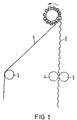
- 1 to 4 show a plant for carrying out the method according to the invention and a finished catalyst body with a greatly enlarged section thereof.
- a particular advantage of the catalyst body according to the invention is that the jacket tube necessary for its strength is coated neither with connecting nor with catalyst material. Therefore, it can be welded directly to the subsequent pipelines later without complex cleaning processes.
- a flat sheet metal strip (1) and an approximately trapezoidally corrugated sheet metal strip are wound together.
- the flat sheet metal strip (1) is passed over a deflection roller (3) and the corrugated sheet metal strip (2) is passed between two rollers (4 and 5), which coat the sheet metal strip (2) at its raised points with a liquid adhesive.
- a cavity is shown in the interior of the coiled sheet metal strips, but is actually essentially filled by coiled sheet metal strips, as will be explained later.
- the metal strips (1 and 2) are wound up as in Fig. 1, but they are each passed through two containers (6 and 7) or (8 and 9) before being wound up and coated therein with a liquid adhesive.
- the rollers (10 and 11 or 12 and 13) are used for guidance in these containers, while a deflecting roller (14 and 15) is arranged between the containers.
- radiators (16 and 17) are arranged above and below the sheet metal strip (1), for example according to the infrared principle, which dry the adhesive applied to the sheet metal strip (1).
- the sheet metal strip (2) is dried in the same way by the radiators (18 and 19).
- radiators are also expedient for drying, but they are omitted in FIG. 2 to simplify the illustration. It is within the scope of the invention if only one of the two metal strips (1 or 2) is coated or the number of containers and radiators shown is increased or decreased.
- Fig. 3 shows a completely wound catalyst body (20) consisting of the spirally wound sheet metal strips (1 and 2) and an outer, cylindrical jacket tube (21) which holds the wound sheet metal strips together.
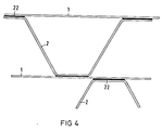
- FIG. 4 shows a greatly enlarged detail from FIG. 3, in which the metal strips (1 and 2) are connected via the adhesive (22).
- the sheet metal strips (1) are shown with straight lines. In fact, after being wound up, they have a curvature corresponding to the curvature diameter that increases from the inside to the outside during winding.
Landscapes
- Chemical & Material Sciences (AREA)
- Chemical Kinetics & Catalysis (AREA)
- Engineering & Computer Science (AREA)
- Materials Engineering (AREA)
- Organic Chemistry (AREA)
- Health & Medical Sciences (AREA)
- Toxicology (AREA)
- Combustion & Propulsion (AREA)
- Mechanical Engineering (AREA)
- General Engineering & Computer Science (AREA)
- Catalysts (AREA)
Description
- Die vorliegende Erfindung betrifft einen spiralig gewickelten Katalysatorkörper aus profilierten Blechbändern aus hochtemperaturbeständigen Werkstoffen sowie Verfahren zum Herstellen. Diese Katalysatorkörper werden mit einem Katalysatormaterial beschichtet und sind insbesondere vorgesehen für Gase bei hohen Temperaturen, beispielsweise zur Nachbehandlung von Abgasen aus Kraftfahrzeug-Verbrennungsmotoren. Katalysatorkörper zur Behandlung von Abgasen aus nicht stationären Verbrennungskraftmaschinen sollen nicht nur aus Preis- und Gewichtsgründen einen geringen Materialverbrauch haben, sondern müssen auch aus Platzgründen sehr viel Katalysatormaterial auf geringem Raum zulassen und dennoch einen ausreichenden Querschnitt für die durchtretenden Gase freilassen. Außerdem müssen sie den mechanischen Beanspruchungen standhalten, die einerseits von den ständigen Erschütterungen im Betrieb verursacht werden und andererseits von den Druckwellen, die zwangsläufig im Abgasstrom einer Verbrennungskraftmaschine gegeben sind.
- Beim Löten von sehr dünnen Blechen mit einer Wandstärke von 0,04 mm oder noch weniger traten bisher Schwierigkeiten auf, weil die üblichen Lötpasten in einem Bindemittel Lötkörper enthalten, deren Durchmesser üblicherweise 0,01 bis 0,1 mm beträgt, und die aufgetragene Schicht der Lötpaste zwangsläufig wesentlich dicker ist als der angegebene größte Durchmesser der Lötkörner. Im Bereich der zu lötenden Flächen ist daher die Materialmenge des Lötwerkstoffes wesentlich größer als die Materialmenge des angrenzenden dünnwandigen Bleches.
- Es kommt daher durch Diffusion zum Auflegieren der wesentlich geringeren Werkstoffmenge des Bleches mit der bedeutend größeren Menge des Lötmaterials an der Lötstelle, wodurch die mengenmäßig geringeren Anteile des Blechwerkstoffes sich in der mengenmäßig größeren Lötschmelze lösen und zum Ausschmelzen des dünnwandigen Bleches führen. Insbesondere bei Anhäufung mehrerer dicker Lötkörner entstehen dann im dünnwandigen Blech Löcher, die naturgemäß die örtliche Festigkeit erheblich stören. Auch wenn man die üblichen Lötpasten sehr sorgfältig und nur in einer sehr dünnen Schicht auftragen würde, so läßt sich doch nicht vermeiden, daß an Blechkanten oder in Ecken und Spalten größere Mengen an Lötpaste zurückbleiben, die ebenfalls das bereits erwähnte Schmelzen des dünnwandigen Bleches und damit Löcher an den Lötstellen bewirken, anstatt wie beabsichtigt, diese Bleche miteinander zu verbinden.
- In der deutschen Patentschrift 1 192 624 ist beschrieben »ein Verfahren zur Herstellung von Katalysatoren, bei dem man einen Grundkörper durch spiraliges Aufwickeln der aus hochtemperaturfester Legierung bestehenden Streifen bildet, mit einem gleiche Metalle wie die Legierung enthaltenden Pulver oder einer solchen Paste überzieht und dann bis zum Verschmelzen aller Kontaktstellen der aufeinanderliegenden flachen und geriffelten Streifen erhitzt und den entstandenen scheibenförmigen Körper mit einer dünnen Schicht eines Edelmetalls in bekannter Weise überzieht«. Aus den Figuren ist ersichtlich, daß ein sinus- oder dreieckförmig gewelltes Metallband zusammen mit einem flachen Metallband spiralig aufgewickelt und miteinander verlötet werden soll. Bei der Anwendung des damaligen Verfahrens auf die heutzutage gewünschten sehr dünnwandigen Bleche der vorliegenden Erfindung würden die bereits oben beschriebenen Nachteile auftreten. Als weiterer Nachteil des damaligen Verfahrens erscheint, daß das Lötmittel anscheinend auf der gesamten Blechoberfläche aufgetragen wird und damit den späteren Kontakt des Bleches mit einem Katalysatormaterial behindert. Außerdem führt die nicht begrenzte Auftragung eines Lötmittels bei den sehr dünnen Blechen der vorliegenden Erfindung zu einer erheblichen Anhäufung von Material und damit zu einer höchst unerwünschten Verringerung des freien Kanalquerschnitts.
- Aufgabe der vorliegenden Erfindung ist ein Katalysatorkörper, insbesondere zur Behandlung von Abgasen aus Verbrennungsmaschinen und geeignete Verfahren zum Herstellen. Diese Katalysatorkörper sollen in großen Stückzahlen schnell und preiswert herstellbar sein. Eine spezielle Aufgabe der vorliegenden Erfindung ist ein Katalysatorkörper aus Blechbändern, die kontinuierlich mit Verbindungsmaterial oder auch Trägermaterial für das Katalysatormaterial beschichtet und aufgewickelt werden.
- Das Verfahren nach dem ersten Anspruch benutzt einen hochtemperaturbeständigen Klebstoff auf keramischer Basis, wie er zur Zeit von verschiedenen Firmen unter der Sammelbezeichnung »Hochtemperatur-Klebstoff« angeboten wird.
- In einer besonderen Ausführung der Erfindung kann dieser Klebstoff in wässerigen oder sonstigen Suspensionen auf den erhabenen Stellen eines profilierten, z. B. gewellten Blech-Bandes, aufgetragen werden, so daß man mit Hilfe der Konzentration und durch anschließendes Trocknen nahezu jede gewünschte Schichtstärke erreichen kann. Nach dem Trocknen kann dieser Klebstoff durch Erhitzen auf mäßige Temperaturen ausgehärtet werden. Überraschenderweise verträgt ein aus sehr dünnwandigen Blechbändern gewickelter Katalysatorkörper, der mit einem solchen Klebstoff verbunden ist, die oben bereits erwähnten mechanischen Beanspruchungen. Dabei ist vermutlich von wesentlicher Bedeutung, daß die verwendeten Bleche sehr dünnwandig sind und ein sehr engmaschiges Netz bilden, so daß Temperaturunterschiede schnell ausgeglichen werden und die durch unterschiedliche Temperaturen verursachten unterschiedlichen Ausdehnungen durch geringe Verformung der dünnwandigen Bleche ausgeglichen werden. Selbst wenn einzelne Verbindungsstellen reißen sollten, haftet das Verbindungsmaterial weiterhin an den Metalloberflächen und bildet eng ineinander verzahnte Berührungsflächen, die die im wesentlichen axialen Kräfte übertragen und nicht ausweichen können, weil die spiralig aufgewickelten Blechbänder durch das äußere Mantelrohr zusammengehalten werden.
- Im dritten Anspruch wird ein Verfahren vorgeschlagen, mit dem die Blechbänder kontinuierlich und mit sorgfältig bestimmbarer Schichtdikke beschichtet werden können. Die in einem solchen Fall ebenfalls denkbaren Tauchverfahren für die bereits gewickelten Körper führen zwangsläufig zu unterschiedlichen Schichtdikken, weil insbesondere beim Austauchen an den unteren Rändern mehr flüssiges Material haften bleibt, als am oberen Ende. Beim vorliegenden Verfahren jedoch kann durch unterschiedliche Konzentrationen der flüssigen Materialien und zwischenzeitliches Trocknen der Blech-Bänder nahezu jede gewünschte Schichtdicke gleichmäßig aufgetragen werden.
- Im vierten Anspruch wird vorgeschlagen, nach dem Verfahren aus dem dritten Anspruch auch das Trägermaterial für das katalytisch wirksame Material aufzubringen. Auch hier kann man durch Behälter mit unterschiedlichen Inhalten und zwischenzeitliches Trocknen die Schichtdikke und auch die Zusammensetzung der Schicht beeinflussen.
- Im fünften Anspruch wird vorgeschlagen, ein inaktives körniges Material aufzutragen, das nur dazu dient, die spätere katalytisch wirksame Oberfläche aufzurauhen und zu vergrößern.
- Im sechsten Anspruch ist eine bereits oben beschriebene Einzelheit des Verfahrens dargestellt.
- Im Anspruch 7 sind die mit den bereits beschriebenen Verfahren erreichbaren Endprodukte dargestellt.
- Die Fig. 1 bis 4 zeigen eine Anlage zur Durchführung der erfindungsgemäßen Verfahren sowie einen fertigen Katalysatorkörper mit einem stark vergrößerten Ausschnitt daraus.
- Ein besonderer Vorteil des erfindungsgemäßen Katalysatorkörpers ist, daß das für seine Festigkeit notwendige Mantelrohr weder mit Verbindungs- noch mit Katalysatormaterial beschichtet ist. Daher kann es später ohne aufwendige Reinigungsverfahren unmittelbar mit den anschließenden Rohrleitungen verschweißt werden.
- In Fig. 1 wird ein ebenes Blechband (1) und ein etwa trapezförmig gewelltes Blechband gemeinsam aufgewickelt. Dabei wird das ebene Blechband (1) über eine Umlenkwalze (3) geleitet und das gewellte Blechband (2) zwischen zwei Walzen (4 und 5) hindurchgeleitet, die das Blechband (2) an seinen erhabenen Stellen mit einem flüssigen Klebstoff beschichten. Im Inneren der aufgewickelten Blechbänder ist ein Hohlraum dargestellt, der aber tatsächlich, wie später noch ausgeführt wird, im wesentlichen durch aufgewickelte Blechbänder ausgefüllt ist.
- In Fig. 2 werden die Blechbänder (1 und 2) wie in Fig. 1 aufgewickelt, sie werden aber vor dem Aufwickeln jeweils durch zwei Behälter (6 und 7) bzw. (8 und 9) geleitet und darin mit einem flüssigen Klebstoff beschichtet. Zur Führung in diesen Behältern dienen die Walzen (10 und 11 bzw. 12 und 13), während zwischen den Behältern jeweils eine Umlenkwalze (14 bzw. 15) angeordnet ist. Zwischen den Walzen (10 und 14) sind ober-und unterhalb des Blech-Bandes (1) Heizkörper (16 und 17), beispielsweise nach dem Infrarot-Prinzip angeordnet, die den auf dem Blechband (1) aufgetragenen Klebstoff trocknen. In gleicher Weise wird auch das Blechband (2) von den Heizkörpern (18 und 19) getrocknet. Nach dem Austritt aus den Behältern (7 und 9) sind ebenfalls Heizkörper zur Trocknung zweckmäßig, sie sind aber in der Fig. 2 zur Vereinfachung der Darstellung weggelassen. Es liegt im Rahmen der Erfindung, wenn nur eins der beiden Blechbänder (1 oder 2) beschichtet wird oder die Anzahl der dargestellten Behälter und Heizkörper vergrößert oder verringert wird.
- Fig. 3 zeigt einen fertig gewickelten Katalysatorkörper (20) bestehend aus den spiralig aufgewickelten Blechbändern (1 und 2) und einem äußeren, zylindrischen Mantelrohr (21), das die aufgewickelten Blechbänder zusammenhält.
- Fig.4 zeigt einen stark vergrößerten Ausschnitt aus Fig. 3, bei dem die Blechbänder (1 und 2) über den Klebstoff (22) verbunden sind. Aus Gründen der einfacheren Darstellung sind die Blechbänder (1) mit geraden Linien dargestellt. Tatsächlich haben sie nach dem Aufwikkeln eine Krümmung entsprechend dem beim Aufwickeln von innen nach außen zunehmenden Krümmungsdurchmesser.
Claims (7)
Priority Applications (1)
| Application Number | Priority Date | Filing Date | Title |
|---|---|---|---|
| AT81108655T ATE13493T1 (de) | 1981-01-12 | 1981-10-21 | Katalysatorkoerper. |
Applications Claiming Priority (2)
| Application Number | Priority Date | Filing Date | Title |
|---|---|---|---|
| DE19813100658 DE3100658A1 (de) | 1981-01-12 | 1981-01-12 | "katalysatorkoerper" |
| DE3100658 | 1981-01-12 |
Publications (3)
| Publication Number | Publication Date |
|---|---|
| EP0056435A2 EP0056435A2 (de) | 1982-07-28 |
| EP0056435A3 EP0056435A3 (en) | 1982-08-11 |
| EP0056435B1 true EP0056435B1 (de) | 1985-05-29 |
Family
ID=6122459
Family Applications (1)
| Application Number | Title | Priority Date | Filing Date |
|---|---|---|---|
| EP81108655A Expired EP0056435B1 (de) | 1981-01-12 | 1981-10-21 | Katalysatorkörper |
Country Status (3)
| Country | Link |
|---|---|
| EP (1) | EP0056435B1 (de) |
| AT (1) | ATE13493T1 (de) |
| DE (2) | DE3100658A1 (de) |
Cited By (3)
| Publication number | Priority date | Publication date | Assignee | Title |
|---|---|---|---|---|
| DE3831616A1 (de) * | 1988-09-17 | 1990-03-22 | Sueddeutsche Kuehler Behr | Verfahren zur herstellung von traegerkoerpern fuer katalytische reaktoren zur abgasreinigung |
| DE3833675A1 (de) * | 1988-10-04 | 1990-04-05 | Sueddeutsche Kuehler Behr | Traegerkoerper fuer einen katalytischen reaktor zur abgasreinigung |
| DE3844350A1 (de) * | 1988-12-30 | 1990-07-05 | Sueddeutsche Kuehler Behr | Traegerkoerper fuer einen katalytischen reaktor zur abgasreinigung |
Families Citing this family (8)
| Publication number | Priority date | Publication date | Assignee | Title |
|---|---|---|---|---|
| DE8438260U1 (de) * | 1984-12-29 | 1985-04-11 | Süddeutsche Kühlerfabrik Julius Fr. Behr GmbH & Co KG, 7000 Stuttgart | Traegermatrix, insbesondere fuer einen katalytischen reaktor zur abgasreinigung |
| DE3543011A1 (de) * | 1985-12-05 | 1987-06-11 | Sueddeutsche Kuehler Behr | Matrix fuer einen katalysator |
| US4711009A (en) * | 1986-02-18 | 1987-12-08 | W. R. Grace & Co. | Process for making metal substrate catalytic converter cores |
| ES2010687B3 (es) * | 1986-05-12 | 1989-12-01 | Interatom Ges Mit Beschrankter Haftung | Cuerpo alveolado metalico, especialmente cuerpo portante de catalizador con pared portante y procedimiento para su fabricacion. |
| DE8811086U1 (de) * | 1988-09-01 | 1988-10-20 | Emitec Gesellschaft für Emissionstechnologie mbH, 53797 Lohmar | Trägerkörper für einen katalytischen Reaktor zur Abgasreinigung |
| EP0659480A1 (de) * | 1993-12-27 | 1995-06-28 | SUT-SYSTEM- UND UMWELTTECHNIK GmbH | Metallischer Trägerkörper mit gesinterter Zellstruktur |
| AU669973B2 (en) * | 1994-02-08 | 1996-06-27 | Nippon Steel Corporation | Metal honeycomb for catalyst for automobiles and method of manufacturing the same |
| DE19827385A1 (de) | 1998-06-19 | 1999-12-23 | Basf Ag | Tränkverfahren zur Aufbringung von Aktivmasse auf strukturierte Träger oder Monolithe |
Family Cites Families (3)
| Publication number | Priority date | Publication date | Assignee | Title |
|---|---|---|---|---|
| US3208131A (en) * | 1961-03-22 | 1965-09-28 | Universal Oil Prod Co | Rigid catalytic metallic unit and method for the production thereof |
| US4058485A (en) * | 1974-12-26 | 1977-11-15 | Union Carbide Corporation | Porous metal-alumina composite |
| US4196099A (en) * | 1978-02-10 | 1980-04-01 | Matthey Bishop, Inc. | Catalyst comprising a metal substrate |
-
1981
- 1981-01-12 DE DE19813100658 patent/DE3100658A1/de not_active Withdrawn
- 1981-10-21 EP EP81108655A patent/EP0056435B1/de not_active Expired
- 1981-10-21 DE DE8181108655T patent/DE3170751D1/de not_active Expired
- 1981-10-21 AT AT81108655T patent/ATE13493T1/de active
Cited By (3)
| Publication number | Priority date | Publication date | Assignee | Title |
|---|---|---|---|---|
| DE3831616A1 (de) * | 1988-09-17 | 1990-03-22 | Sueddeutsche Kuehler Behr | Verfahren zur herstellung von traegerkoerpern fuer katalytische reaktoren zur abgasreinigung |
| DE3833675A1 (de) * | 1988-10-04 | 1990-04-05 | Sueddeutsche Kuehler Behr | Traegerkoerper fuer einen katalytischen reaktor zur abgasreinigung |
| DE3844350A1 (de) * | 1988-12-30 | 1990-07-05 | Sueddeutsche Kuehler Behr | Traegerkoerper fuer einen katalytischen reaktor zur abgasreinigung |
Also Published As
| Publication number | Publication date |
|---|---|
| ATE13493T1 (de) | 1985-06-15 |
| DE3100658A1 (de) | 1982-08-26 |
| DE3170751D1 (en) | 1985-07-04 |
| EP0056435A2 (de) | 1982-07-28 |
| EP0056435A3 (en) | 1982-08-11 |
Similar Documents
| Publication | Publication Date | Title |
|---|---|---|
| DE3037796C2 (de) | Verfahren zum Löten und dessen Verwendung | |
| DE4219145C1 (de) | Verfahren und Vorrichtung zum Beloten eines metallischen Wabenkörpers | |
| EP0056435B1 (de) | Katalysatorkörper | |
| DE2853023C2 (de) | Plattenförmiger Katalysator und dessen Verwendung zum Reduzieren von NO↓x↓ in einem Abgas | |
| EP0876216B1 (de) | Schichtartig aufgebaute bleche mit aufgewalztem lotmaterial und verfahren zum herstellen eines wabenkörpers daraus | |
| EP1051564B1 (de) | Verfahren zum herstellen eines ummantelten wabenkörpers | |
| DE69721326T2 (de) | Katalytischer metallwabenkörper zur abgasreinigung und dessen herstellung | |
| DE3922264C2 (de) | Aus Metall hergestellter Trägerkörper für einen Abgasreinigungskatalysator und Verfahren zu seiner Herstellung | |
| DE10200069A1 (de) | Wabenstruktur und Verfahren zu deren Beleimung und Belotung | |
| DE3843350C2 (de) | ||
| DE2222663C3 (de) | Verfahren zur Herstellung einer Vorrichtung zur Reinigung der Abgase von Brennkraftmaschinen | |
| DE4411302C1 (de) | Verfahren zur Herstellung eines beschichteten, monolithischen Trägerkatalysators | |
| EP0660768A1 (de) | Verfahren zum beloten einer metallischen struktur, insbesondere von teilbereichen eines wabenkörpers. | |
| DE3105982A1 (de) | Katalysatoraggregat | |
| EP0932471B1 (de) | Verfahren zur herstellung eines gelöteten metallischen wabenkörpers | |
| EP0741609B1 (de) | Mit zeolith beschichtbare metallische folie | |
| DE2337034A1 (de) | Hitzebestaendiges wabenfoermiges gebilde und verfahren zu dessen herstellung | |
| EP0812246B1 (de) | Wabenkörper mit nur teilweiser anbindung an ein mantelrohr | |
| DE2826843C2 (de) | ||
| EP1495215B1 (de) | Kalibrierter katalysator-trägerkörper mit wellmantel und verfahren zu dessen herstellung | |
| DE3726502C2 (de) | ||
| DE3603882A1 (de) | Verfahren zur herstellung eines metall-traegerkoerpers fuer einen konverter zur abgasreinigung und nach diesem verfahren hergestellter metall-traegerkoerper | |
| EP2191113B1 (de) | Metallische folie zur herstellung von wabenkörpern und daraus hergestellter wabenkörper | |
| DE3010997C2 (de) | Im Querschnitt elliptisches, zylindrisches, katalytisch aktives Metallsubstrat und Verfahren zu seiner Herstellung | |
| DE3608120A1 (de) | Koerper aus duennwandigem, aluminiumhaltigem edelstahl |
Legal Events
| Date | Code | Title | Description |
|---|---|---|---|
| PUAI | Public reference made under article 153(3) epc to a published international application that has entered the european phase |
Free format text: ORIGINAL CODE: 0009012 |
|
| PUAL | Search report despatched |
Free format text: ORIGINAL CODE: 0009013 |
|
| 17P | Request for examination filed |
Effective date: 19811021 |
|
| AK | Designated contracting states |
Designated state(s): AT BE CH DE FR GB IT LU NL SE |
|
| AK | Designated contracting states |
Designated state(s): AT BE CH DE FR GB IT LU NL SE |
|
| ITF | It: translation for a ep patent filed | ||
| GRAA | (expected) grant |
Free format text: ORIGINAL CODE: 0009210 |
|
| RAP1 | Party data changed (applicant data changed or rights of an application transferred) |
Owner name: INTERATOM GESELLSCHAFT MIT BESCHRAENKTER HAFTUNG |
|
| AK | Designated contracting states |
Designated state(s): AT BE CH DE FR GB IT LI LU NL SE |
|
| REF | Corresponds to: |
Ref document number: 13493 Country of ref document: AT Date of ref document: 19850615 Kind code of ref document: T |
|
| REF | Corresponds to: |
Ref document number: 3170751 Country of ref document: DE Date of ref document: 19850704 |
|
| ET | Fr: translation filed | ||
| PLBI | Opposition filed |
Free format text: ORIGINAL CODE: 0009260 |
|
| 26 | Opposition filed |
Opponent name: SUEDDEUTSCHE KUEHLERFABRIK JULIUS FR. BEHR GMBH & Effective date: 19860226 |
|
| NLR1 | Nl: opposition has been filed with the epo |
Opponent name: SUEDDEUTSCHE KUEHLERFABRIK JULIUS FR.BEHR GMBH & C |
|
| PLBM | Termination of opposition procedure: date of legal effect published |
Free format text: ORIGINAL CODE: 0009276 |
|
| STAA | Information on the status of an ep patent application or granted ep patent |
Free format text: STATUS: OPPOSITION PROCEDURE CLOSED |
|
| 27C | Opposition proceedings terminated |
Effective date: 19870727 |
|
| ITTA | It: last paid annual fee | ||
| EPTA | Lu: last paid annual fee | ||
| NLR2 | Nl: decision of opposition | ||
| EAL | Se: european patent in force in sweden |
Ref document number: 81108655.2 |
|
| PGFP | Annual fee paid to national office [announced via postgrant information from national office to epo] |
Ref country code: AT Payment date: 19961008 Year of fee payment: 16 |
|
| PGFP | Annual fee paid to national office [announced via postgrant information from national office to epo] |
Ref country code: BE Payment date: 19961017 Year of fee payment: 16 |
|
| PGFP | Annual fee paid to national office [announced via postgrant information from national office to epo] |
Ref country code: NL Payment date: 19961024 Year of fee payment: 16 |
|
| PGFP | Annual fee paid to national office [announced via postgrant information from national office to epo] |
Ref country code: LU Payment date: 19961031 Year of fee payment: 16 |
|
| PGFP | Annual fee paid to national office [announced via postgrant information from national office to epo] |
Ref country code: CH Payment date: 19970117 Year of fee payment: 16 |
|
| PG25 | Lapsed in a contracting state [announced via postgrant information from national office to epo] |
Ref country code: LU Free format text: LAPSE BECAUSE OF NON-PAYMENT OF DUE FEES Effective date: 19971021 Ref country code: AT Free format text: LAPSE BECAUSE OF NON-PAYMENT OF DUE FEES Effective date: 19971021 |
|
| PG25 | Lapsed in a contracting state [announced via postgrant information from national office to epo] |
Ref country code: LI Free format text: LAPSE BECAUSE OF NON-PAYMENT OF DUE FEES Effective date: 19971031 Ref country code: CH Free format text: LAPSE BECAUSE OF NON-PAYMENT OF DUE FEES Effective date: 19971031 Ref country code: BE Free format text: LAPSE BECAUSE OF NON-PAYMENT OF DUE FEES Effective date: 19971031 |
|
| BERE | Be: lapsed |
Owner name: INTERATOM G.M.B.H. Effective date: 19971031 |
|
| PG25 | Lapsed in a contracting state [announced via postgrant information from national office to epo] |
Ref country code: NL Free format text: LAPSE BECAUSE OF NON-PAYMENT OF DUE FEES Effective date: 19980501 |
|
| REG | Reference to a national code |
Ref country code: CH Ref legal event code: PL |
|
| NLV4 | Nl: lapsed or anulled due to non-payment of the annual fee |
Effective date: 19980501 |
|
| PGFP | Annual fee paid to national office [announced via postgrant information from national office to epo] |
Ref country code: GB Payment date: 19980909 Year of fee payment: 18 |
|
| PGFP | Annual fee paid to national office [announced via postgrant information from national office to epo] |
Ref country code: FR Payment date: 19981023 Year of fee payment: 18 |
|
| PGFP | Annual fee paid to national office [announced via postgrant information from national office to epo] |
Ref country code: SE Payment date: 19981027 Year of fee payment: 18 |
|
| PG25 | Lapsed in a contracting state [announced via postgrant information from national office to epo] |
Ref country code: GB Free format text: LAPSE BECAUSE OF NON-PAYMENT OF DUE FEES Effective date: 19991021 |
|
| PG25 | Lapsed in a contracting state [announced via postgrant information from national office to epo] |
Ref country code: SE Free format text: THE PATENT HAS BEEN ANNULLED BY A DECISION OF A NATIONAL AUTHORITY Effective date: 19991030 |
|
| PGFP | Annual fee paid to national office [announced via postgrant information from national office to epo] |
Ref country code: DE Payment date: 19991129 Year of fee payment: 19 |
|
| GBPC | Gb: european patent ceased through non-payment of renewal fee |
Effective date: 19991021 |
|
| EUG | Se: european patent has lapsed |
Ref document number: 81108655.2 |
|
| PG25 | Lapsed in a contracting state [announced via postgrant information from national office to epo] |
Ref country code: FR Free format text: LAPSE BECAUSE OF NON-PAYMENT OF DUE FEES Effective date: 20000630 |
|
| REG | Reference to a national code |
Ref country code: FR Ref legal event code: ST |
|
| PG25 | Lapsed in a contracting state [announced via postgrant information from national office to epo] |
Ref country code: DE Free format text: LAPSE BECAUSE OF NON-PAYMENT OF DUE FEES Effective date: 20010703 |