EP0055548A1 - Arrangement de roulement - Google Patents
Arrangement de roulement Download PDFInfo
- Publication number
- EP0055548A1 EP0055548A1 EP81305891A EP81305891A EP0055548A1 EP 0055548 A1 EP0055548 A1 EP 0055548A1 EP 81305891 A EP81305891 A EP 81305891A EP 81305891 A EP81305891 A EP 81305891A EP 0055548 A1 EP0055548 A1 EP 0055548A1
- Authority
- EP
- European Patent Office
- Prior art keywords
- bore
- sleeve
- outer race
- chamber
- block
- Prior art date
- Legal status (The legal status is an assumption and is not a legal conclusion. Google has not performed a legal analysis and makes no representation as to the accuracy of the status listed.)
- Granted
Links
Images


Classifications
-
- F—MECHANICAL ENGINEERING; LIGHTING; HEATING; WEAPONS; BLASTING
- F16—ENGINEERING ELEMENTS AND UNITS; GENERAL MEASURES FOR PRODUCING AND MAINTAINING EFFECTIVE FUNCTIONING OF MACHINES OR INSTALLATIONS; THERMAL INSULATION IN GENERAL
- F16C—SHAFTS; FLEXIBLE SHAFTS; ELEMENTS OR CRANKSHAFT MECHANISMS; ROTARY BODIES OTHER THAN GEARING ELEMENTS; BEARINGS
- F16C33/00—Parts of bearings; Special methods for making bearings or parts thereof
- F16C33/30—Parts of ball or roller bearings
- F16C33/66—Special parts or details in view of lubrication
- F16C33/6637—Special parts or details in view of lubrication with liquid lubricant
- F16C33/6659—Details of supply of the liquid to the bearing, e.g. passages or nozzles
-
- F—MECHANICAL ENGINEERING; LIGHTING; HEATING; WEAPONS; BLASTING
- F16—ENGINEERING ELEMENTS AND UNITS; GENERAL MEASURES FOR PRODUCING AND MAINTAINING EFFECTIVE FUNCTIONING OF MACHINES OR INSTALLATIONS; THERMAL INSULATION IN GENERAL
- F16C—SHAFTS; FLEXIBLE SHAFTS; ELEMENTS OR CRANKSHAFT MECHANISMS; ROTARY BODIES OTHER THAN GEARING ELEMENTS; BEARINGS
- F16C19/00—Bearings with rolling contact, for exclusively rotary movement
- F16C19/02—Bearings with rolling contact, for exclusively rotary movement with bearing balls essentially of the same size in one or more circular rows
- F16C19/14—Bearings with rolling contact, for exclusively rotary movement with bearing balls essentially of the same size in one or more circular rows for both radial and axial load
- F16C19/16—Bearings with rolling contact, for exclusively rotary movement with bearing balls essentially of the same size in one or more circular rows for both radial and axial load with a single row of balls
- F16C19/163—Bearings with rolling contact, for exclusively rotary movement with bearing balls essentially of the same size in one or more circular rows for both radial and axial load with a single row of balls with angular contact
-
- F—MECHANICAL ENGINEERING; LIGHTING; HEATING; WEAPONS; BLASTING
- F16—ENGINEERING ELEMENTS AND UNITS; GENERAL MEASURES FOR PRODUCING AND MAINTAINING EFFECTIVE FUNCTIONING OF MACHINES OR INSTALLATIONS; THERMAL INSULATION IN GENERAL
- F16C—SHAFTS; FLEXIBLE SHAFTS; ELEMENTS OR CRANKSHAFT MECHANISMS; ROTARY BODIES OTHER THAN GEARING ELEMENTS; BEARINGS
- F16C25/00—Bearings for exclusively rotary movement adjustable for wear or play
- F16C25/06—Ball or roller bearings
- F16C25/08—Ball or roller bearings self-adjusting
-
- F—MECHANICAL ENGINEERING; LIGHTING; HEATING; WEAPONS; BLASTING
- F16—ENGINEERING ELEMENTS AND UNITS; GENERAL MEASURES FOR PRODUCING AND MAINTAINING EFFECTIVE FUNCTIONING OF MACHINES OR INSTALLATIONS; THERMAL INSULATION IN GENERAL
- F16C—SHAFTS; FLEXIBLE SHAFTS; ELEMENTS OR CRANKSHAFT MECHANISMS; ROTARY BODIES OTHER THAN GEARING ELEMENTS; BEARINGS
- F16C2322/00—Apparatus used in shaping articles
- F16C2322/39—General build up of machine tools, e.g. spindles, slides, actuators
Definitions
- the present invention relates in general to , bearing arrangements and more particularly to bearing units usable with the spindles of machine tools and capable of subjecting a bearing thereof to an adjustable axial pre-load force.
- the present invention seeks to overcome various disadvantages which are encountered with the prior arrangements. More particularly, the invention seeks to provide a compact self-contained unit which can be easily fitted as a replacement for one of the bearing arrangements for the spindle of an existing machine tool.
- the present invention provides a self-contained bearing unit for direct location in a bore of a housing wall of a machine tool to supplement another bearing or bearings in rotatably supporting a spindle.
- the unit comprises an angular-contact ball bearing with inner and outer races. Passages or the like permit lubricant to be conveyed to the bearing.
- the inner race of the bearing is fixedly rotatable with the spindle while the outer race is restrained against rotation but axial displacement thereof relative to the inner race is permitted.
- An annular chamber is defined independent of the bore in the housing wall. In one aspect of the invention, pressure fluid is conveyed to said chamber, and a resiliently deformable annular U-shaped seal is provided in the chamber.
- the seal is then subjected directly to the pressure fluid conveyed to the chamber which exerts an axial displacement force on the outer race to pre-load the bearing.
- an annular resilient bellows device can be disposed in the chamber. Pressure fluid can then be conveyed into the bellows device to exert an axial displacement force on the outer race to pre-load the bearing.
- the dynamic stiffness of the associated tool spindle can be improved and further benefits can result by controlled adjustment of the axial pre-load force by hydraulic means.
- the U-shaped seal can be made from a low friction plastics liner and spring steel. Such a seal can be moved to form an annular thrust piston which is overall deformably resilient or else such a seal can remain stationary and is used to create a reaction force to displace the outer bearing race.
- an annular thrust piston which is overall deformably resilient or else such a seal can remain stationary and is used to create a reaction force to displace the outer bearing race.
- one end ring for example would remain stationary while another end ring moves outwardly therefrom by the resilient expansion of a concertina-like annular piece therebetween. The movement of the other end ring can then produce thrust or reaction force.
- Both resilient components can provide inherent damping although-a restriction in the pressure fluid flow path is useful to enhance this effect.
- a sleeve or annular block may contain the bearing and be received in the machine tool housing wall bore. It is however, possible to locate the outer bearing race directly in this bore.
- the chamber which receives pressure fluid or which contains the bellows device which receives pressure fluid may be disposed within the bore, preferably in the sleeve, or externally thereof.
- the sleeve and/or block may contain separate bores through which the pressure fluid and the lubricant is passed. Radial or axial end face openings can provide access to these bores.
- the unit is especially compact smaller or not larger in width than the housing wall bore in which it is fitted and considerably smaller than the axial dimension of the spindle.
- the headstock of a machine tool for example, includes a housing with front and rear walls 1, 2 respectively.
- a tool spindle 3 is supported for rotation in the housing by means of an angular-contact ball bearing assembly 4 of conventional type and by a bearing unit 5 constructed in accordance with the invention.
- the assembly 4 composed of two side-by-side bearings, is mounted in the front wall 1 while the unit 5 is mounted in the rear wall 2.
- the unit 5 is fitted directly into a bore 51 or hole in the wall 2 and engages on a retention ring 6 therein.
- the unit 5 is entirely self-contained and can be used in various different overall application and constructions requiring variable axial pre-load of which Tigure 1 is merely illustrative.
- the unit 5 is composed of an external sleeve 7 made from hardened .bearing steel, containing an angular-contact ball bearing with inner and outer races 8,9, balls 10 and a cage (not shown).
- the inner race 8 which rotates with the spindle 3, is extended in width in relation to the outer race 9 and as illustrated the inner race 8 extends the whole width of the unit 5.
- the outer race 9 and the sleeve 7 are relatively displaceable in a direction parallel to the axis of the spindle 3 and a sliding contact is established between the external surface of the race 9 and the interior surface of,the sleeve 7.
- a screw 21 in the sleeve 7 engages in an axial slot 25 in the race 9.
- An annular block 11 is also received in the sleeve 7 and a ring 12 fitted into a groove in the interior surface of the sleeve 7 serves to retain the block 11 in the sleeve 7.
- a recess 23 is formed at the end of the block 11 remote from the ring 12 adjacent the interior of the sleeve 7. This recess 23 partly defines a pressure fluid-reception chamber 24. Bores 15, 15', 16 in the sleeve 7 serve to permit fluid to be conveyed to and from the chamber 24.
- the radial bore 16 leading to the chamber 24 communicates with a longitudinal or axial bore 15 and a radial bore 15'. This permits the fluid to be supplied from the radial or axial exterior of the unit 5 and the bore 15, 15' not used can serve to bleed the chamber 24 or can be blocked off.
- the radial bore 16 is smaller in cross-section than the bores 15, 15' to provide a restriction to fluid flow.
- a displaceable resilient, annular seal 13 is disposed in the chamber 24.
- the seal 13 can be made from a suitable plastics material, e.g. PTFE, with a shaped spring steel insert therein or a spring steel component lined with such material.
- the seal 13 contacts the inner end face 40 of the race 9 and the seal 13 has a U-shaped cross-section open to receive fluid in the chamber 24.
- the limbs of the seal 13 are biased into sliding sealing contact with the inner axial surfaces of the sleeve 7 and the recess 23.
- the seal 13 may be of the type know as a "Shamban Vari-seal”.
- a fixed seal 14, such as an O ring or a seal of the type known as "Shamban Quad Ring” is located in a groove in the outer surface of the block 11 to seal against the interior of the sleeve 7.
- the block 11 also contains bores 19, 20 which serve to convey lubricant to the bearing 8, 9, via a nozzle 17.
- An additional bore or bores in the sleeve 7 (not shown but similar to the bores 15, 15', 16) can supply the lubricant to the bores 19, 20.
- Figure 3 shows the details indicated by the circle D in Figure 2. As shown is Figure 3, 0-rings 22 locate in a recess 68 in the block 11 to establish a seal between the lubricant supply bores of the sleeve 7 and the block 11.
- Figures 4 and 5 depict another unit with the bearing races 8, 9 of standard equal width.
- a thrust ring 27 is positioned between the seal 13 and the outer race 9.
- the block 11 does not lie wholly within the sleeve 7 and moreover the block 11 is provided with a flange 28 which abuts a chamfered end 29 of the outer sleeve 7.
- the ring 12 is hence omitted.
- the sleeve 7 is also provided with a flange 30 as the opposite end which serves to locate the sleeve 7 in the bore 51 in the housing wall 2.
- the grub screw 21 which locks the sleeve 7 to the race 9 in the rotational sense here engages in a recess 31 extending from the outer end face of - the race 9.
- the unit 5 shown in Figures 4 and 5 also employs a somewhat different form of lubrication and fluid supply system.
- the lubricant is supplied via a U-shaped path composed of a longitudinal bore 32 and a radial bore 33 in the sleeve 7 and a radial bore 34 and a longitudinal bore 35 in.the block 11 and thence to the nozzle 17.
- the pressure fluid for axially displacing the race 9 is conveyed via the logitudinal bore 15 and the smaller radial bore 16 in the sleeve as before.
- the fluid admitted to the chamber 24 displaces the seal 13 and exerts an outward thrust-force directly on the bearing race 9.
- the fluid admitted to the chamber 24 provides a reactive force which displaces the race 9.
- the block 11 has a significant cylindrical axial region 38 positioned between the sleeve 7 and the race 9 and extending outwardly beyond the flange 30 locating the sleeve 7 to the house wall 2.
- the block 11 has a radically-inwardly projecting flange 39 which engages the inner end face 40 of the race 9 and lies between the face 40 and a radial flange 34 of the sleeve 7.
- the chamber 24 is positioned outside the sleeve 7 and the housing wall 2.
- a further component 41 which could be integral with the block 11, defines the chamber 24 in conjunction with the axial region 38 of the block 11 and an axial projection 42 of the sleeve 7.
- the component 41 has a radial end wall 47 acting as a shield. Sliding contact is established between the outer surfaces 43 of the region 38 of the block 11 and the inner surface 44 of the sleeve 7. The inner surface of the region 38 of the block 11 can make tight contact with the race 9 to restrain rotation. Further sliding contact is established between the outer surface 45 of the sleeve projection 42 and the inner surface . 46 of the component 41.
- a coupling 47 mounted to the component.41 serves to convey pressure fluid directly to the chamber 24.
- Lubricant is supplied via a channel 48 in the wall 2 and complementary.bores 49 in the sleeve 7 to the bearing 8, 9 as well as to the sliding surfaces 43, 44.
- An 0-ring 50 in the outer surface of the sleeve 7 seals against the surface of the bore 51 in the housing wall 2.
- the block 11 moves with the race 9. More particularly, pressure fluid supplied to the chamber 24 reacts against the resilient seal 13 to urge the block 11 and the race 9 in the direction of arrow A.
- the relatively long sliding surfaces 43, 44 and the sliding surfaces 45, 46 provide adequate guidance for the displacement.
- the sleeve 7 is replaced by a ring 52 resembling just the outer region 30, 42 of the sleeve 7 of Figure 6 and the outer surface 43 of the axial region 38 is now in sliding contact with the surface of the bore 51 in the wall 2.
- the lubricant is again supplied via the channel 48 in the wall 2 but the lubricant enters a recess 53 in the surface 43 of the region 38 of the block 11 and flows through bores 54 in a stepped end flange 55 of the 11 to reach the bearing 8, 9.
- the - 0-ring 50 is now provided in the outer surface of this end flange 55 to engage with the surface of the bore 51.
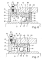
- Figure 8 depicts another unit which employs a pair of angular contact ball bearing 8,8',9,9' ,10,10' mounted side-by-side.
- the outer races 9, 9' are locked against rotation by the annular block 11 while the inner races 8, 8' rotate with the spindle 3.
- the block 11 again makes sliding contact with the bore 51 in the housing wall 2.
- the sliding surfaces can also be keyed.
- the lub cation supply system may be as described in connection with Figure 7.
- the block 11 has a screw-threaded external portion 56 which receives a screw-threaded ring 57 defining the chamber 24 with a further component 41 fitted to the wall 2.
- the seal 13 abuts directly on the wall 2. Provision is made to lock the ring 57 in its rotational position while permitting axial displacement.
- a series of spaced peripheral slots 58 in the ring 57 permits such locking with a screw 59 detachably fixed to the wall 2 and engaging through a keyway in the component 41.
- fluid supplied to the chamber 24 via a coupling 47 on the ring reacts against the seal 13 to move the ring 57 and the block 11 and the outer bearing races 9, 9' in the direction of arrow A.
- Figure 9 depicts a simplified form of unit which again utilises the adjustment ring 57 but in this construction the ring 57 is in screw-threaded engagement with an extended outer race 9 of the bearing.
- This race 9 is in direct sliding contact with the bore 51 and lubricant can be supplied to the bearing via the channel 48, recess 53 and bore 49.
- a grub screw 21 accessible from the wall 2 engages in a slot or recess 31 in the race 9 as described hereinbefore.
- the ring 57 can be restrained from rotation in the manner shown in Figure 8.
- FIG. 10 shows annular bellows device 60 with a concertina-like expandible resilient annular centre section 61 between two end rings 62. Access to the interior of the section 61 is by way of a port or conduit 63 provided on one of the rings 62.
- the bellows 60 could be mounted in the chamber 24 in the embodiments of the invention described and illustrated. In contrast however, the pressure fluid would be admitted to the interior of the section 61 rather than to the chamber 24 itself to force end rings 61 apart.
- the bellows 60 can produce thrust force (Figs. 1 to 5) or reactive force (Figs 6 to 9) to displace the race 9.
Applications Claiming Priority (2)
| Application Number | Priority Date | Filing Date | Title |
|---|---|---|---|
| GB8040143 | 1980-12-15 | ||
| GB8040143 | 1980-12-15 |
Publications (2)
| Publication Number | Publication Date |
|---|---|
| EP0055548A1 true EP0055548A1 (fr) | 1982-07-07 |
| EP0055548B1 EP0055548B1 (fr) | 1986-01-22 |
Family
ID=10518003
Family Applications (1)
| Application Number | Title | Priority Date | Filing Date |
|---|---|---|---|
| EP81305891A Expired EP0055548B1 (fr) | 1980-12-15 | 1981-12-15 | Arrangement de roulement |
Country Status (4)
| Country | Link |
|---|---|
| US (1) | US4400098A (fr) |
| EP (1) | EP0055548B1 (fr) |
| JP (1) | JPS57127122A (fr) |
| DE (1) | DE3173590D1 (fr) |
Cited By (6)
| Publication number | Priority date | Publication date | Assignee | Title |
|---|---|---|---|---|
| EP0214505A2 (fr) * | 1985-09-09 | 1987-03-18 | Cincinnati Milacron Inc. | Systèmes de support de broche |
| GB2183736A (en) * | 1985-11-26 | 1987-06-10 | Mtu Friedrichshafen Gmbh | A turbocharger bearing load adjustment |
| EP0459490A1 (fr) * | 1990-05-31 | 1991-12-04 | Baumüller Nürnberg Gmbh | Machine électrique avec palier fixe-libre |
| FR2665935A1 (fr) * | 1990-08-17 | 1992-02-21 | Torrington Co | Appareil a arbre monte dans un palier a charge variable, et procede d'application d'une charge a un palier. |
| EP2538100A1 (fr) * | 2011-06-22 | 2012-12-26 | Siemens Aktiengesellschaft | Dispositif de réglage pour montage de palier et agencement de palier doté d'un tel dispositif |
| CN105057709A (zh) * | 2015-09-18 | 2015-11-18 | 淄博元绪冶金机械有限公司 | 数控立铣卧镗主轴箱 |
Families Citing this family (20)
| Publication number | Priority date | Publication date | Assignee | Title |
|---|---|---|---|---|
| US4519734A (en) * | 1982-06-22 | 1985-05-28 | Ex-Cello-O Corporation | High speed spindle with preloaded bearings |
| US4527911A (en) * | 1983-04-22 | 1985-07-09 | United Technologies Corporation | Lubrication system |
| US4551032A (en) * | 1984-07-16 | 1985-11-05 | The Cross Company | Mechanism for pre-loading bearings |
| JPS61211519A (ja) * | 1985-03-13 | 1986-09-19 | Nissan Motor Co Ltd | タ−ボチヤ−ジヤの軸受構造 |
| US4657412A (en) * | 1985-03-25 | 1987-04-14 | The Torrington Company | Variable preload bearing assembly |
| US4626111A (en) * | 1985-07-25 | 1986-12-02 | Farrel Corporation | Self-compensating anti-friction bearing clearance device |
| FR2616089B1 (fr) * | 1987-06-04 | 1994-04-29 | Clecim Sa | Dispositif de maintien axial d'un cylindre a enveloppe tournante |
| US5086560A (en) * | 1990-01-24 | 1992-02-11 | Glazier Stephen C | Method of assembling prestressed frictionless bearings |
| USRE34310E (en) * | 1990-08-17 | 1993-07-13 | The Torrington Company | Variable preload bearing apparatus |
| US5739607A (en) * | 1994-03-04 | 1998-04-14 | Cincinnati Milacron Inc. | Hybrid spindle bearing |
| EP1174629A1 (fr) | 2000-06-30 | 2002-01-23 | Techspace Aero S.A. | Dispositif d'étanchéité d'un "squeeze film" intégré dans un palier à roulement |
| EP1167788A1 (fr) * | 2000-06-30 | 2002-01-02 | Techspace Aero S.A. | Dispositif d'étanchéité d'un "squeeze film" intégré dans un palier à roulement |
| EP1170520A3 (fr) * | 2000-06-30 | 2003-09-17 | Techspace Aero S.A. | Palier de roulement muni d'un amortisseur de type "squeeze film" |
| US6443698B1 (en) * | 2001-01-26 | 2002-09-03 | General Electric Company | Method and apparatus for centering rotor assembly damper bearings |
| US7384199B2 (en) * | 2004-08-27 | 2008-06-10 | General Electric Company | Apparatus for centering rotor assembly bearings |
| US7625121B2 (en) * | 2005-09-28 | 2009-12-01 | Elliott Company | Bearing assembly and centering support structure therefor |
| EP2085626B1 (fr) * | 2006-11-13 | 2013-08-21 | JTEKT Corporation | Palier à roulement et dispositif de palier à roulement |
| JP5584831B2 (ja) * | 2011-10-19 | 2014-09-03 | 三菱電機株式会社 | 車両用交流発電機 |
| US10215052B2 (en) * | 2017-03-14 | 2019-02-26 | Pratt & Whitney Canada Corp. | Inter-shaft bearing arrangement |
| CN109986095A (zh) * | 2019-04-09 | 2019-07-09 | 贾有华 | 一种机械精密机床的动力旋转轴 |
Citations (16)
| Publication number | Priority date | Publication date | Assignee | Title |
|---|---|---|---|---|
| GB341820A (en) * | 1930-03-07 | 1931-01-22 | Karl Jung | Improvements in or relating to ball bearings |
| US3025646A (en) * | 1960-11-30 | 1962-03-20 | Earl A Thompson | Spindle |
| GB1001334A (en) * | 1963-04-18 | 1965-08-18 | Skf Svenska Kullagerfab Ab | Improvements in or relating to rolling bearings |
| US3211060A (en) * | 1963-12-11 | 1965-10-12 | Giddings & Lewis | Spindle bearing preload assembly |
| US3222991A (en) * | 1964-05-22 | 1965-12-14 | Cincinnati Milling Machine Co | Bearing preload mechanism for machine tool |
| CH434892A (fr) * | 1963-07-16 | 1967-04-30 | Toyota Koki Kabushiki Kaisha | Dispositif pour appliquer une précharge à un roulement d'un arbre tournant de machine |
| FR1579285A (fr) * | 1967-09-08 | 1969-08-22 | ||
| FR1595379A (fr) * | 1968-02-23 | 1970-06-08 | ||
| GB1208133A (en) * | 1967-03-09 | 1970-10-07 | Rotax Ltd | Bearing assemblies for rotary shafts |
| US3664718A (en) * | 1970-09-21 | 1972-05-23 | Heald Machine Co | Toolhead |
| FR2113200A5 (fr) * | 1970-10-26 | 1972-06-23 | Defibrator Ab | |
| GB1312587A (en) * | 1970-02-12 | 1973-04-04 | Giddings & Lewis | Preload spindle bearing for machine tool |
| GB1421751A (en) * | 1972-04-06 | 1976-01-21 | Boneham Turner Ltd | Machine tool spindle assembly |
| US4023868A (en) * | 1975-05-13 | 1977-05-17 | Koyo Seiko Company, Limited | Bearing device |
| US4033645A (en) * | 1976-04-26 | 1977-07-05 | Koyo Seiko Company, Limited | Bearing device |
| US4116506A (en) * | 1976-04-30 | 1978-09-26 | Seiko Seiki Kabushiki Kaisha | Preloaded bearing |
Family Cites Families (4)
| Publication number | Priority date | Publication date | Assignee | Title |
|---|---|---|---|---|
| US3756672A (en) * | 1972-05-24 | 1973-09-04 | United Aircraft Corp | Shaft damping arrangement |
| US3782793A (en) * | 1973-01-24 | 1974-01-01 | Hoesch Werke Ag | Bearing construction |
| JPS5171444A (ja) * | 1974-12-18 | 1976-06-21 | Koyo Seiko Co | Yoatsuchoseigatajikukesochi |
| DE2728186A1 (de) * | 1977-06-23 | 1979-01-04 | Louis Pohl | Dreipunkt-kugellageranordnung |
-
1981
- 1981-12-11 US US06/329,881 patent/US4400098A/en not_active Expired - Lifetime
- 1981-12-15 EP EP81305891A patent/EP0055548B1/fr not_active Expired
- 1981-12-15 DE DE8181305891T patent/DE3173590D1/de not_active Expired
- 1981-12-15 JP JP56201055A patent/JPS57127122A/ja active Granted
Patent Citations (16)
| Publication number | Priority date | Publication date | Assignee | Title |
|---|---|---|---|---|
| GB341820A (en) * | 1930-03-07 | 1931-01-22 | Karl Jung | Improvements in or relating to ball bearings |
| US3025646A (en) * | 1960-11-30 | 1962-03-20 | Earl A Thompson | Spindle |
| GB1001334A (en) * | 1963-04-18 | 1965-08-18 | Skf Svenska Kullagerfab Ab | Improvements in or relating to rolling bearings |
| CH434892A (fr) * | 1963-07-16 | 1967-04-30 | Toyota Koki Kabushiki Kaisha | Dispositif pour appliquer une précharge à un roulement d'un arbre tournant de machine |
| US3211060A (en) * | 1963-12-11 | 1965-10-12 | Giddings & Lewis | Spindle bearing preload assembly |
| US3222991A (en) * | 1964-05-22 | 1965-12-14 | Cincinnati Milling Machine Co | Bearing preload mechanism for machine tool |
| GB1208133A (en) * | 1967-03-09 | 1970-10-07 | Rotax Ltd | Bearing assemblies for rotary shafts |
| FR1579285A (fr) * | 1967-09-08 | 1969-08-22 | ||
| FR1595379A (fr) * | 1968-02-23 | 1970-06-08 | ||
| GB1312587A (en) * | 1970-02-12 | 1973-04-04 | Giddings & Lewis | Preload spindle bearing for machine tool |
| US3664718A (en) * | 1970-09-21 | 1972-05-23 | Heald Machine Co | Toolhead |
| FR2113200A5 (fr) * | 1970-10-26 | 1972-06-23 | Defibrator Ab | |
| GB1421751A (en) * | 1972-04-06 | 1976-01-21 | Boneham Turner Ltd | Machine tool spindle assembly |
| US4023868A (en) * | 1975-05-13 | 1977-05-17 | Koyo Seiko Company, Limited | Bearing device |
| US4033645A (en) * | 1976-04-26 | 1977-07-05 | Koyo Seiko Company, Limited | Bearing device |
| US4116506A (en) * | 1976-04-30 | 1978-09-26 | Seiko Seiki Kabushiki Kaisha | Preloaded bearing |
Cited By (11)
| Publication number | Priority date | Publication date | Assignee | Title |
|---|---|---|---|---|
| EP0214505A2 (fr) * | 1985-09-09 | 1987-03-18 | Cincinnati Milacron Inc. | Systèmes de support de broche |
| EP0214505A3 (en) * | 1985-09-09 | 1987-05-27 | Cincinnati Milacron Inc. | Spindle support systems |
| GB2183736A (en) * | 1985-11-26 | 1987-06-10 | Mtu Friedrichshafen Gmbh | A turbocharger bearing load adjustment |
| GB2183736B (en) * | 1985-11-26 | 1989-11-15 | Mtu Friedrichshafen Gmbh | A turbocharger |
| EP0459490A1 (fr) * | 1990-05-31 | 1991-12-04 | Baumüller Nürnberg Gmbh | Machine électrique avec palier fixe-libre |
| FR2665935A1 (fr) * | 1990-08-17 | 1992-02-21 | Torrington Co | Appareil a arbre monte dans un palier a charge variable, et procede d'application d'une charge a un palier. |
| EP2538100A1 (fr) * | 2011-06-22 | 2012-12-26 | Siemens Aktiengesellschaft | Dispositif de réglage pour montage de palier et agencement de palier doté d'un tel dispositif |
| WO2012175364A1 (fr) * | 2011-06-22 | 2012-12-27 | Siemens Aktiengesellschaft | Ensemble palier permettant de loger un palier |
| CN103635709A (zh) * | 2011-06-22 | 2014-03-12 | 西门子公司 | 用于安置轴承的轴承装置 |
| CN103635709B (zh) * | 2011-06-22 | 2016-03-02 | 西门子公司 | 用于安置轴承的轴承装置 |
| CN105057709A (zh) * | 2015-09-18 | 2015-11-18 | 淄博元绪冶金机械有限公司 | 数控立铣卧镗主轴箱 |
Also Published As
| Publication number | Publication date |
|---|---|
| EP0055548B1 (fr) | 1986-01-22 |
| US4400098A (en) | 1983-08-23 |
| JPH028166B2 (fr) | 1990-02-22 |
| JPS57127122A (en) | 1982-08-07 |
| DE3173590D1 (en) | 1986-03-06 |
Similar Documents
| Publication | Publication Date | Title |
|---|---|---|
| US4400098A (en) | Bearing arrangements | |
| US4230324A (en) | Device for sealing an annular opening between a shaft and housing surrounding the shaft | |
| US7597360B2 (en) | Fluid coolant union | |
| US4641978A (en) | Bearing system | |
| US5168767A (en) | Compact ball screw assembly | |
| US3716280A (en) | Bearing construction with preload compensation | |
| CA2014558C (fr) | Raccord-union avec joint d'etancheite active par fluide, pour reseau de frigorigene | |
| US4928997A (en) | Rotating union with carbon graphite labyrinthine seal | |
| EP0349574B1 (fr) | Machine a rotors helicoidaux | |
| US4294454A (en) | Rotary seal unit | |
| US5052694A (en) | Hydrostatic face seal and bearing | |
| US3724494A (en) | Flow regulating valve | |
| GB2270724A (en) | Machine tools | |
| US4636095A (en) | Hydrodynamic plain bearing | |
| US4033645A (en) | Bearing device | |
| US5145262A (en) | Compact ball spline bearing assembly | |
| US4192559A (en) | Rotary union | |
| US4158394A (en) | Mechanism for lubricating the bearings of the cutting rollers of a roller bit | |
| US3598187A (en) | Turbodrill | |
| GB2107002A (en) | Journal bearing | |
| US5083649A (en) | Clutch release mechanism | |
| US5716142A (en) | Radial journal bearing with slide shoe | |
| GB2261037A (en) | Rolling bearing seal | |
| HU218196B (hu) | Forgó görgős fúrólyuktágító | |
| US3771803A (en) | Device for feeding pressure fluid from a stationary pressure source into a rotating member |
Legal Events
| Date | Code | Title | Description |
|---|---|---|---|
| PUAI | Public reference made under article 153(3) epc to a published international application that has entered the european phase |
Free format text: ORIGINAL CODE: 0009012 |
|
| AK | Designated contracting states |
Designated state(s): CH DE FR GB IT LI SE |
|
| 17P | Request for examination filed |
Effective date: 19821130 |
|
| RAP1 | Party data changed (applicant data changed or rights of an application transferred) |
Owner name: RHP GROUP PLC |
|
| ITF | It: translation for a ep patent filed |
Owner name: CALVANI SALVI E VERONELLI S.R.L. |
|
| GRAA | (expected) grant |
Free format text: ORIGINAL CODE: 0009210 |
|
| AK | Designated contracting states |
Designated state(s): CH DE FR GB IT LI SE |
|
| REF | Corresponds to: |
Ref document number: 3173590 Country of ref document: DE Date of ref document: 19860306 |
|
| ET | Fr: translation filed | ||
| PLBI | Opposition filed |
Free format text: ORIGINAL CODE: 0009260 |
|
| 26 | Opposition filed |
Opponent name: SKF GMBH Effective date: 19860813 |
|
| REG | Reference to a national code |
Ref country code: FR Ref legal event code: TP |
|
| REG | Reference to a national code |
Ref country code: CH Ref legal event code: PUE Owner name: AJB INDUSTRIES LIMITED, BASINGHALL STREET 35, LOND Ref country code: CH Ref legal event code: PFA Free format text: UNITED PRECISION INDUSTRIES LIMITED |
|
| REG | Reference to a national code |
Ref country code: FR Ref legal event code: TP Ref country code: FR Ref legal event code: CD |
|
| PG25 | Lapsed in a contracting state [announced via postgrant information from national office to epo] |
Ref country code: SE Effective date: 19891216 |
|
| RDAG | Patent revoked |
Free format text: ORIGINAL CODE: 0009271 |
|
| STAA | Information on the status of an ep patent application or granted ep patent |
Free format text: STATUS: PATENT REVOKED |
|
| REG | Reference to a national code |
Ref country code: CH Ref legal event code: PL |
|
| 27W | Patent revoked |
Effective date: 19900304 |
|
| GBPR | Gb: patent revoked under art. 102 of the ep convention designating the uk as contracting state | ||
| EUG | Se: european patent has lapsed |
Ref document number: 81305891.4 Effective date: 19900829 |