EP0055367B1 - Vorkompensierte Kathodenstrahlanzeigeeinrichtung für Vektoren - Google Patents
Vorkompensierte Kathodenstrahlanzeigeeinrichtung für Vektoren Download PDFInfo
- Publication number
- EP0055367B1 EP0055367B1 EP81108975A EP81108975A EP0055367B1 EP 0055367 B1 EP0055367 B1 EP 0055367B1 EP 81108975 A EP81108975 A EP 81108975A EP 81108975 A EP81108975 A EP 81108975A EP 0055367 B1 EP0055367 B1 EP 0055367B1
- Authority
- EP
- European Patent Office
- Prior art keywords
- analog voltage
- pattern
- stroke
- digital signal
- signal pattern
- Prior art date
- Legal status (The legal status is an assumption and is not a legal conclusion. Google has not performed a legal analysis and makes no representation as to the accuracy of the status listed.)
- Expired
Links
- 238000001914 filtration Methods 0.000 claims description 8
- 230000000694 effects Effects 0.000 claims description 5
- 230000008878 coupling Effects 0.000 claims description 3
- 238000010168 coupling process Methods 0.000 claims description 3
- 238000005859 coupling reaction Methods 0.000 claims description 3
- 239000013598 vector Substances 0.000 description 16
- 238000012937 correction Methods 0.000 description 13
- 238000001228 spectrum Methods 0.000 description 11
- 230000006870 function Effects 0.000 description 8
- 238000000034 method Methods 0.000 description 8
- 230000003595 spectral effect Effects 0.000 description 6
- 238000005070 sampling Methods 0.000 description 3
- 230000001934 delay Effects 0.000 description 2
- 238000013461 design Methods 0.000 description 2
- 230000009977 dual effect Effects 0.000 description 2
- 230000008030 elimination Effects 0.000 description 2
- 238000003379 elimination reaction Methods 0.000 description 2
- 238000005516 engineering process Methods 0.000 description 2
- 230000006872 improvement Effects 0.000 description 2
- 238000012545 processing Methods 0.000 description 2
- 230000004044 response Effects 0.000 description 2
- 238000012546 transfer Methods 0.000 description 2
- 230000003321 amplification Effects 0.000 description 1
- 238000004458 analytical method Methods 0.000 description 1
- 238000013459 approach Methods 0.000 description 1
- 239000003990 capacitor Substances 0.000 description 1
- 230000006835 compression Effects 0.000 description 1
- 238000007906 compression Methods 0.000 description 1
- 230000003111 delayed effect Effects 0.000 description 1
- 238000010586 diagram Methods 0.000 description 1
- 238000003363 endpoint correction Methods 0.000 description 1
- 230000001747 exhibiting effect Effects 0.000 description 1
- 230000001939 inductive effect Effects 0.000 description 1
- 238000003199 nucleic acid amplification method Methods 0.000 description 1
- 230000003071 parasitic effect Effects 0.000 description 1
- 230000008569 process Effects 0.000 description 1
- 230000035945 sensitivity Effects 0.000 description 1
- 239000007787 solid Substances 0.000 description 1
- 230000003068 static effect Effects 0.000 description 1
- 230000000153 supplemental effect Effects 0.000 description 1
- 238000009966 trimming Methods 0.000 description 1
- 230000000007 visual effect Effects 0.000 description 1
Images


Classifications
-
- G—PHYSICS
- G09—EDUCATION; CRYPTOGRAPHY; DISPLAY; ADVERTISING; SEALS
- G09G—ARRANGEMENTS OR CIRCUITS FOR CONTROL OF INDICATING DEVICES USING STATIC MEANS TO PRESENT VARIABLE INFORMATION
- G09G1/00—Control arrangements or circuits, of interest only in connection with cathode-ray tube indicators; General aspects or details, e.g. selection emphasis on particular characters, dashed line or dotted line generation; Preprocessing of data
- G09G1/06—Control arrangements or circuits, of interest only in connection with cathode-ray tube indicators; General aspects or details, e.g. selection emphasis on particular characters, dashed line or dotted line generation; Preprocessing of data using single beam tubes, e.g. three-dimensional or perspective representation, rotation or translation of display pattern, hidden lines, shadows
- G09G1/08—Control arrangements or circuits, of interest only in connection with cathode-ray tube indicators; General aspects or details, e.g. selection emphasis on particular characters, dashed line or dotted line generation; Preprocessing of data using single beam tubes, e.g. three-dimensional or perspective representation, rotation or translation of display pattern, hidden lines, shadows the beam directly tracing characters, the information to be displayed controlling the deflection and the intensity as a function of time in two spatial co-ordinates, e.g. according to a cartesian co-ordinate system
Definitions
- This invention relates to display technology, and more particularly to the display of text information on a directed beam cathode ray tube.
- Refresh displays may be broadly classified as raster, in which the beam is systematically moved to all points of the image and the information manifest by switching the beam on to the light appropriate segments, or classified as directed beam, in which the beam is driven only along selected paths, the paths themselves portraying the information with beam switching supplemental.
- Directed beam is often called “stroke”, but sometimes called “calligraphic”, both refer to the "directed line" of penmanship.
- Raster is best at portraying solid areas of tone, such as in commercial TV, and stroke is best at portraying lines, as in graphics.
- a text display may be constructed with either technology.
- U.S. Patent 3,659,282 discloses such a display in which the beam is moved between two arbitrary points in a series of tiny steps generated by a digital counter from a clock pulse source. To prevent positional staircasing, which would manifest in the image as a dotted line, a high frequency low-pass filter operates to smooth the tiny steps.
- U.S. Patent 3,364,479 achieves essentially the same result of generating straight lines by cascading a series of analog delays and summing equally the outputs.
- Patent 3,333,147 also discloses a display which operates to display a straight line using a boxcar averager, however in this case the desired function is approximated by a two-pole resonant low-pass filter. Because the beam does not move at a uniform rate, such systems often require a beam intensity control to modulate brightness in proportion to beam velocity to obtain uniform brightness vectors.
- U.S. Patent 3,786,482 discloses a display which generates the desired ramp functions accurately through the use of integrators implemented as current sources and capacitors. Integrators are special low-pass filters exhibiting a 20 db/decade attenuation slope for all frequencies. Two additional low-pass filters are shown at the output of the integrator, presumably to remove switching impulses produced by imperfections in the integrators.
- the beam center is slowly moved anywhere on the screen to character centers while the micro-deflectors rapidly form the characters around the centers.
- This system requires two complete sets of drivers, and effectively doubles the complexity of the logic circuits to dispatch tasks properly between the two drivers.
- U.S. Patent 3,540,032 describes a display which uses a low-pass filter in series with the positional control signal and with a time constant about 1/5 the stroke rate.
- the beam moves linearly to the new point, and in conjunction with intensity control circuitry a uniform straight line is displayed.
- the beam will move in the X-direction alone, followed by a time when both act in concert for a diagonal motion, eventually reaching a time when the X motion has terminated but the Y is still active, stroking a controlled curve on the image.
- the information required by the delay specification is similar to the introduction of an intermediate stroke, with each stroke changing only the target position of one axis.
- a stroke display system for the display of images, of the type comprising: digital means providing a sequential digital signal pattern at a selected stroke frequency, said digital signal pattern being a function of the linear image to be displayed, means to convert said digital signal pattern into a sequential analog voltage pattern, analog filter means for filtering said analog voltage pattern, beam deflection means, means for coupling the filtered analog voltage pattern to said beam deflection means to drive said deflection means, characterized in that it further comprises, means for modifying said digital signal pattern in compensation for predetermined system errors before it is converted into the analog signal pattern, and in that said filter means substantially eliminates the effect on the deflected beam of any frequencies in said analog voltage pattern which are higher than one-half the stroke frequency of the system.
- This system is capable of extending the useable bandwidth of a directed beam display to the maximum driveable frequency and increases the performance of a single-deflector magnetic stroke display system in which stroke linearity distortions may be corrected by adjustment of stroke end points alone.
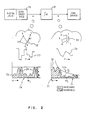
- a keyboard 1 inputs data to a processor 2 which translates this data into a stroke format, that is into a series of X, Y coordinates and beam brightness commands that when plotted, form a visual interpretation of the data. These coordinates are stored in memory 3 where they may be recalled repetitively for refreshing a CRT.
- the logic block 4 reads these coordinates in the proper sequence and converts them into X and Y signals 5 which are then filtered by dual filters 6.
- the filtered signals are then amplified by drivers 7 and input to yoke 8, causing a beam to deflect.
- This beam is modulated by a beam brightness control signal 9 to produce an image on CRT 10.
- This invention will focus on the filter 6, and a precompensation of endpoints, which may be effected in the logic block 4 or processor 2.
- the image is subject to a number of distortion factors, particularly in the deflection drivers 7 and yoke 8, which must be compensated.
- the present invention provides an expedient whereby the compensation or preliminary correction may be applied to the digital signal pattern before the signal pattern is converted into the analog voltage pattern.
- filter means are provided which substantially eliminate the effect on the deflected beam of any frequencies in the analog voltage pattern applied to the deflection means which are higher than one-half the stroke frequency of the CRT system. With this elimination, means for modifying the digital signal pattern for error precompensation are sufficient, rather than more costly expedients.
- the prior art system represented in Fig. 2, may be thought of as a zero-order hold 20 output through an integrator 21 to obtain straight-line interpolation.
- This model simplifies explanation of the spectrum of the signal to the yoke drivers.
- the output of the zero-order hold 20 would move the beam so as to form a series of dots on the screen 22.
- the beam velocity, forming the lines that are visually perceived, would be a series of impulses, and hence the visually perceived spectrum 24 at this point would contain a baseband 25 (slashed area) followed by equal intensity harmonic sidebands 26 on either side of any integer multiple of the sample frequency w s , extending to infinity.
- the perceived spectrum 24 is the spectrum of the derivative of the time- position function 23.
- the position derivatives or velocity, of the beam represents the visually preceived importance of each spectral component of the motion of the beam.
- the signal spectrum is essentially flat, and thus, using conventional terminology, "white”.
- the integrator block 21 provides an amplification proportional to 1/ ⁇ , where w is used conventionally to indicate frequency. This multiplies the spectrum of the signal from the zero-order hold 20, producing a "pink" spectrum 30.
- the analogues to the screen image 22 and proportional signal 23 are shown as 28 and 29.
- the multiplied spectrum 30 following the integrator 21 of Fig. 2 illustrates the signal that must be reproduced by the yoke and driver in vector stroke.
- the harmonics 31 are completely redundant to the baseband 32, they must be correctly followed.
- the worst problem is driver phase error, which usually appears at a lower frequency then driver amplitude distortion, and interacts with the vector harmonics to produce spiraling and linearity distortions of the "straight" lines.
- Adjustments of the endpoints cannot correct for the yoke and driver. Because of the spectral redundancy, correction of harmonics by adjusting endpoints distorts the baseband.
- the yoke and driver must have an undistorted passband substantially wider than the baseband of the digital signal.
- low-pass filter 50 is added to the positional signal path. Elements 20, 21, and 28 to 32 are identical to the same numbered elements in Fig. 2.
- the low pass filter 50 affects the positional signal plotted versus time in graph 29 to produce that of 51, modifying the screen image 28 of vector-stroke to image 52.
- the signal following the low-pass filter 50 has the form 53, which has none of the harmonics 31 of spectrum 30.
- any linear driver-yoke distortions can be exactly corrected by correcting the endpoints alone. Any errors in gain or phase are thus correctable by precorrecting endpoints, which may be done in software, or permanently in the character read only memory.
- the yoke can thus be driven as fast as the beam can be moved, without waiting for phase or gain to settle. Errors in the low-pass filter passband may be corrected as though part of the driver-yoke, removing many gain constraints and all phase constraints on the low-pass element. All that is required of the filter- drive-yoke function G(w), given sampling frequency ws, is that the ratio: be very small for all w ⁇ w s /2 and integer N ? 1.
- the full yoke- driver bandwidth can be utilized as illustrated in Fig. 4.
- This figure plots the frequency components of a signal in the prior art vector stroke 60 and those of a system using the teachings of this invention in plot 61.
- Three ranges of frequencies are shown: the maximum driveable range 63 includes those frequencies at and beyond yoke resonance at which current can be forced through a yoke to deflect a beam, but phase and amplitude distortions of the signal are severe.
- the controllable range 64 is shorter, and includes only those frequencies at which a system can be reasonably built to reproduce a signal with fidelity, and thus excludes the highest driveable frequencies.
- the third range 65 relates to the vector stroke spectrum 60. Because in vector stroke the harmonics 66 must be correctly reproduced as well as the baseband 67, the harmonics 66 must be within the controllable range 64, and hence the useful bandwidth 65, which is only the range covered by the baseband 67, must be quite short. On the other hand, because the method of this application permits simple correction of phase and amplitude distortions, and in addition there are no harmonics so the full bandwidth is useable, the spectrum 61 may extend to the maximum driveable frequency, and this it has a useful bandwidth 63 identical to the driveable range discussed above. A wider useful bandwidth means that strokes may be output faster, which means more strokes may be written into an image that must be completed and restarted for refresh in a fixed time limit, or a lower cost system may be used without reducing the number of strokes in an image.
- the stroke endpoint correction can be accomplished. If a character generator based system is used as in a text application, the predistortion may be computed once convolving the desired response with the inverse transfer function of the filler-driver-yoke combination, and the distorted symbols permanently stored.
- Another method of precorrection using modifiable memory to store an arbitrary string of stroke patterns uses a computer or equivalent hardware circuitryto digitally correct a string of stored digital numbers by convolution with the inverse transfer function of the display system.
- the string of stored digital numbers may be derived from a conventional character generator or other algorithm.
- the teachings of this invention permit complete correction by correcting only discrete numbers corresponding to stroke endpoints, and hence such a system is possible.
- the techniques of linear digital signal processing are well known in the art, and may be found in the text book, DIGITAL SIGNAL PROCESSING, by Oppenheim and Schafer, Prentice-Hall, 1975.
- a similar correction process may be accomplished in analog using an analog shift register and multipliers as in Fig. 6.
- the correction numbers which are the inverse of the filter-driver-yoke transform, are loaded into a series of registers 80. These numbers remain static, being changed only during trimming or alignment.
- the desired time discrete signal 81 is input to analog shift register 82.
- the output of each stage of the shift register is multiplied with the corresponding correction number by multipliers 83, and the product of all stages summed to form a convolution which is output 84.
- the registers 80 and multipliers 83 may be combined in a multiplying D/A converter, and of course other combinations are possible.
- the errors introduced by the filter-driver-yoke system will be non-minimum phase, and hence after precompensation a net group delay will occur.
- the beam switching signal must be delayed a matching amount so that the stroke will start and end at the desired points along the stroked line. This delay can be introduced by conventional means.
- the precompensation can be adjusted in phase so the required delay is an integer multiple of the stroke update frequency, allowing a simple shift register delay implementation.
- the filtered patterns of this application are non- redundant. They assume nothing, or, stated another way, they assume maximum entropy. They are adapted to non-specific patterns, such as most text, handwriting, graphics, and general non- coded information, A very readable font for text using only 4,5 strokes per character box is possible using the method taught in this application.
Landscapes
- Engineering & Computer Science (AREA)
- Radar, Positioning & Navigation (AREA)
- Remote Sensing (AREA)
- Physics & Mathematics (AREA)
- Computer Hardware Design (AREA)
- General Physics & Mathematics (AREA)
- Theoretical Computer Science (AREA)
- Controls And Circuits For Display Device (AREA)
- Control Of Indicators Other Than Cathode Ray Tubes (AREA)
Claims (6)
Applications Claiming Priority (2)
| Application Number | Priority Date | Filing Date | Title |
|---|---|---|---|
| US06/221,221 US4449124A (en) | 1980-12-30 | 1980-12-30 | Precompensated stroke cathode ray tube display system apparatus and method |
| US221221 | 1980-12-30 |
Publications (3)
| Publication Number | Publication Date |
|---|---|
| EP0055367A2 EP0055367A2 (de) | 1982-07-07 |
| EP0055367A3 EP0055367A3 (en) | 1984-08-22 |
| EP0055367B1 true EP0055367B1 (de) | 1988-01-27 |
Family
ID=22826894
Family Applications (1)
| Application Number | Title | Priority Date | Filing Date |
|---|---|---|---|
| EP81108975A Expired EP0055367B1 (de) | 1980-12-30 | 1981-10-27 | Vorkompensierte Kathodenstrahlanzeigeeinrichtung für Vektoren |
Country Status (4)
| Country | Link |
|---|---|
| US (1) | US4449124A (de) |
| EP (1) | EP0055367B1 (de) |
| JP (1) | JPS57125987A (de) |
| DE (1) | DE3176633D1 (de) |
Families Citing this family (3)
| Publication number | Priority date | Publication date | Assignee | Title |
|---|---|---|---|---|
| JPH01321767A (ja) * | 1988-06-24 | 1989-12-27 | Canon Inc | 画像読取走査装置 |
| JPH0332155A (ja) * | 1989-06-28 | 1991-02-12 | Canon Inc | 原稿読取装置 |
| US20050251353A1 (en) * | 2004-05-04 | 2005-11-10 | Zoltan Azary | System and method for analyzing an electrical network |
Family Cites Families (6)
| Publication number | Priority date | Publication date | Assignee | Title |
|---|---|---|---|---|
| US3364479A (en) * | 1963-07-31 | 1968-01-16 | Bunker Ramo | Line drawing system |
| US3333147A (en) * | 1963-07-31 | 1967-07-25 | Bunker Ramo | Line drawing system |
| US3437869A (en) * | 1965-11-01 | 1969-04-08 | Ibm | Display apparatus |
| GB1236950A (en) * | 1967-12-20 | 1971-06-23 | Iwatsu Electric Co Ltd | An improved graphic display |
| US3540032A (en) * | 1968-01-12 | 1970-11-10 | Ibm | Display system using cathode ray tube deflection yoke non-linearity to obtain curved strokes |
| US3786482A (en) * | 1972-03-13 | 1974-01-15 | Lexitron Corp | Apparatus for generating and displaying characters by tracing continuous strokes |
-
1980
- 1980-12-30 US US06/221,221 patent/US4449124A/en not_active Expired - Fee Related
-
1981
- 1981-10-27 DE DE8181108975T patent/DE3176633D1/de not_active Expired
- 1981-10-27 EP EP81108975A patent/EP0055367B1/de not_active Expired
- 1981-11-18 JP JP56183888A patent/JPS57125987A/ja active Granted
Also Published As
| Publication number | Publication date |
|---|---|
| DE3176633D1 (en) | 1988-03-03 |
| JPS6316748B2 (de) | 1988-04-11 |
| JPS57125987A (en) | 1982-08-05 |
| US4449124A (en) | 1984-05-15 |
| EP0055367A2 (de) | 1982-07-07 |
| EP0055367A3 (en) | 1984-08-22 |
Similar Documents
| Publication | Publication Date | Title |
|---|---|---|
| KR100571219B1 (ko) | 3차원 가상 스크린 기반 영상왜곡 보정장치 | |
| JPH05244615A (ja) | ディジタルコンバーゼンス補正装置及び補正データの作成方法 | |
| CN102054424B (zh) | 图像处理装置及图像处理方法 | |
| US6124685A (en) | Method for correcting distortion of image displayed on display device, distortion detecting unit, distortion correcting unit and display device having such distortion correcting unit | |
| US4795946A (en) | Method of and circuit for correcting linearity of horizontal deflection system | |
| EP0055367B1 (de) | Vorkompensierte Kathodenstrahlanzeigeeinrichtung für Vektoren | |
| JPH06217236A (ja) | 表示装置 | |
| US5448140A (en) | Image display apparatus with a deflection circuit having function for correcting rotational distortion | |
| US4623825A (en) | Delay compensation in electromagnetic deflection systems | |
| EP0125372B1 (de) | Vorrichtung zum Darstellen von Wellenformen | |
| US7166972B2 (en) | Vertical deflection apparatus | |
| JPH0259792A (ja) | 水平s字歪み補正回路 | |
| JP2002199248A (ja) | 画像エンハンス方法及び装置 | |
| JPS59105782A (ja) | 画像ひずみ補正装置 | |
| JPS6261187B2 (de) | ||
| JP2907868B2 (ja) | 水平偏向歪自動補正式デイスプレイ | |
| CN1659857B (zh) | 图形显示装置 | |
| EP0598442B1 (de) | Wiedergabeanordnung mit einer Korrekturschaltung und Korrekturschaltung zum Gebrauch in einer solchen Anordnung | |
| US5047756A (en) | Video compensation apparatus for stroke mode CRT displays | |
| JPH04316094A (ja) | 記号再生方法 | |
| KR100339380B1 (ko) | 영상기기의 화면조정신호 생성장치 및 방법 | |
| JPS60160268A (ja) | カラ−ビデオ画質調整装置 | |
| KR930000855Y1 (ko) | 수평선형성 조정회로 | |
| JPS6086966A (ja) | ブラウン管表示装置 | |
| JPH05145781A (ja) | Crt画像のローテーシヨン歪補正方法、crtの偏向回路及び画像表示装置 |
Legal Events
| Date | Code | Title | Description |
|---|---|---|---|
| PUAI | Public reference made under article 153(3) epc to a published international application that has entered the european phase |
Free format text: ORIGINAL CODE: 0009012 |
|
| 17P | Request for examination filed |
Effective date: 19811027 |
|
| AK | Designated contracting states |
Designated state(s): DE FR GB |
|
| PUAL | Search report despatched |
Free format text: ORIGINAL CODE: 0009013 |
|
| AK | Designated contracting states |
Designated state(s): DE FR GB |
|
| GRAA | (expected) grant |
Free format text: ORIGINAL CODE: 0009210 |
|
| AK | Designated contracting states |
Kind code of ref document: B1 Designated state(s): DE FR GB |
|
| REF | Corresponds to: |
Ref document number: 3176633 Country of ref document: DE Date of ref document: 19880303 |
|
| ET | Fr: translation filed | ||
| PLBE | No opposition filed within time limit |
Free format text: ORIGINAL CODE: 0009261 |
|
| STAA | Information on the status of an ep patent application or granted ep patent |
Free format text: STATUS: NO OPPOSITION FILED WITHIN TIME LIMIT |
|
| 26N | No opposition filed | ||
| PGFP | Annual fee paid to national office [announced via postgrant information from national office to epo] |
Ref country code: GB Payment date: 19900911 Year of fee payment: 10 |
|
| PGFP | Annual fee paid to national office [announced via postgrant information from national office to epo] |
Ref country code: FR Payment date: 19900926 Year of fee payment: 10 |
|
| PGFP | Annual fee paid to national office [announced via postgrant information from national office to epo] |
Ref country code: DE Payment date: 19901027 Year of fee payment: 10 |
|
| PG25 | Lapsed in a contracting state [announced via postgrant information from national office to epo] |
Ref country code: GB Effective date: 19911027 |
|
| GBPC | Gb: european patent ceased through non-payment of renewal fee | ||
| PG25 | Lapsed in a contracting state [announced via postgrant information from national office to epo] |
Ref country code: FR Effective date: 19920630 |
|
| PG25 | Lapsed in a contracting state [announced via postgrant information from national office to epo] |
Ref country code: DE Effective date: 19920701 |
|
| REG | Reference to a national code |
Ref country code: FR Ref legal event code: ST |