EP0055008B1 - Interrupteur à vide - Google Patents
Interrupteur à vide Download PDFInfo
- Publication number
- EP0055008B1 EP0055008B1 EP81301116A EP81301116A EP0055008B1 EP 0055008 B1 EP0055008 B1 EP 0055008B1 EP 81301116 A EP81301116 A EP 81301116A EP 81301116 A EP81301116 A EP 81301116A EP 0055008 B1 EP0055008 B1 EP 0055008B1
- Authority
- EP
- European Patent Office
- Prior art keywords
- electrode
- vacuum interrupter
- slots
- electrodes
- current
- Prior art date
- Legal status (The legal status is an assumption and is not a legal conclusion. Google has not performed a legal analysis and makes no representation as to the accuracy of the status listed.)
- Expired
Links
- 230000003014 reinforcing effect Effects 0.000 claims description 9
- 239000002184 metal Substances 0.000 claims description 4
- 229910052751 metal Inorganic materials 0.000 claims description 4
- 238000013459 approach Methods 0.000 claims description 3
- 239000012779 reinforcing material Substances 0.000 claims 1
- 239000004020 conductor Substances 0.000 description 16
- 230000000694 effects Effects 0.000 description 12
- 230000002411 adverse Effects 0.000 description 4
- 238000009827 uniform distribution Methods 0.000 description 3
- 230000004907 flux Effects 0.000 description 2
- 229910001220 stainless steel Inorganic materials 0.000 description 2
- 239000010935 stainless steel Substances 0.000 description 2
- RYGMFSIKBFXOCR-UHFFFAOYSA-N Copper Chemical compound [Cu] RYGMFSIKBFXOCR-UHFFFAOYSA-N 0.000 description 1
- 230000000712 assembly Effects 0.000 description 1
- 238000000429 assembly Methods 0.000 description 1
- 229910052802 copper Inorganic materials 0.000 description 1
- 239000010949 copper Substances 0.000 description 1
- 239000011810 insulating material Substances 0.000 description 1
- 239000000696 magnetic material Substances 0.000 description 1
- 238000004519 manufacturing process Methods 0.000 description 1
- 230000002093 peripheral effect Effects 0.000 description 1
- 230000002265 prevention Effects 0.000 description 1
- 230000035939 shock Effects 0.000 description 1
- 230000002195 synergetic effect Effects 0.000 description 1
Images


Classifications
-
- H—ELECTRICITY
- H01—ELECTRIC ELEMENTS
- H01H—ELECTRIC SWITCHES; RELAYS; SELECTORS; EMERGENCY PROTECTIVE DEVICES
- H01H33/00—High-tension or heavy-current switches with arc-extinguishing or arc-preventing means
- H01H33/60—Switches wherein the means for extinguishing or preventing the arc do not include separate means for obtaining or increasing flow of arc-extinguishing fluid
- H01H33/66—Vacuum switches
- H01H33/664—Contacts; Arc-extinguishing means, e.g. arcing rings
- H01H33/6644—Contacts; Arc-extinguishing means, e.g. arcing rings having coil-like electrical connections between contact rod and the proper contact
-
- H—ELECTRICITY
- H01—ELECTRIC ELEMENTS
- H01H—ELECTRIC SWITCHES; RELAYS; SELECTORS; EMERGENCY PROTECTIVE DEVICES
- H01H33/00—High-tension or heavy-current switches with arc-extinguishing or arc-preventing means
- H01H33/60—Switches wherein the means for extinguishing or preventing the arc do not include separate means for obtaining or increasing flow of arc-extinguishing fluid
- H01H33/66—Vacuum switches
- H01H33/664—Contacts; Arc-extinguishing means, e.g. arcing rings
- H01H33/6643—Contacts; Arc-extinguishing means, e.g. arcing rings having disc-shaped contacts subdivided in petal-like segments, e.g. by helical grooves
Definitions
- the present invention relates to a vacuum interrupter which avoids the adverse effects of eddy currents.
- interruption properties of a vacuum interrupter may be improved by applying a magnetic field oriented in parallel with an arc produced when the contact members of the vacuum interrupter separate.
- Figure 1 shows the electrode structure of the conventional vacuum interrupter, Figure 1(a) being a side view and Figure 1(b) being a plan view of the structure.
- Figures 1 (a), (b) are schematic views of a conventional vacuum interrupter showing the structure of one contact member of the interrupter.
- the reference numeral (1) designates a conductive rod; and the reference numeral (20) designates a coil electrode, which comprises an arm projecting radially from a base of the conductive rod (1), a single-turn coil and a connection (21) to a main electrode (3).
- the coil electrode (20) is shown in the form of a single-turn coil but plural such coil electrodes (20) can be connected together at the back of the main electrode (3).
- the reference (A) designates an arc formed between the main electrode and a counter electrode of an opposed contact member (not shown); and the reference (i) designates a current flowing when the arc is produced, the direction of the current being shown by the line of arrows.
- the electrode assembly does not perform satisfactorily.
- the intensity of the magnetic field is reduced as a result of the distance of the coil electrode from the surface of the main electrode where the arc is generated, because the coil electrode is formed in the back side of the main electrode.
- vacuum interrupters are known from US-A-4196327 and GB-A-2038557 having contact members with a similar structure to that described above, except in that the coil electrode is replaced by an annular electrode connected to the conductive rod by two or more radial arms. Consequently similar problems can at least to some extent be expected with these structures.
- a vacuum interrupter including a fixed contact member and a movable contact member, each comprising a conductive rod and an electrode, the conductive rod and the electrode being electrically connected by means of a connecting part and mechanically connected by means of a reinforcing member, characterised in that each of the electrodes has a slot therein, one end of which intersects part of the periphery of the electrode and the other end of which approaches another part of the periphery of the electrode whereby to a current path in the electrode, and in that each connecting part connects the conductive rod to the electrode near the slot whereby during the opening of the contact members a magnetic field oriented in parallel with the arc struck between said electrodes is formed.
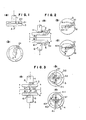
- Figure 2(a) is a side view of a pair of contact members
- Figure 2(b) is a plan view in the direction of arrows a-b (hereinafter referred to as the (a-b) arrow view)
- Figure 2(c) is a plan view in the direction of arrows e-d (hereinafter referred to as the (c-d) arrow view).
- the reference numerals (1) and (6) respectively designate conductive rods, each of which is mechanically connected through a reinforcing part (11) or (61) made of a metal of high resistance, such as stainless steel, to an electrode (3) or (4).
- a current conductor (2) or (5) provides an electrical connection from the base of each conductive rod (1) or (6) through a respective connecting part (21) or (51) to each electrode (3) or (4) as described below.
- a slot (31) or (41) is formed in each electrode (3) or (4) to pass through the full thickness of the electrode and to intersect the periphery of one portion of the electrode and extend across its centre so that the end (311) or (411) of the slot approaches near the periphery of an opposed portion of the electrode.
- one of the pair of the electrode assemblies in a vacuum interrupter forms a stationary contact member and the other forms a movable contact member.
- the upper electrode assembly shown by the (a-b) arrow view is the stationary contact member and the lower electrode assembly shown by the (e-d) arrow view is the movable contact member.
- the pair of electrodes (3), (4) are oriented so that the slots (31, (41) face in the same direction.
- the conductor (2) or (5) is electrically connected by the connecting part (21) or (51) to the back surface of the electrode near the portion of the periphery intersected by the slot (31) or (41).
- the relative positions of the conductors (2), (5) are such that they face one another across the slots (31), (41) so as to avoid superposition of the connecting parts (21), (51).
- the current i passes, as shown by the lines of arrows in Figures 2(a), (b), (c), from the conductive rod (1) of the stationary contact member through the current conductor (2) and the connecting part (21) to the electrode (3).
- the current passes through the connecting part (21) to the arc point A.
- the current further passes through the arc plasma to the arc point B of the counter electrode (4).
- the current passes from the arc point B through the part of the electrode (4) between the end (411) of the groove (41) and the adjacent periphery of the electrode and through the connecting part (51) and the current conductor (5) to the conductive rod (6).
- the passage of the current i passing through the electrodes (3), (4) as (21) ⁇ A and B-->(51) is in a loop conforming to a single turn of a coil whereby a magnetic flux is generated in parallel with the arc A-B.
- the intensity of the magnetic field is remarkably high because it is formed by the current passing through the electrodes near the arc.
- eddy currents are effectively reduced by the slots (31), (41). Therefore, a stable arc having uniform distribution is provided which is superior to the arc obtained by the conventional device.
- the adverse effect on the magnetic field caused by eddy currents in the conductive rod (6) to the electrode (3) can be eliminated by selecting a large thickness for the reinforcing part (61). Therefore, lagging of the vertical magnetic field at zero current is reduced to effectively prevent erroneous re-arching.
- the coil electrode required in the conventional device is eliminated whereby a remarkably simple structure having a high mechanical strength, without any trouble from eddy currents, can be obtained.
- the current passing through the inner parts of the electrodes in the closed state of the interrupter is in the same direction for both electrodes whereby the electrodes are attracted to each other by the electromagnetic attractive force resulting from the current passing in parallel and the contact pressure between the electrodes is increased. Therefore, the contacting force which is externally applied can be reduced substantially by comparison with the conventional device.
- branch slots (52) extending radially from and equally spaced about the centre of the electrode as shown in Figure 5(a).
- the current path is shifted from the path in the embodiment of Figure 2 towards the periphery of the electrode. Therefore, a current path corresponding to that in a coil can be further approximated.
- the current conductor (2) or (5) is in the form of an arm connected to the conductive rod (1) or (6).
- the electrode in a conical shape having a flat circular top (30) or (40) with slots whose ends (311), (411) are at the inclined conical surface whereby the arcing point can be selected to be outside the narrow gaps between the slot ends and the periphery of the electrode.
- the slots of the pair of electrodes are superposed to place the connecting parts (21), (51) of the current conductors (2), (5) on opposite sides of the aligned slots.
- the slot(s) formed in each electrode cause the current occurring during arcing to pass around the end(s) of the slot(s) thereby forming a current loop and producing a magnetic field near the arc which is oriented in parallel with the arc. Therefore, the mechanical and electrical characteristics of the vacuum interrupter may be improved significantly.
- Figure 6(a) is a side view of a pair of contact members and Figure 6(b) is an (a-b) arrow view and Figure 6(c) is a (c-d) arrow view.
- the reference numerals (1) and (6) respectively designate conductive rods, each of which is mechanically connected to an electrode (3) or (4) through a reinforcing part (11) or (61) made of a metal of high resistance such as stainless steel.
- Each current conductor (2) or (6) through the connecting part (21) or (51) to the electrode (3) or (4).
- the current conductors (2) or (5) are symmetrically positioned relative to the axis of the electrodes.
- Slots (31), (32), (33), (34), (41), (42), (43), (44) are formed in parallel in the electrodes (3), (4) through the full thickness thereof with their one ends intersecting the periphery of each electrode at one side and their other ends (311), (321), (331), (341), (411), (421), (431), (441) approaching the periphery at the other side of each electrode.
- the slots in the electrodes (3), (4) are arranged to extend in the opposite directions. As shown in the (a-b) arrow view of Figure 6(b) and the (c-d) arrow view of Figure 6(c), both electrodes (3), (4) have the same structure but they are rotated through 180 degrees about the axis of the electrodes to provide this arrangement of the slots.
- the current i passes as shown by the arrowed lines in Figures 6(a), (b), (c) from the conductive rod (1) through the current conductor (2) and the connecting part (21) to the electrode (3), and is guided along through the path defined between the slots (31), (32) to the peripheral region of the electrode (3) at the opposite side from the connecting part (21).
- the current i is divided into the current i 2 passing to the arc point A and the current i 2 passing to the arc point C.
- the current i passes along the path defined by the slots (31), (33) to the arc point A and passes across the arc plasma to the arc point B of the other electrode (4).
- the current i passes from the arc point B along the path defined by the slots (41), (43) to the end (411) of the slot (41).
- the current i is combined with the current i 2 , which passed around the periphery of the electrode (3) to the arc point C, across to the arc point D of the other electrode and around the periphery of the electrode (4).
- the combined current passes along the path defined by the slots (41), (42) to the connecting part (51) and further passes through the current conductor (5) to the electrode (6).
- the intensity of the magnetic field is remarkably high because it is generated by current passing through the electrodes near the arc. This provides a stable arc having a uniform distribution. Eddy currents are effectively reduced by the slots whereby it is unnecessary to take special precautions for reducing eddy currents as required in the conventional device.
- the currents in the pair of electrodes are in the same direction in both the path defined by the slots (31), (32) and the path defined by the slots (41), (42) whereby the electrodes are mutually attracted by the electromagnetic force resulting from the current passing in parallel through the electrodes, which enhances the contact pressure of the electrodes. Therefore, the contacting force which is externally applied can be reduced substantially on comparison with the conventional device.
- the slots in each electrode all extend in the same direction.
- the current conductors (2), (5) and the slots (31), (41) etc. are arranged to extend in the same direction.
- the current conductors (2), (5) are superposed.
- the slots are curved with a desired curvature.
- the slots are rectangular.
- the other parts of these structures are the same as in the embodiment of Figure 9.
- the magnetic field is oriented in parallel with the arc generated between the electrodes to achieve the effect described above.
- the slots formed in the electrodes serve to pass the arc current along the paths defined by the slots to provide a magnetic field near the arc which is oriented in parallel with the arc whereby the mechanical and electrical characteristics of the interrupter can be improved markedly.
- the slots may be filled with an insulating material if desired.
Landscapes
- High-Tension Arc-Extinguishing Switches Without Spraying Means (AREA)
Claims (9)
Applications Claiming Priority (4)
| Application Number | Priority Date | Filing Date | Title |
|---|---|---|---|
| JP182216/80 | 1980-12-22 | ||
| JP18221680A JPS57105930A (en) | 1980-12-22 | 1980-12-22 | Vacuum breaker |
| JP18311780A JPS57105931A (en) | 1980-12-23 | 1980-12-23 | Vacuum breaker |
| JP183117/80 | 1980-12-23 |
Publications (3)
| Publication Number | Publication Date |
|---|---|
| EP0055008A2 EP0055008A2 (fr) | 1982-06-30 |
| EP0055008A3 EP0055008A3 (en) | 1983-03-16 |
| EP0055008B1 true EP0055008B1 (fr) | 1985-12-11 |
Family
ID=26501097
Family Applications (1)
| Application Number | Title | Priority Date | Filing Date |
|---|---|---|---|
| EP81301116A Expired EP0055008B1 (fr) | 1980-12-22 | 1981-03-17 | Interrupteur à vide |
Country Status (3)
| Country | Link |
|---|---|
| US (1) | US4415787A (fr) |
| EP (1) | EP0055008B1 (fr) |
| DE (1) | DE3173171D1 (fr) |
Families Citing this family (13)
| Publication number | Priority date | Publication date | Assignee | Title |
|---|---|---|---|---|
| DE8437054U1 (de) * | 1984-12-18 | 1986-06-26 | Siemens AG, 1000 Berlin und 8000 München | Schaltkontakt für eine Vakuumschaltröhre |
| JPS61195528A (ja) * | 1985-02-22 | 1986-08-29 | 三菱電機株式会社 | 真空しや断器の電極構造 |
| EP0245513B1 (fr) * | 1985-11-12 | 1993-09-29 | Mitsubishi Denki Kabushiki Kaisha | Interrupteur sous vide |
| DE3610241A1 (de) * | 1986-03-26 | 1987-10-01 | Siemens Ag | Kontaktanordnung fuer vakuumschalter mit axialem magnetfeld |
| WO1987006052A1 (fr) * | 1986-03-26 | 1987-10-08 | Siemens Aktiengesellschaft Berlin Und München | Systeme de contacts pour interrupteur a vide avec champ magnetique axial |
| DE3644453A1 (de) * | 1986-12-24 | 1988-07-07 | Licentia Gmbh | Schaltstueck fuer leistungsschalter |
| FR2726396B1 (fr) * | 1994-10-31 | 1996-12-13 | Schneider Electric Sa | Interrupteur electrique sous vide |
| JP3462367B2 (ja) * | 1997-06-27 | 2003-11-05 | 株式会社日立製作所 | 複合絶縁開閉装置 |
| KR100295905B1 (ko) * | 1998-07-18 | 2001-08-07 | 이종수 | 진공인터럽터용전극구조체 |
| CN106128851B (zh) * | 2016-06-30 | 2018-07-06 | 西安交通大学 | 一种两极式复合纵磁铁心式触头结构及真空灭弧室 |
| CN107086149A (zh) * | 2017-06-05 | 2017-08-22 | 西安交通大学 | 一种高压真空灭弧室马蹄铁型纵磁触头导电结构 |
| CN107093535B (zh) * | 2017-06-06 | 2020-02-11 | 西安交通大学 | 一种高额定电流纵向磁场真空灭弧室触头结构 |
| DE102019216873A1 (de) * | 2019-10-31 | 2021-05-06 | Siemens Aktiengesellschaft | Kontaktelement zum Kontaktieren mit einem weiteren Kontaktelement für einen Leistungsschalter, insbesondere eine Vakuum-Schaltröhre, ein Leistungsschalter, insbesondere eine Vakuum-Schaltröhre, und ein Verfahren zum Herstellen eines Kontaktelements |
Family Cites Families (6)
| Publication number | Priority date | Publication date | Assignee | Title |
|---|---|---|---|---|
| US2949520A (en) * | 1958-04-23 | 1960-08-16 | Gen Electric | Contact structure for an electric circuit interrupter |
| GB1425641A (en) * | 1972-07-19 | 1976-02-18 | Siemens Ag | Vacuum switches |
| SE392781B (sv) * | 1973-09-10 | 1977-04-18 | Tokyo Shibaura Electric Co | Vakuumbrytare |
| DE2429484A1 (de) * | 1974-06-20 | 1976-01-08 | Siemens Ag | Kontaktanordnung fuer vakuumschalter |
| JPS58810B2 (ja) * | 1976-12-06 | 1983-01-08 | 株式会社日立製作所 | 真空しや断器 |
| JPS5826132B2 (ja) * | 1978-11-22 | 1983-06-01 | 株式会社日立製作所 | 真空しや断器 |
-
1981
- 1981-03-17 DE DE8181301116T patent/DE3173171D1/de not_active Expired
- 1981-03-17 EP EP81301116A patent/EP0055008B1/fr not_active Expired
- 1981-03-23 US US06/246,639 patent/US4415787A/en not_active Expired - Fee Related
Also Published As
| Publication number | Publication date |
|---|---|
| EP0055008A3 (en) | 1983-03-16 |
| DE3173171D1 (en) | 1986-01-23 |
| US4415787A (en) | 1983-11-15 |
| EP0055008A2 (fr) | 1982-06-30 |
Similar Documents
| Publication | Publication Date | Title |
|---|---|---|
| EP0055008B1 (fr) | Interrupteur à vide | |
| US6506992B2 (en) | Vacuum interrupter for vacuum breaker | |
| CN101834086B (zh) | 用于真空断续器的电极 | |
| US6163002A (en) | Vacuum circuit interrupter with contact structure including support pins | |
| EP0208271B1 (fr) | Interrupteur à vide | |
| EP0329410B1 (fr) | Interrupteur à vide | |
| CA1117572A (fr) | Commutateur a vide pouvant creer un champ magnetique axial entre des faces de contact | |
| US20060124600A1 (en) | Vacuum interrupter | |
| US6479778B1 (en) | Vacuum switch including windmill-shaped electrodes | |
| US5691522A (en) | Vacuum interrupter with a single internal assembly for generating an axial magnetic field | |
| EP0133368A2 (fr) | Contact pour interrupteur haut courant | |
| US5726406A (en) | Electrical vacuum switch | |
| KR101003685B1 (ko) | 진공 인터럽터의 전극 | |
| JPS58157017A (ja) | しや断器用真空バルブ | |
| KR101601619B1 (ko) | 진공 밸브 | |
| US4855547A (en) | Vacuum interrupter | |
| GB2188487A (en) | Arcing electrode for switch | |
| US4392035A (en) | Vacuum interrupter | |
| JPS6329366B2 (fr) | ||
| CA1066334A (fr) | Disjoncteur a vide a deux ensembles de contacts electriquement en parallele | |
| US3699290A (en) | Electric circuit breakers | |
| JPS6161491B2 (fr) | ||
| JPS62113328A (ja) | 真空しや断器 | |
| JPS6336916Y2 (fr) | ||
| JPS5911168B2 (ja) | 真空しや断器 |
Legal Events
| Date | Code | Title | Description |
|---|---|---|---|
| PUAI | Public reference made under article 153(3) epc to a published international application that has entered the european phase |
Free format text: ORIGINAL CODE: 0009012 |
|
| 17P | Request for examination filed |
Effective date: 19811029 |
|
| AK | Designated contracting states |
Designated state(s): DE FR GB NL SE |
|
| PUAL | Search report despatched |
Free format text: ORIGINAL CODE: 0009013 |
|
| AK | Designated contracting states |
Designated state(s): DE FR GB NL SE |
|
| GRAA | (expected) grant |
Free format text: ORIGINAL CODE: 0009210 |
|
| AK | Designated contracting states |
Designated state(s): DE FR GB NL SE |
|
| REF | Corresponds to: |
Ref document number: 3173171 Country of ref document: DE Date of ref document: 19860123 |
|
| ET | Fr: translation filed | ||
| PLBE | No opposition filed within time limit |
Free format text: ORIGINAL CODE: 0009261 |
|
| STAA | Information on the status of an ep patent application or granted ep patent |
Free format text: STATUS: NO OPPOSITION FILED WITHIN TIME LIMIT |
|
| 26N | No opposition filed | ||
| PGFP | Annual fee paid to national office [announced via postgrant information from national office to epo] |
Ref country code: SE Payment date: 19930315 Year of fee payment: 13 |
|
| PG25 | Lapsed in a contracting state [announced via postgrant information from national office to epo] |
Ref country code: SE Free format text: LAPSE BECAUSE OF NON-PAYMENT OF DUE FEES Effective date: 19940318 |
|
| EUG | Se: european patent has lapsed |
Ref document number: 81301116.0 Effective date: 19941010 |
|
| PGFP | Annual fee paid to national office [announced via postgrant information from national office to epo] |
Ref country code: GB Payment date: 19950307 Year of fee payment: 15 |
|
| PGFP | Annual fee paid to national office [announced via postgrant information from national office to epo] |
Ref country code: FR Payment date: 19950309 Year of fee payment: 15 Ref country code: DE Payment date: 19950309 Year of fee payment: 15 |
|
| PG25 | Lapsed in a contracting state [announced via postgrant information from national office to epo] |
Ref country code: GB Effective date: 19960317 |
|
| GBPC | Gb: european patent ceased through non-payment of renewal fee |
Effective date: 19960317 |
|
| PG25 | Lapsed in a contracting state [announced via postgrant information from national office to epo] |
Ref country code: FR Effective date: 19961129 |
|
| PG25 | Lapsed in a contracting state [announced via postgrant information from national office to epo] |
Ref country code: DE Effective date: 19961203 |
|
| REG | Reference to a national code |
Ref country code: FR Ref legal event code: ST |
|
| PGFP | Annual fee paid to national office [announced via postgrant information from national office to epo] |
Ref country code: NL Payment date: 19980326 Year of fee payment: 18 |
|
| PG25 | Lapsed in a contracting state [announced via postgrant information from national office to epo] |
Ref country code: NL Free format text: LAPSE BECAUSE OF NON-PAYMENT OF DUE FEES Effective date: 19991001 |
|
| NLV4 | Nl: lapsed or anulled due to non-payment of the annual fee |
Effective date: 19991001 |