EP0054955A2 - Cryogenic freezing system - Google Patents
Cryogenic freezing system Download PDFInfo
- Publication number
- EP0054955A2 EP0054955A2 EP81110663A EP81110663A EP0054955A2 EP 0054955 A2 EP0054955 A2 EP 0054955A2 EP 81110663 A EP81110663 A EP 81110663A EP 81110663 A EP81110663 A EP 81110663A EP 0054955 A2 EP0054955 A2 EP 0054955A2
- Authority
- EP
- European Patent Office
- Prior art keywords
- freezer
- air
- main
- bag
- articles
- Prior art date
- Legal status (The legal status is an assumption and is not a legal conclusion. Google has not performed a legal analysis and makes no representation as to the accuracy of the status listed.)
- Withdrawn
Links
Images

Classifications
-
- B—PERFORMING OPERATIONS; TRANSPORTING
- B01—PHYSICAL OR CHEMICAL PROCESSES OR APPARATUS IN GENERAL
- B01D—SEPARATION
- B01D46/00—Filters or filtering processes specially modified for separating dispersed particles from gases or vapours
- B01D46/02—Particle separators, e.g. dust precipitators, having hollow filters made of flexible material
- B01D46/04—Cleaning filters
-
- A—HUMAN NECESSITIES
- A23—FOODS OR FOODSTUFFS; TREATMENT THEREOF, NOT COVERED BY OTHER CLASSES
- A23L—FOODS, FOODSTUFFS, OR NON-ALCOHOLIC BEVERAGES, NOT COVERED BY SUBCLASSES A21D OR A23B-A23J; THEIR PREPARATION OR TREATMENT, e.g. COOKING, MODIFICATION OF NUTRITIVE QUALITIES, PHYSICAL TREATMENT; PRESERVATION OF FOODS OR FOODSTUFFS, IN GENERAL
- A23L3/00—Preservation of foods or foodstuffs, in general, e.g. pasteurising, sterilising, specially adapted for foods or foodstuffs
- A23L3/36—Freezing; Subsequent thawing; Cooling
- A23L3/37—Freezing; Subsequent thawing; Cooling with addition of or treatment with chemicals
- A23L3/375—Freezing; Subsequent thawing; Cooling with addition of or treatment with chemicals with direct contact between the food and the chemical, e.g. liquid nitrogen, at cryogenic temperature
-
- B—PERFORMING OPERATIONS; TRANSPORTING
- B01—PHYSICAL OR CHEMICAL PROCESSES OR APPARATUS IN GENERAL
- B01D—SEPARATION
- B01D46/00—Filters or filtering processes specially modified for separating dispersed particles from gases or vapours
- B01D46/42—Auxiliary equipment or operation thereof
- B01D46/4281—Venturi's or systems showing a venturi effect
-
- B—PERFORMING OPERATIONS; TRANSPORTING
- B01—PHYSICAL OR CHEMICAL PROCESSES OR APPARATUS IN GENERAL
- B01D—SEPARATION
- B01D46/00—Filters or filtering processes specially modified for separating dispersed particles from gases or vapours
- B01D46/66—Regeneration of the filtering material or filter elements inside the filter
- B01D46/70—Regeneration of the filtering material or filter elements inside the filter by acting counter-currently on the filtering surface, e.g. by flushing on the non-cake side of the filter
- B01D46/71—Regeneration of the filtering material or filter elements inside the filter by acting counter-currently on the filtering surface, e.g. by flushing on the non-cake side of the filter with pressurised gas, e.g. pulsed air
-
- F—MECHANICAL ENGINEERING; LIGHTING; HEATING; WEAPONS; BLASTING
- F25—REFRIGERATION OR COOLING; COMBINED HEATING AND REFRIGERATION SYSTEMS; HEAT PUMP SYSTEMS; MANUFACTURE OR STORAGE OF ICE; LIQUEFACTION SOLIDIFICATION OF GASES
- F25B—REFRIGERATION MACHINES, PLANTS OR SYSTEMS; COMBINED HEATING AND REFRIGERATION SYSTEMS; HEAT PUMP SYSTEMS
- F25B9/00—Compression machines, plants or systems, in which the refrigerant is air or other gas of low boiling point
- F25B9/002—Compression machines, plants or systems, in which the refrigerant is air or other gas of low boiling point characterised by the refrigerant
- F25B9/004—Compression machines, plants or systems, in which the refrigerant is air or other gas of low boiling point characterised by the refrigerant the refrigerant being air
-
- F—MECHANICAL ENGINEERING; LIGHTING; HEATING; WEAPONS; BLASTING
- F25—REFRIGERATION OR COOLING; COMBINED HEATING AND REFRIGERATION SYSTEMS; HEAT PUMP SYSTEMS; MANUFACTURE OR STORAGE OF ICE; LIQUEFACTION SOLIDIFICATION OF GASES
- F25D—REFRIGERATORS; COLD ROOMS; ICE-BOXES; COOLING OR FREEZING APPARATUS NOT OTHERWISE PROVIDED FOR
- F25D21/00—Defrosting; Preventing frosting; Removing condensed or defrost water
- F25D21/06—Removing frost
-
- B—PERFORMING OPERATIONS; TRANSPORTING
- B01—PHYSICAL OR CHEMICAL PROCESSES OR APPARATUS IN GENERAL
- B01D—SEPARATION
- B01D2201/00—Details relating to filtering apparatus
- B01D2201/31—Other construction details
- B01D2201/313—Means for protecting the filter from the incoming fluid, e.g. shields
Definitions
- the present invention relates to systems for freezing articles in a freezer using a circulation system of air at cryogenic temperatures. It is particularly concerned with a more efficient circulating air refrigeration system for large scale food freezing applications.
- Refrigeration systems employing air at cryogenic temperatures for freezing food are commercially available, for example, see U.S. Patent Nos. 3,733,848 and 3,868,827.
- air is compressed in a first stage compressor, cooled in an intercooler, further compressed in a second stage compressor, cooled in another intercooler, further cooled by countercurrent exchange with cold air leaving the freezer and finally expanded in an expansion turbine mechanically coupled to the second stage compressor where the gas is reduced to about -180°F before being directed into the freezer.
- This prior art freezer has been used in combination with a vortex separator for removing particles of ice in excess of 5 microns in diameter from the air leaving the food freezer.
- this separation ice has been found to build up in the regenerative heat exchanger and to result in an intolerable pressure drop across the main heat exchanger which greatly reduces the efficiency of this system.
- the present novel system affords greater efficiency by replacing the vortex separator with a pulse bag filter to maintain the temperature of the air leaving the freezer at temperatures of below -80°F. Additional efficiency is achieved by supplying dry air to maintain an air curtain at the inlet and outlet of the freezer to prevent entry of warm, moist atmospheric air into the freezer and subsequent refrigeration loss. Finally, air is introduced into the bottom of the freezer adjacent to the freezer inlet to promote more rapid freezing of the food articles, thus limiting the dehydration of the food products and the ice formed therefrom.
- the novel system which is used for refrigeration, particularly in the rapid freezing of food products comprises a freezer having an inlet for admitting the articles to be frozen, an outlet for permitting the frozen articles to leave said freezer and a conveyor for transporting the articles through the freezer from the inlet to the outlet thereof; a refrigerant supply main connected to the freezer for introducing refrigerant air to the freezer; a return main connected to the freezer for-receiving the warmed air from the freezer; refrigeration means connected to the refrigerant supply main for supplying the supply main with air at cryogenic temperatures; a main heat exchanger having a high pressure side connected to the refrigeration means and a low pressure side connected between the refrigeration means and the return-main for exchanging the refrigerant value of the warmed air from the return main in the low pressure side with the air from the refrigeration means in the high pressure side; and bag filter means connected between the return main and the main exchanger for removing ice particles from the warmed air in said return main prior to exchanging
- the filter means comprises at least one bag which is periodically pulsed to remove ice collected on the outside thereof through the pulsing action of a portion of the air leaving the high pressure side of the main heat exchanger prior to entering an expansion portion of the refrigeration means.
- the refrigeration means comprises three stages of compression and one expansion turbine.
- the air in the system is progressively compressed by the three compressor stages, is cooled in the main heat exchanger and is expanded in the expander of the refrigeration means before being introduced into the freezer.
- the air that is withdrawn from the freezer is passed through the bags of the pulse bag filter to remove ice particles in excess of approximately 1 micron in diameter, is warmed in the main heat exchanger and is recycled through the refrigeration means.
- the present apparatus and method thereof enable one to recover air from the exit of the freezer at temperatures colder than -80°F.
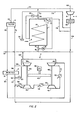
- FIG. 1 illustrates the combination of freezer 1, refrigeration unit 2, main heat exchanger 3, make-up air system 4 and filter 5 comprising bag 6 and rotary valve 7.
- filter 5 comprising bag 6 and rotary valve 7.
- freezer 1 is shown having feed-station 8, discharge station 9 and continuous belt conveyor 10 for transporting the articles to be frozen through the freezer.
- feed-station 8 discharge station 9
- continuous belt conveyor 10 for transporting the articles to be frozen through the freezer.
- One suitable freezer for use in combination with the present invention is described in pending U.S. Pat. Appln. No. 199,130 filed 22 October 1980, assigned to Air Products and Chemicals, Inc., the assignee of the present application.
- Air at approximately 1 atmosphere and -205°F is introduced from refrigerant supply main 12 through line 13 into freezer 1.
- the flow through line 13 is controlled by temperature indicating controller 15 which controls valve 17 Air at approximately -100°F exits freezer 1 through line 20 connected to return main 22.
- the flow of the air from freezer 1 is controlled through valve 24 by means of pressure indicating controller 26.
- Air in return main 22 is passed to bag filter 5 via line 28 where the particles of ice formed from the food products being frozen are separated from the air and is designed to extract 99.9% of all the particles having a diameter of 1 micron or greater through valve 7. It is understood that for particles that are not substantially spherical, particles having their maximum dimension equal to 1 micron or greater are removed from the air in filter 5.
- the substantially ice-free air from filter 5 is then passed through line 30 to main heat exchanger 3. Specifically the air in line 30 passes through low pressure side 31 of main heat exchanger 3 where it is heated to about 95°F at a pressure of about 10.7 psia. Air from main heat exchanger 3 flows through line 34 to refrigeration unit 2.
- refrigeration unit 2 comprises the use of any combination of 3 stages of compression and an expander, one form of refrigeration unit 2 that is preferrably used in this embodiment illustrated in FIG. 2 ic commercially available under the designation of TA-100 3-Stage Centrifugal Compressor from Joy Manufacturing Company, which compressor has an expansion turbine mounted on the open end of its second post thereof.
- This refrigeration unit comprises motor 38 which rotates gear 40 which in turn- rotates first post 42 and second post 43.
- First compressor stage 46 is mounted on one end of first post 42 and second compressor stage 47 is mounted on the other end thereof.
- Third compressor stage 49 is mounted on one end of second post 43 and expander 50 is mounted on the other end thereof.
- Air is compressed in first compressor stage 46, passed through line 51, cooled in intercooler 52 and compressed in second compressor stage 47. The air is then passed through line 53, cooled in intercooler 54, and compressed in third compressor stage 49 to 78 psia.
- the air is passed through line 55 and cooled to about 100OF in aftercooler 56.
- the compressed air from the compressor stage of refrigeration unit 2 is passed through line 57 and cooled to about -95°F in the high pressure side 58 of main heat exchanger 3.
- the major portion of the cold air from high pressure side 58 is passed through line 59 and expanded in expander 50 before being passed into refrigerant supply main 12 via line 60. From main 12, the refrigerant air is introduced into freezer 1 at a temperature of about -205°F and 15 psia via line 13.
- the flow of air through main heat exchanger 3 is equalized by means of valve 62 and pressure indicating controller 63.
- air in line 28 enters filter 5 through inlet 64 and is deflected by deflector 65.
- the ice particles remaining in the air having a diameter or largest dimension of at least 1 micron are collected on the outside of bag 6.
- the ice-free air passes through outlet 70 and through line 30 to main heat exchanger 3.
- Periodically bag 6 is pulsed by means of a small side stream, approximately 1 to 5% by weight, of high pressure air (about 75 psig) which is directed through line 71 to a position directly above venturi nozzle 72.
- the air contains no more than 0.1% by weight of ice after filtration, and the pulse causes a shock wave to travel down bag 6.
- This wave forces bag 6 to momentarily depart from wire cage 69 to position 73 (shown in phantom), to snap back in place and to dislodge the ice built up on the outside of bag 6 into the hopper of filter 5.
- the composition of the bag can be of any suitable material, for example, a polyester felt bag coated with Teflon polymer.
- a suitable bag filter for this embodiment is commercially available as P-l-l20 Pulse Dust Collector, which is a single width unit containing 120 bags; see Bulletin AP-750 entitled "Buffalo AEROTURN Pulse Dust Collector Type P" from Buffalo Forge Company, Buffalo, New York, September 1977 for further details of this device, the description of which is incorporated herein by reference.
- the temperature of the cold air leaving high pressure side 58 is about -95°F or within a few degrees of the air entering filter 5 from line 28.
- the latter is combined with the small side stream used in the pulsing action described above to form a stream at about -100°F entering low pressure side 31 of heat exchanger 3.
- All of the exterior surfaces of filter 5 are provided with suitable insulation 74 to prevent heat loss of this stream in filter 5.
- air curtains 76 and 77 which are positioned above inlet 8 and outlet 9, respectively.
- One acceptable version of an air curtain is commercially available as Transvector Air Flow Amplifier.
- a venturi system powered by the small compressed air flow from make-up air system 4 through lines 78 and 79 can be utilized for this purpose.
- Dry make-up air for the cryogenic refrigeration system and for the air curtains is provided by air in line 80, compressed in compressor 81 and dried in drier 82 containing a suitable dessicant such as alumina or 5A molecular sieves.
- the dried compressed air is combined via line 84 with air in line 57 to high pressure side 70 of main heat exchanger 3.
- supply main 12 and return main 22 extend in both directions such that. additional freezers beyond the single freezer 1 shown may be used provided that sufficient refrigeration capacity is available from unit 2.
- additional refrigeration units identical to unit 2 rna J be connected to the supply and return mains.
- the compressed air leaving aftercooler 56 must be cooled as effectively as possible in main heat exchanger 3. This is achieved by inhibiting the build up of ice in main heat exchanger 3 by: (1) the provision of air curtains 76 and 77, (2) bag filter 5 and (3) maintaining the air leaving freezer 1 colder than -80°F. Most of the ice is likely to form on high pressure side 58 of main heat exchanger 3.
- the rate of icing is reduced by a factor of roughly 5, if the temperature of air leaving freezer 1 is -100°F, when compared with the rate of icing in cryogenic freezers of the type described above in connection with a discussion of the prior art.
Abstract
The operation of a prior art freezer installation for freezing food can be improved by:
- (1) providing air curtains at the doors of the freezer;
- (2) using a pulse bag filter for separating ice from the air leaving the freezer; and
- (3) ensuring that the air leaving the freezer is colder than -80°F.
Description
- The present invention relates to systems for freezing articles in a freezer using a circulation system of air at cryogenic temperatures. It is particularly concerned with a more efficient circulating air refrigeration system for large scale food freezing applications.
- Refrigeration systems employing air at cryogenic temperatures for freezing food are commercially available, for example, see U.S. Patent Nos. 3,733,848 and 3,868,827. In the latter patent, air is compressed in a first stage compressor, cooled in an intercooler, further compressed in a second stage compressor, cooled in another intercooler, further cooled by countercurrent exchange with cold air leaving the freezer and finally expanded in an expansion turbine mechanically coupled to the second stage compressor where the gas is reduced to about -180°F before being directed into the freezer. This prior art freezer has been used in combination with a vortex separator for removing particles of ice in excess of 5 microns in diameter from the air leaving the food freezer. However, despite this separation ice has been found to build up in the regenerative heat exchanger and to result in an intolerable pressure drop across the main heat exchanger which greatly reduces the efficiency of this system.
- To overcome the disadvantages of the prior art cryogenic freezers, the present novel system affords greater efficiency by replacing the vortex separator with a pulse bag filter to maintain the temperature of the air leaving the freezer at temperatures of below -80°F. Additional efficiency is achieved by supplying dry air to maintain an air curtain at the inlet and outlet of the freezer to prevent entry of warm, moist atmospheric air into the freezer and subsequent refrigeration loss. Finally, air is introduced into the bottom of the freezer adjacent to the freezer inlet to promote more rapid freezing of the food articles, thus limiting the dehydration of the food products and the ice formed therefrom.
- In accordance with one embodiment of the present invention, but not restricted thereto, the novel system which is used for refrigeration, particularly in the rapid freezing of food products comprises a freezer having an inlet for admitting the articles to be frozen, an outlet for permitting the frozen articles to leave said freezer and a conveyor for transporting the articles through the freezer from the inlet to the outlet thereof; a refrigerant supply main connected to the freezer for introducing refrigerant air to the freezer; a return main connected to the freezer for-receiving the warmed air from the freezer; refrigeration means connected to the refrigerant supply main for supplying the supply main with air at cryogenic temperatures; a main heat exchanger having a high pressure side connected to the refrigeration means and a low pressure side connected between the refrigeration means and the return-main for exchanging the refrigerant value of the warmed air from the return main in the low pressure side with the air from the refrigeration means in the high pressure side; and bag filter means connected between the return main and the main exchanger for removing ice particles from the warmed air in said return main prior to exchanging its refrigeration value in the main heat exchanger.
- The filter means comprises at least one bag which is periodically pulsed to remove ice collected on the outside thereof through the pulsing action of a portion of the air leaving the high pressure side of the main heat exchanger prior to entering an expansion portion of the refrigeration means.
- The refrigeration means comprises three stages of compression and one expansion turbine. The air in the system is progressively compressed by the three compressor stages, is cooled in the main heat exchanger and is expanded in the expander of the refrigeration means before being introduced into the freezer.
- The air that is withdrawn from the freezer is passed through the bags of the pulse bag filter to remove ice particles in excess of approximately 1 micron in diameter, is warmed in the main heat exchanger and is recycled through the refrigeration means.
- The present apparatus and method thereof enable one to recover air from the exit of the freezer at temperatures colder than -80°F.
-
- FIG. 1 is a schematic flow diagram illustrating a preferred embodiment of the present invention; and
- FIG. 2 if- a more detailed flow diagram illustrating the preferred embodiment of the present invention.
- Referring now to the FIGURES, FIG. 1 illustrates the combination of freezer 1,
refrigeration unit 2,main heat exchanger 3, make-up air system 4 andfilter 5 comprising bag 6 and rotary valve 7. The details of the operation offilter 5 are described below. - In FIG. 2, freezer 1 is shown having feed-
station 8, discharge station 9 andcontinuous belt conveyor 10 for transporting the articles to be frozen through the freezer. One suitable freezer for use in combination with the present invention is described in pending U.S. Pat. Appln. No. 199,130 filed 22 October 1980, assigned to Air Products and Chemicals, Inc., the assignee of the present application. - Air at approximately 1 atmosphere and -205°F is introduced from refrigerant supply main 12 through
line 13 into freezer 1. The flow throughline 13 is controlled bytemperature indicating controller 15 which controlsvalve 17 Air at approximately -100°F exits freezer 1 throughline 20 connected to return main 22. The flow of the air from freezer 1 is controlled throughvalve 24 by means ofpressure indicating controller 26. - Air in return main 22 is passed to
bag filter 5 vialine 28 where the particles of ice formed from the food products being frozen are separated from the air and is designed to extract 99.9% of all the particles having a diameter of 1 micron or greater through valve 7. It is understood that for particles that are not substantially spherical, particles having their maximum dimension equal to 1 micron or greater are removed from the air infilter 5. - The substantially ice-free air from
filter 5 is then passed throughline 30 tomain heat exchanger 3. Specifically the air inline 30 passes throughlow pressure side 31 ofmain heat exchanger 3 where it is heated to about 95°F at a pressure of about 10.7 psia. Air frommain heat exchanger 3 flows throughline 34 torefrigeration unit 2. Although the apparatus of this invention comprises the use of any combination of 3 stages of compression and an expander, one form ofrefrigeration unit 2 that is preferrably used in this embodiment illustrated in FIG. 2 ic commercially available under the designation of TA-100 3-Stage Centrifugal Compressor from Joy Manufacturing Company, which compressor has an expansion turbine mounted on the open end of its second post thereof. This refrigeration unit comprisesmotor 38 which rotatesgear 40 which in turn- rotatesfirst post 42 andsecond post 43.First compressor stage 46 is mounted on one end offirst post 42 andsecond compressor stage 47 is mounted on the other end thereof.Third compressor stage 49 is mounted on one end ofsecond post 43 andexpander 50 is mounted on the other end thereof. Air is compressed infirst compressor stage 46, passed throughline 51, cooled inintercooler 52 and compressed insecond compressor stage 47. The air is then passed through line 53, cooled inintercooler 54, and compressed inthird compressor stage 49 to 78 psia. The air is passed throughline 55 and cooled to about 100OF inaftercooler 56. The compressed air from the compressor stage ofrefrigeration unit 2 is passed throughline 57 and cooled to about -95°F in thehigh pressure side 58 ofmain heat exchanger 3. The major portion of the cold air fromhigh pressure side 58 is passed throughline 59 and expanded inexpander 50 before being passed into refrigerant supply main 12 vialine 60. From main 12, the refrigerant air is introduced into freezer 1 at a temperature of about -205°F and 15 psia vialine 13. - The flow of air through
main heat exchanger 3 is equalized by means ofvalve 62 andpressure indicating controller 63. - Referring to FIG. 1, air in
line 28 entersfilter 5 throughinlet 64 and is deflected by deflector 65. - The largest particles of ice fall directly into the conical bottom or hopper of
filter 5 for removal throughsolids discharge spout 66 and rotary valve 7. Theair stream 67 flows upward through at least one bag 6 mounted onclamps 68 and supported bycage 69. The ice particles remaining in the air having a diameter or largest dimension of at least 1 micron are collected on the outside of bag 6. The ice-free air passes throughoutlet 70 and throughline 30 tomain heat exchanger 3. Periodically bag 6 is pulsed by means of a small side stream, approximately 1 to 5% by weight, of high pressure air (about 75 psig) which is directed throughline 71 to a position directly aboveventuri nozzle 72. The pulse of air stops the flow of substantially ice-free air, i.e. the air contains no more than 0.1% by weight of ice after filtration, and the pulse causes a shock wave to travel down bag 6. This wave forces bag 6 to momentarily depart fromwire cage 69 to position 73 (shown in phantom), to snap back in place and to dislodge the ice built up on the outside of bag 6 into the hopper offilter 5. The composition of the bag can be of any suitable material, for example, a polyester felt bag coated with Teflon polymer. A suitable bag filter for this embodiment is commercially available as P-l-l20 Pulse Dust Collector, which is a single width unit containing 120 bags; see Bulletin AP-750 entitled "Buffalo AEROTURN Pulse Dust Collector Type P" from Buffalo Forge Company, Buffalo, New York, September 1977 for further details of this device, the description of which is incorporated herein by reference. - The temperature of the cold air leaving
high pressure side 58 is about -95°F or within a few degrees of theair entering filter 5 fromline 28. The latter is combined with the small side stream used in the pulsing action described above to form a stream at about -100°F enteringlow pressure side 31 ofheat exchanger 3. All of the exterior surfaces offilter 5 are provided withsuitable insulation 74 to prevent heat loss of this stream infilter 5. - Referring again to FIG. 2, ingress of moist air into freezer 1 is inhibited and heat loss is prevented by
air curtains inlet 8 and outlet 9, respectively. One acceptable version of an air curtain is commercially available as Transvector Air Flow Amplifier. Alternatively, a venturi system powered by the small compressed air flow from make-up air system 4 throughlines - Dry make-up air for the cryogenic refrigeration system and for the air curtains is provided by air in
line 80, compressed incompressor 81 and dried indrier 82 containing a suitable dessicant such as alumina or 5A molecular sieves. The dried compressed air is combined vialine 84 with air inline 57 tohigh pressure side 70 ofmain heat exchanger 3. - It is obvious from FIG. 2 that supply main 12 and return main 22 extend in both directions such that. additional freezers beyond the single freezer 1 shown may be used provided that sufficient refrigeration capacity is available from
unit 2. Alternatively, additional refrigeration units identical tounit 2 rnaJ be connected to the supply and return mains. - In order for
refrigeration unit 2 to operate efficiently, the compressedair leaving aftercooler 56 must be cooled as effectively as possible inmain heat exchanger 3. This is achieved by inhibiting the build up of ice inmain heat exchanger 3 by: (1) the provision ofair curtains bag filter 5 and (3) maintaining the air leaving freezer 1 colder than -80°F. Most of the ice is likely to form onhigh pressure side 58 ofmain heat exchanger 3. Using the process of the present invention the rate of icing is reduced by a factor of roughly 5, if the temperature of air leaving freezer 1 is -100°F, when compared with the rate of icing in cryogenic freezers of the type described above in connection with a discussion of the prior art.
Claims (9)
1. In an apparatus for freezing articles comprising in combination a freezer having an inlet for admitting the articles to be frozen, an outlet for permitting the frozen articles to leave said freezer and a conveyor for transporting the articles through said freezer from said inlet to said outlet thereof; a refrigerant supply main connected to said freezer for introducing refrigerant air to said freezer; a return main connected to said freezer for receiving the warmed air from said freezer; refrigeration means connected to said refrigerant supply main for supplying said supply main with air at cryogenic temperatures; and a main heat exchanger having a high pressure side connected to said refrigeration means and a low pressure side connected between said refrigeration means and said return main for exchanging the refrigerant value of said warmed air from said return main in said low pressure side with the air from said refrigeration means in said high pressure side; the improvement which comprises;
bag filter means connected between said return main and said main exchanger for removing ice particles from the warmed air in said return main prior to exchanging its refrigeration value in said main heat exchanger, which filter means comprises at least one bag which is periodically pulsed to remove ice collected therein.
bag filter means connected between said return main and said main exchanger for removing ice particles from the warmed air in said return main prior to exchanging its refrigeration value in said main heat exchanger, which filter means comprises at least one bag which is periodically pulsed to remove ice collected therein.
2. The apparatus of Claim 1 wherein the ice particles are removed in said bag filter means through the pulsing action of a portion of the air leaving the high pressure side of said main heat exchanger and have a diameter of 1 micron or greater.
"3. The apparatus of Claim 1 wherein air is introduced into said freezer at or colder than -180°F and is withdrawn from said freezer colder than -80°F.
4. The apparatus of Claim 1 wherein means are provided for supplying a curtain of dry air over said inlet and said outlet to control heat loss from said freezer.
5. In a method for cryogenically freezing articles comprising the steps of:
the improvement which comprises passing the warmed air from step (b) through a bag of a bag filter and collecting the ice particles on the outside of the bag.
(a) contacting articles in a freezer with air at a temperature of about -180°F or colder;
(b) continuously withdrawing a portion of the warmed air from the freezer after contacting the articles within the freezer with the air;
(c) alternately compressing the warmed air from step (b) and cooling the compressed air stream to a temperature substantially above - 180°F;
(d) exchanging the refrigeration valve of the air from step (b) with at least a portion of the compressed air stream from step (c); and
(e) expanding the compressed air stream from step (d) to cool it to a temperature of about - 180°F or colder for use in said freezer;
the improvement which comprises passing the warmed air from step (b) through a bag of a bag filter and collecting the ice particles on the outside of the bag.
6. The method of Claim 5 wherein the ice particles collected on the bag of said bag filter have a diameter of one micron or greater.
7. The method of Claim 5 or 6 wherein a small portion of the compressed air stream from step (d) is periodically passed to said bag filter to dislodge the ice collected on the bag.
8. The method of Claim 5 or 6 wherein at least 99.9% by weight of the ice particles are removed from the warmed air leaving the freezer.
9. The method of Claim 5 or 6 wherein step (c) comprises 3 stages of compression with intercooling between each stage.
Applications Claiming Priority (3)
| Application Number | Priority Date | Filing Date | Title |
|---|---|---|---|
| US06/219,020 US4315409A (en) | 1980-12-22 | 1980-12-22 | Cryogenic freezing system |
| US06/219,158 US4317665A (en) | 1980-12-22 | 1980-12-22 | Cryogenic freezing system |
| US219158 | 1994-03-29 |
Publications (2)
| Publication Number | Publication Date |
|---|---|
| EP0054955A2 true EP0054955A2 (en) | 1982-06-30 |
| EP0054955A3 EP0054955A3 (en) | 1982-10-20 |
Family
ID=26913485
Family Applications (2)
| Application Number | Title | Priority Date | Filing Date |
|---|---|---|---|
| EP81110664A Withdrawn EP0054956A3 (en) | 1980-12-22 | 1981-12-21 | Cryogenic freezing system |
| EP81110663A Withdrawn EP0054955A3 (en) | 1980-12-22 | 1981-12-21 | Cryogenic freezing system |
Family Applications Before (1)
| Application Number | Title | Priority Date | Filing Date |
|---|---|---|---|
| EP81110664A Withdrawn EP0054956A3 (en) | 1980-12-22 | 1981-12-21 | Cryogenic freezing system |
Country Status (2)
| Country | Link |
|---|---|
| US (2) | US4317665A (en) |
| EP (2) | EP0054956A3 (en) |
Families Citing this family (22)
| Publication number | Priority date | Publication date | Assignee | Title |
|---|---|---|---|---|
| US4793103A (en) * | 1986-08-19 | 1988-12-27 | Acd, Inc. | Continuous deflashing apparatus for molded articles |
| US4726195A (en) * | 1986-08-22 | 1988-02-23 | Air Products And Chemicals, Inc. | Cryogenic forced convection refrigerating system |
| US5181384A (en) * | 1991-03-04 | 1993-01-26 | Allied-Signal Inc. | Ice particle separator |
| US5267449A (en) * | 1992-05-20 | 1993-12-07 | Air Products And Chemicals, Inc. | Method and system for cryogenic refrigeration using air |
| US5343714A (en) * | 1992-05-20 | 1994-09-06 | Air Products And Chemicals, Inc. | Spiral freezer |
| US5327731A (en) * | 1993-01-12 | 1994-07-12 | Stanley Markiewicz | Cold storage warehouse with cryogenic test site |
| GB9409754D0 (en) * | 1994-05-16 | 1994-07-06 | Air Prod & Chem | Refrigeration system |
| US5438845A (en) * | 1994-06-21 | 1995-08-08 | The Boc Group, Inc. | Refrigeration device |
| US5524442A (en) * | 1994-06-27 | 1996-06-11 | Praxair Technology, Inc. | Cooling system employing a primary, high pressure closed refrigeration loop and a secondary refrigeration loop |
| US6327866B1 (en) | 1998-12-30 | 2001-12-11 | Praxair Technology, Inc. | Food freezing method using a multicomponent refrigerant |
| GB0015123D0 (en) | 2000-06-20 | 2000-08-09 | Air Prod & Chem | Process and apparatus for removal of volatile compounds from process gases |
| DE10254157A1 (en) * | 2002-11-20 | 2004-06-03 | Linde Ag | Method and device for removing water ice from freezers |
| JP2007515045A (en) * | 2003-12-17 | 2007-06-07 | グリーンライト パワー テクノロジーズ、インコーポレイテッド | System and method for processing a process fluid delivered to an electrochemical cell stack |
| DE102006001396A1 (en) * | 2006-01-11 | 2007-07-12 | Messer France S.A.S | Device for cooling or freezing of products, comprises a cooling tunnel, a cooling zone between a product inlet and a product outlet of the cooling tunnel, a conveyer belt for transporting the products, and a supply mechanism |
| EP1927818B1 (en) * | 2006-11-30 | 2016-01-20 | Whirlpool Corporation | Method for controlling a refrigerating unit for fast freezing of food items and refrigerating unit configured to carry out such a method |
| JP2008286067A (en) * | 2007-05-16 | 2008-11-27 | Anest Iwata Corp | Gas multiple stage pressurizing device |
| US8177123B2 (en) * | 2008-09-24 | 2012-05-15 | Sartorius Stedim North America Inc. | Systems and methods for freezing, storing and thawing biopharmaceutical materials |
| US9301520B2 (en) | 2007-12-21 | 2016-04-05 | Sartorius Stedim North America Inc. | Systems and methods for freezing, storing and thawing biopharmaceutical materials |
| EP2336677A1 (en) * | 2009-12-15 | 2011-06-22 | Siemens Aktiengesellschaft | Refrigeration system and method |
| US8534079B2 (en) * | 2010-03-18 | 2013-09-17 | Chart Inc. | Freezer with liquid cryogen refrigerant and method |
| CN106268076A (en) * | 2016-08-29 | 2017-01-04 | 合肥合意环保科技工程有限公司 | A kind of Novel pulse exhaust dust device with bag |
| CZ308997B6 (en) * | 2020-10-08 | 2021-11-10 | Mirai Intex Sagl | Equipment for preparing cleaning compressed air on an air cooling machine |
Citations (7)
| Publication number | Priority date | Publication date | Assignee | Title |
|---|---|---|---|---|
| US2986014A (en) * | 1959-01-12 | 1961-05-30 | Thomas A Schilling | Defrosting apparatus for refrigerator components and method |
| GB1103881A (en) * | 1964-05-15 | 1968-02-21 | Unilever Ltd | Refrigerated gas cooling |
| GB1103812A (en) * | 1966-05-10 | 1968-02-21 | Marianne Kegel | Cooling apparatus for the cooling of coated articles |
| US3531946A (en) * | 1968-07-09 | 1970-10-06 | Elmwood Liquid Products Inc | Cryogenic-mechanical refrigeration apparatus |
| DE2330779B1 (en) * | 1973-06-16 | 1974-06-27 | Gebrueder Sulzer Ag, Winterthur (Schweiz) | Scrap processing plant |
| US3868827A (en) * | 1973-04-05 | 1975-03-04 | Airco Inc | Air cycle food freezing system and method |
| US4220459A (en) * | 1978-10-16 | 1980-09-02 | Wheelabrator-Frye Inc. | Filter device with top access to filter bag |
Family Cites Families (6)
| Publication number | Priority date | Publication date | Assignee | Title |
|---|---|---|---|---|
| US2589457A (en) * | 1946-12-16 | 1952-03-18 | Tresco Inc | Refrigerant separator and dehydrator |
| US3191401A (en) * | 1964-05-04 | 1965-06-29 | Gen Electric | Air conditioning unit including corrosion inhibiting means |
| US3484946A (en) * | 1967-12-06 | 1969-12-23 | Bell Telephone Labor Inc | Method and apparatus for freeze-freeze drying |
| US3520144A (en) * | 1968-06-07 | 1970-07-14 | Carrier Corp | Absorption refrigeration system |
| US3572050A (en) * | 1969-02-03 | 1971-03-23 | Edward W Bottum | Refrigeration component |
| US3733848A (en) * | 1971-08-09 | 1973-05-22 | Airco Inc | Freezing system |
-
1980
- 1980-12-22 US US06/219,158 patent/US4317665A/en not_active Expired - Lifetime
- 1980-12-22 US US06/219,020 patent/US4315409A/en not_active Expired - Lifetime
-
1981
- 1981-12-21 EP EP81110664A patent/EP0054956A3/en not_active Withdrawn
- 1981-12-21 EP EP81110663A patent/EP0054955A3/en not_active Withdrawn
Patent Citations (7)
| Publication number | Priority date | Publication date | Assignee | Title |
|---|---|---|---|---|
| US2986014A (en) * | 1959-01-12 | 1961-05-30 | Thomas A Schilling | Defrosting apparatus for refrigerator components and method |
| GB1103881A (en) * | 1964-05-15 | 1968-02-21 | Unilever Ltd | Refrigerated gas cooling |
| GB1103812A (en) * | 1966-05-10 | 1968-02-21 | Marianne Kegel | Cooling apparatus for the cooling of coated articles |
| US3531946A (en) * | 1968-07-09 | 1970-10-06 | Elmwood Liquid Products Inc | Cryogenic-mechanical refrigeration apparatus |
| US3868827A (en) * | 1973-04-05 | 1975-03-04 | Airco Inc | Air cycle food freezing system and method |
| DE2330779B1 (en) * | 1973-06-16 | 1974-06-27 | Gebrueder Sulzer Ag, Winterthur (Schweiz) | Scrap processing plant |
| US4220459A (en) * | 1978-10-16 | 1980-09-02 | Wheelabrator-Frye Inc. | Filter device with top access to filter bag |
Also Published As
| Publication number | Publication date |
|---|---|
| EP0054956A3 (en) | 1982-10-20 |
| EP0054955A3 (en) | 1982-10-20 |
| US4315409A (en) | 1982-02-16 |
| EP0054956A2 (en) | 1982-06-30 |
| US4317665A (en) | 1982-03-02 |
Similar Documents
| Publication | Publication Date | Title |
|---|---|---|
| US4317665A (en) | Cryogenic freezing system | |
| JPH0814681A (en) | Refrigerator using high-pressure primary closed refrigeration loop and secondary refrigeration loop | |
| US5267449A (en) | Method and system for cryogenic refrigeration using air | |
| US8225619B2 (en) | Air-refrigerant cooling apparatus with a warm gas defrost bypass pipe | |
| US3868827A (en) | Air cycle food freezing system and method | |
| US4928498A (en) | Method and device for compression of gases | |
| US3103427A (en) | Carbon dioxide freezeout system | |
| US4761968A (en) | High efficiency air drying system | |
| US5718116A (en) | Open loop, air refrigerant, heat pump process for refrigerating an enclosed space | |
| US3144317A (en) | Freezing process for removal of carbon dioxide from air | |
| CA1161264A (en) | Cryogenic freezing system | |
| CA1161265A (en) | Cryogenic freezing system | |
| US6925818B1 (en) | Air cycle pre-cooling system for air separation unit | |
| US5369961A (en) | Apparatus for the defrosting of refrigerating driers below 0 degrees celsius | |
| US2663168A (en) | Method for defrosting gas separation systems | |
| US6067817A (en) | Process and installation for the supply of an apparatus for separating air | |
| CN1068672C (en) | Air circulationf reezing technology for making gelatin powder and equipment thereof | |
| US4307580A (en) | Method and apparatus for refrigeration | |
| SU923609A1 (en) | Scrap processing apparatus | |
| JP4453795B2 (en) | Air conditioning system for aircraft | |
| CN2563523Y (en) | Air conditioning refrigeration integrated machine | |
| US4341080A (en) | Method for refrigeration | |
| JPH0638290Y2 (en) | Air conditioning system | |
| CN117803997A (en) | Dehumidifier unit with low dew point exceeding zero depth intelligent cleaning and control method | |
| JPH01260282A (en) | Air liquefying device |
Legal Events
| Date | Code | Title | Description |
|---|---|---|---|
| PUAI | Public reference made under article 153(3) epc to a published international application that has entered the european phase |
Free format text: ORIGINAL CODE: 0009012 |
|
| 17P | Request for examination filed |
Effective date: 19811221 |
|
| AK | Designated contracting states |
Designated state(s): BE DE FR GB NL |
|
| PUAL | Search report despatched |
Free format text: ORIGINAL CODE: 0009013 |
|
| AK | Designated contracting states |
Designated state(s): BE DE FR GB NL |
|
| STAA | Information on the status of an ep patent application or granted ep patent |
Free format text: STATUS: THE APPLICATION IS DEEMED TO BE WITHDRAWN |
|
| 18D | Application deemed to be withdrawn |
Effective date: 19831104 |
|
| RIN1 | Information on inventor provided before grant (corrected) |
Inventor name: PRENTICE, ALAN LINDSAY |