EP0054915B1 - Melkkreuz mit Prüfvorrichtungen für die von Kuhzitzen abgesaugte Milch - Google Patents
Melkkreuz mit Prüfvorrichtungen für die von Kuhzitzen abgesaugte Milch Download PDFInfo
- Publication number
- EP0054915B1 EP0054915B1 EP81110529A EP81110529A EP0054915B1 EP 0054915 B1 EP0054915 B1 EP 0054915B1 EP 81110529 A EP81110529 A EP 81110529A EP 81110529 A EP81110529 A EP 81110529A EP 0054915 B1 EP0054915 B1 EP 0054915B1
- Authority
- EP
- European Patent Office
- Prior art keywords
- milk
- wall
- collecting chamber
- milking
- drum housing
- Prior art date
- Legal status (The legal status is an assumption and is not a legal conclusion. Google has not performed a legal analysis and makes no representation as to the accuracy of the status listed.)
- Expired
Links
- 239000008267 milk Substances 0.000 title claims description 125
- 210000004080 milk Anatomy 0.000 title claims description 125
- 235000013336 milk Nutrition 0.000 title claims description 125
- 238000007689 inspection Methods 0.000 title claims description 46
- 210000002445 nipple Anatomy 0.000 title claims description 16
- 238000005192 partition Methods 0.000 claims description 26
- 238000004891 communication Methods 0.000 claims description 2
- 241000283690 Bos taurus Species 0.000 description 10
- 208000004396 mastitis Diseases 0.000 description 7
- 230000002093 peripheral effect Effects 0.000 description 6
- 238000000034 method Methods 0.000 description 5
- 238000004140 cleaning Methods 0.000 description 3
- 230000001105 regulatory effect Effects 0.000 description 3
- FAPWRFPIFSIZLT-UHFFFAOYSA-M Sodium chloride Chemical compound [Na+].[Cl-] FAPWRFPIFSIZLT-UHFFFAOYSA-M 0.000 description 2
- 230000005856 abnormality Effects 0.000 description 2
- 230000033228 biological regulation Effects 0.000 description 2
- 230000007547 defect Effects 0.000 description 2
- 230000002950 deficient Effects 0.000 description 2
- 238000005259 measurement Methods 0.000 description 2
- BASFCYQUMIYNBI-UHFFFAOYSA-N platinum Chemical compound [Pt] BASFCYQUMIYNBI-UHFFFAOYSA-N 0.000 description 2
- 238000005070 sampling Methods 0.000 description 2
- 239000003575 carbonaceous material Substances 0.000 description 1
- 210000000078 claw Anatomy 0.000 description 1
- 230000001276 controlling effect Effects 0.000 description 1
- 230000007423 decrease Effects 0.000 description 1
- 201000010099 disease Diseases 0.000 description 1
- 208000037265 diseases, disorders, signs and symptoms Diseases 0.000 description 1
- 235000013305 food Nutrition 0.000 description 1
- 206010025482 malaise Diseases 0.000 description 1
- 229910052751 metal Inorganic materials 0.000 description 1
- 239000002184 metal Substances 0.000 description 1
- 150000002739 metals Chemical class 0.000 description 1
- 238000012986 modification Methods 0.000 description 1
- 230000004048 modification Effects 0.000 description 1
- 238000012856 packing Methods 0.000 description 1
- 229910052697 platinum Inorganic materials 0.000 description 1
- 239000011780 sodium chloride Substances 0.000 description 1
- 229910001220 stainless steel Inorganic materials 0.000 description 1
- 239000010935 stainless steel Substances 0.000 description 1
- 238000012546 transfer Methods 0.000 description 1
Images
Classifications
-
- A—HUMAN NECESSITIES
- A01—AGRICULTURE; FORESTRY; ANIMAL HUSBANDRY; HUNTING; TRAPPING; FISHING
- A01J—MANUFACTURE OF DAIRY PRODUCTS
- A01J5/00—Milking machines or devices
- A01J5/013—On-site detection of mastitis in milk
- A01J5/0133—On-site detection of mastitis in milk by using electricity, e.g. conductivity or capacitance
-
- A—HUMAN NECESSITIES
- A01—AGRICULTURE; FORESTRY; ANIMAL HUSBANDRY; HUNTING; TRAPPING; FISHING
- A01J—MANUFACTURE OF DAIRY PRODUCTS
- A01J5/00—Milking machines or devices
- A01J5/04—Milking machines or devices with pneumatic manipulation of teats
- A01J5/041—Milk claw
-
- A—HUMAN NECESSITIES
- A01—AGRICULTURE; FORESTRY; ANIMAL HUSBANDRY; HUNTING; TRAPPING; FISHING
- A01J—MANUFACTURE OF DAIRY PRODUCTS
- A01J7/00—Accessories for milking machines or devices
Definitions
- This invention relates to a milking-claw provided with inspection means for the milk sucked from cow's teats which are capable of inspecting whether the cow is infected by mastitis or not and if so, its degree in the course of milking.
- mastitis is publicly known as a disease which is most prevalent in cows. And, it is said that mastitis occupies 25% and a fraction of the total sickness, wound and accidents that cows sustain. This mastitis not only debases the quality of milk but also reduces the output of milk, and further brings about a big economic loss such as disuse of the milk.
- US-A-3 695 230 discloses a milking-claw in accordance with the prior art portion of claim 1, provided with inspection means for the milk sucked from cow's teats, comprising a milk collecting chamber being formed within an airtight drum housing and connected to inlets (27) for milk formed in the upper wall of said housing and outlet (15) for milk formed in the lower wall of the housing.
- the inlets terminate each into one of four conductive measuring walls of said housing.
- Four coils of wire are embedded in the bottom of the cells. The coils are connected in a bridge circuit.
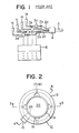
- JP-Utility Model Application 97033/1978 discloses an inspection apparatus, as shown in Fig. 1, for feeding the milk from teat cups 1a, 1b, 1c and 1d attached to cow's four teats through milk feeding pipes 2a, 2b, 2c and 2d having traps 3a, 3b, 3c and 3d respectively and further a transfer pipe 5 to a milker, wherein a pair of electrodes are installed in each of traps 3a, 3b, 3c and 3d for measuring the electric conductivity of the milk by means of an electric conductivity measuring apparatus 6.
- the electrical conductivity measurement is made on the milk sucked from each of cow's four teats to find that the teat from which the milk of a high electric conductivity value is sucked is suffering from mastitis and its degree.
- this apparatus is defective in that the milking operation is effected by vacuum suction but the milk sucked from teats is discharged intermittently. Therefore, the said milk does not flow through milk feeding pipes 2a, 2b, 2c and 2d at a fixed rate continuously, and consequently air bubbles are sometimes mingled with the milk within traps 3a, 3b, 3c and 3d. And, since due to these bubbles the milk is prevented from contacting with electrodes and further the milk once entered the traps is liable to stagnate therewithin and is difficult to be exchanged with a fresh milk, it is impossible to measure the electric conductivity thereof correctly and consequently correct inspection of the milk is also impossible.
- each of traps 3a, 3b, 3c and 3d may be contemplated to provide with an apparatus for overcoming the above defect. But, this contemplation is defective in that much trouble and expenses are required thereof.
- a milking-claw provided with inspection means for the milk sucked from cow's teats, comprising a milk collecting chamber being formed within an airtight drum housing and connected to inlets for milk formed in the upper wall of said housing and an outlet for milk formed in the lower wall of the housing characterised in that the milking-claw additionally comprises inspection chambers for milk which lie adjacent to and are partitioned off from said milk collecting chamber by means of a partition wall and into which part of the milk flowing into the milk collecting chamber through said inlets is allowed to flow; and that electrode means are attached to the wall surfaces of said inspection chambers which function to measure the electrical conductivity of the milk within the inspection chambers for milk, and a small hole is provided at a lower part of the partition wall between said collecting chamber and each of said inspection chambers to permit milk within the inspection chambers to flow into the collecting chamber.
- the aforesaid object of this invention can be achieved according to the embodiment of this invention wherein the upper wall of the drum housing comprises, a cover mounted detachably on the upper part of the side wall of said housing.
- the milk collecting chamber and inspection chambers for milk defined within the drum housing can be kept clean by removing the cover to remove the residual milk therefrom and further cleanse them.
- the aforesaid object of this invention can be achieved according to the embodiment of this invention wherein said inlets for milk are formed in the upper wall of said drum housing slanting inwardly and downwardly thereof and the lower ends thereof are arranged to open above the partition wall disposed between said collecting chamber and inspection chambers for milk to thereby let a bubble-containing milk flow down in the milk collecting chamber.
- said collecting chamber has a cylindrical partition wall and a bottom wall and is installed in an airtight fashion as well as rotatably within said drum housing, said cylindrical partition wall is provided at the lower part with an inner outlet for milk, said inspection chambers are formed as longitudinally extending spaces between the cylindrical partition wall of the collecting chamber and outwardly directed bulges in the outer wall of said drum housing, and the outer wall of said drum housing is provided with an outer outlet for milk which is designed to have communication with said inner outlet for milk when said collecting chamber is turned into a particular position.
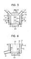
- reference numeral 11 denotes a drum housing.
- This drum housing 11 has a cylindrical outer wall 12. On the upper end of this outer wall 12 there is formed an upper flange 13. And, the inner surface of the outer wall 12 is provided with four longitudinally extending spaces 16 having a circular ark section in the peripheral direction. An outer outlet for milk 15 is formed between an optional pair of these spaces 16 and at the lower end of the outer wall 12.
- the outer peripheral surface of each space 16 is provided at the upper portion with a pair of electrodes 17 and 18 vertically at a distance. These electrodes 17 and 18 are connected to an electric conductivity measuring apparatus (not shown) of the exactly same kind as the electric conductivity measuring apparatus 6.
- a milk collecting chamber 22 is inserted in this cylindrical drum housing 11 from the bottom, said chamber 22 being defined by means of a cylindrical partition wall 19 and a bottom wall 20.
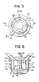
- the outer peripheral surface of the cylindrical partition wall 19 is air-tightly slide- fitted on the inner peripheral surface of the outer wall 12 present between spaces 16 and in addition the bottom wall 20 is packed with an annular packing 21 and the outer peripheral surface of said bottom wall is in an air-tight fashion slide- fitted on the inner peripheral wall of the cylindrical outer wall 12, whereby each longitudinally extending space 16 between the cylindrical partition wall 19 and outwardly directed bulges in the outer wall 12 of the drum housing may form a separate inspection chamber for milk.
- Small holes 23 are formed at the lower end of the cylindrical partition wall 19 and at a position opposite to the inspection chamber for milk 16, and an inner outlet for milk 24 is formed at a position between an optional pair of these small holes and opposite to the outer outlet for milk 15.
- the diameter of the outlet for milk 15, 24 is determined to be greater than that of the small hole 23 and the ratio is determined as referred to afterwards, namely, so that the flow speed of milk discharged from the outlet 15, 24 is greater than that of milk passing through the small hole 23 and consequently there may be no possibility of the milk within the milk collecting chamber 22 overflowing in the inspection chamber for milk 16.
- a flange 26 of a cover means 25 is placed on the upper flange 13 and thus the cover means 25 is mounted detachably on the cylindrical drum 12 by using a fitting means (not shown).
- the cover means 25 is provided with four inlets for milk 27 inclined inwardly and downwardly thereof and the lower ends of said inlets for milk open above the cylindrical partition wall 19. And, these inlets for milk 27 are connected to teat cups (not shown) of exactly the same kind as teat cups 1a, 1b, 1c and 1d.
- milk is supplied from each inlet 27 in the milking-claw.
- This milk is discharged above the cylindrical partition wall 19.
- the thus discharged milk is separated by said cylindrical partition wall.
- a part of the milk flows in the milk collecting chamber 22, and another part thereof flows in the inspection chamber for milk.16.
- the milk collecting chamber 22 is designed to turn relative to the drum housing 11. Therefore, should there be necessity of discontinuing the discharge of milk or regulating said discharge, it will suffice to turn the milk collecting chamber 22, thereby closing the outlet 15 or regulating its opening degree.
- the cleaning operation is effected through the sequence of dismantling the cover means 25 from the drum housing 11 and thereafter removing the residual milk from and cleaning the inside of the device by the use of a suitable cleaner.
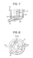
- Figs. 5 to 7 indicate the second embodiment of this invention.
- the open or close and regulation of outlet 15 is arranged to be conducted in a way of providing an outlet 15 protruded to the outside from a recess 28 formed in the center of a bottom wall 20 of a milk collecting chamber 22 and opening or closing and regulating said outlet 15 by means of a hand-operated on-off valve 30 or driving valve (not shown) incorporated in this recess 28, without resorting to the way disclosed in the first embodiment of turning the milk collecting chamber 22 relative to the drum housing 11.
- an inspection chamber for milk 16 is formed of longitudinally extending spaces between the outer wall 12 of said drum housing 12 and inwardly directed bulges formed in the cylindrical partition wall 19 and a cylindrical drum 12.
- the second embodiment as aforesaid may be carried out in exactly the same manner as the first embodiment except that the open or close and regulation of the outlet 15 is conducted in the different way as referred to above.
- the third embodiment shown in Fig. 8 is exactly the same as the second embodiment except that a means constituting the inner wall of a collecting chamber for milk 16 is not formed by a cylindrical partition 19 wall.
- the milk collecting chamber 22 is formed of an outer wall 12 of said drum housing and a bottom wall attached airtightly to this outer wall, said bottom wall is provided with an outlet 15 for milk having incorporated an on-off valve 30 therein, and said inspection chambers 16 are formed as longitudinally extending spaces formed between the outer wall of said drum housing and the partition wall 31 provided on the inner surface of this outer wall.
Landscapes
- Life Sciences & Earth Sciences (AREA)
- Animal Husbandry (AREA)
- Environmental Sciences (AREA)
- Investigating Or Analyzing Materials By The Use Of Electric Means (AREA)
- Dairy Products (AREA)
- Sampling And Sample Adjustment (AREA)
Claims (9)
Applications Claiming Priority (2)
| Application Number | Priority Date | Filing Date | Title |
|---|---|---|---|
| JP55183562A JPS5935574B2 (ja) | 1980-12-24 | 1980-12-24 | 分房乳の検査装置を具えたミルククロ− |
| JP183562/80 | 1980-12-24 |
Publications (2)
| Publication Number | Publication Date |
|---|---|
| EP0054915A1 EP0054915A1 (de) | 1982-06-30 |
| EP0054915B1 true EP0054915B1 (de) | 1985-03-13 |
Family
ID=16137968
Family Applications (1)
| Application Number | Title | Priority Date | Filing Date |
|---|---|---|---|
| EP81110529A Expired EP0054915B1 (de) | 1980-12-24 | 1981-12-17 | Melkkreuz mit Prüfvorrichtungen für die von Kuhzitzen abgesaugte Milch |
Country Status (9)
| Country | Link |
|---|---|
| US (1) | US4403568A (de) |
| EP (1) | EP0054915B1 (de) |
| JP (1) | JPS5935574B2 (de) |
| AU (1) | AU545541B2 (de) |
| CA (1) | CA1184143A (de) |
| DE (1) | DE3169304D1 (de) |
| DK (1) | DK154602C (de) |
| FI (1) | FI73571C (de) |
| NZ (1) | NZ199277A (de) |
Cited By (1)
| Publication number | Priority date | Publication date | Assignee | Title |
|---|---|---|---|---|
| DE19953700C2 (de) * | 1999-11-08 | 2002-11-28 | Ifu Gmbh | Vorrichtung zur Bestimmung des Gesundheitszustandes eines Tiereuters |
Families Citing this family (32)
| Publication number | Priority date | Publication date | Assignee | Title |
|---|---|---|---|---|
| JPS6070021A (ja) * | 1983-09-26 | 1985-04-20 | 東亜電波工業株式会社 | 搾乳装置 |
| NL8502434A (nl) * | 1985-09-04 | 1987-04-01 | Multinorm Bv | Melkinrichting. |
| GB2182534B (en) * | 1985-11-12 | 1989-10-04 | Ambic Equip Ltd | Improvements in or relating to automatic milking apparatus and methods |
| JPH0644375Y2 (ja) * | 1986-08-26 | 1994-11-16 | オリオン機械株式会社 | ミルククロ− |
| NL193553C (nl) * | 1989-02-27 | 2003-01-10 | Lely Entpr Ag | Melkinstallatie. |
| NL9001689A (nl) * | 1990-02-23 | 1991-09-16 | Lely Nv C Van Der | Inrichting voor het automatisch melken van een dier. |
| GB2257008B (en) * | 1991-04-30 | 1994-11-09 | Sidney William Simpson | Sub clinical mastitis detector and excluder |
| GB2276069B (en) * | 1992-10-09 | 1996-09-25 | Atomic Energy Authority Uk | Apparatus for and method of milking an animal |
| AU2690792A (en) * | 1992-10-09 | 1994-05-09 | United Kingdom Atomic Energy Authority | Apparatus for and method of milking an animal |
| NL9400305A (nl) * | 1994-02-28 | 1995-10-02 | Gascoigne Melotte Bv | Inrichting voor het meten van de complexe impedantie van melk, alsmede melkklauw met een dergelijke inrichting. |
| US5493995A (en) | 1994-05-16 | 1996-02-27 | Alfa Laval Agri, Inc. | Collapsing teat cup liner with tapering barrel wall |
| DE19630146C2 (de) * | 1996-07-25 | 1998-06-10 | Jakob Maier | Vorrichtung zur automatischen Milchaussonderung |
| US7277744B2 (en) * | 1999-03-22 | 2007-10-02 | Schaefer Allan L | Early detection of inflammation and infection using infrared thermography |
| US6298807B1 (en) * | 1999-04-08 | 2001-10-09 | Delaval, Inc. | Top unloading tapered barrel claw |
| RU2154373C1 (ru) * | 1999-08-16 | 2000-08-20 | Республиканский научный хозрасчетный инновационный центр агропромышленного комплекса | Устройство для дифференцированного учета молока |
| US6401655B1 (en) | 2000-04-13 | 2002-06-11 | Delaval Inc. | Milking claw with concave window |
| US6694830B2 (en) | 2001-03-03 | 2004-02-24 | Reggie Hakes | Sampling method and sampling device therefor |
| US10874084B2 (en) | 2004-06-12 | 2020-12-29 | Gea Farm Technologies, Inc. | Safety valve for a dairy system component |
| US8117989B2 (en) | 2008-06-27 | 2012-02-21 | Gea Farm Technologies, Inc. | Milk tube dome with flow controller |
| WO2008118056A1 (en) * | 2007-03-23 | 2008-10-02 | Delaval Holding Ab | A device for measuring an electrical parameter in milk and a milking apparatus including such a device |
| CN102576008A (zh) * | 2009-06-09 | 2012-07-11 | 塔图大学 | 用于检测乳腺炎和奶质量的方法以及乳腺炎传感器 |
| US20110017323A1 (en) * | 2009-07-22 | 2011-01-27 | Ewa Herbst | Method and apparatus for inline testing |
| US11723341B2 (en) | 2009-09-04 | 2023-08-15 | Gea Farm Technologies, Inc. | Safety valve for an automated milker unit backflushing and teat dip applicator system |
| US20120097107A1 (en) | 2010-02-22 | 2012-04-26 | Gea Farm Technologies, Inc. | Dairy animal milking preparation system and methods |
| ES1075767Y (es) * | 2011-06-08 | 2012-02-29 | Univ Miguel Hernandez De Elche | Dispositivo de medida de la conductividad electrica en fluidos de pequeno caudal |
| US9247708B2 (en) | 2012-12-07 | 2016-02-02 | Lauren Agrisystems, Ltd. | Dairy milking devices and methods |
| GB201309561D0 (en) | 2013-05-29 | 2013-07-10 | Quanta Fluid Solutions Ltd | Liquid conductivity measurement cell |
| US9526224B2 (en) | 2013-12-20 | 2016-12-27 | Gea Farm Technologies Gmbh | Safety valve device |
| DE102013114595B4 (de) | 2013-12-20 | 2026-01-15 | Gea Farm Technologies Gmbh | Sicherheitsventil |
| DE102016108300A1 (de) | 2016-05-04 | 2017-11-09 | Gea Farm Technologies Gmbh | Sicherheitsventil |
| WO2019090136A1 (en) | 2017-11-03 | 2019-05-09 | Gea Farm Technologies, Inc. | Automated milking system safety valve arrangement |
| RU2755437C1 (ru) * | 2020-09-07 | 2021-09-16 | Федеральное государственное бюджетное научное учреждение "Федеральный аграрный научный центр Северо-Востока имени Н.В. Рудницкого" | Способ почетвертной диагностики мастита у коров непосредственно во время доения и устройство для его осуществления |
Family Cites Families (9)
| Publication number | Priority date | Publication date | Assignee | Title |
|---|---|---|---|---|
| DE1053853B (de) * | 1957-07-31 | 1959-03-26 | Johannes Peter Larsen | Sammelstueck fuer eine Melkmaschine |
| US3014455A (en) * | 1959-10-22 | 1961-12-26 | Olander Karl Erik | Claw pieces for milking machines |
| GB1314326A (en) * | 1969-06-30 | 1973-04-18 | Nat Res Dev | Methods and apparatus for the detection of mastitis in milk animals |
| US3874337A (en) * | 1973-07-30 | 1975-04-01 | Raymond E Umbaugh | Temperature responsive system for milking apparatus |
| US3884187A (en) * | 1973-09-21 | 1975-05-20 | Chalton Electronic Services | Mastitis detector |
| CA1017001A (en) * | 1974-10-18 | 1977-09-06 | Sed Systems Ltd. | Fluid conductivity detecting means |
| CA1003900A (en) * | 1975-01-16 | 1977-01-18 | Sed Systems Ltd. | Fluid conductivity measurement apparatus |
| CS214002B1 (en) * | 1978-02-02 | 1982-04-09 | Dusan Rysanek | Apparatus for diagnostics of milk secretion failures |
| JPS5513842A (en) * | 1978-07-14 | 1980-01-31 | Eisai Co Ltd | Check unit for milking of udders |
-
1980
- 1980-12-24 JP JP55183562A patent/JPS5935574B2/ja not_active Expired
-
1981
- 1981-12-15 NZ NZ199277A patent/NZ199277A/en unknown
- 1981-12-17 DE DE8181110529T patent/DE3169304D1/de not_active Expired
- 1981-12-17 EP EP81110529A patent/EP0054915B1/de not_active Expired
- 1981-12-17 US US06/331,774 patent/US4403568A/en not_active Expired - Fee Related
- 1981-12-18 FI FI814087A patent/FI73571C/fi not_active IP Right Cessation
- 1981-12-22 DK DK570281A patent/DK154602C/da not_active IP Right Cessation
- 1981-12-23 CA CA000393129A patent/CA1184143A/en not_active Expired
- 1981-12-23 AU AU78853/81A patent/AU545541B2/en not_active Ceased
Cited By (1)
| Publication number | Priority date | Publication date | Assignee | Title |
|---|---|---|---|---|
| DE19953700C2 (de) * | 1999-11-08 | 2002-11-28 | Ifu Gmbh | Vorrichtung zur Bestimmung des Gesundheitszustandes eines Tiereuters |
Also Published As
| Publication number | Publication date |
|---|---|
| DK154602C (da) | 1989-06-05 |
| FI73571B (fi) | 1987-07-31 |
| AU545541B2 (en) | 1985-07-18 |
| EP0054915A1 (de) | 1982-06-30 |
| NZ199277A (en) | 1986-02-21 |
| DK154602B (da) | 1988-12-05 |
| JPS5935574B2 (ja) | 1984-08-29 |
| DK570281A (da) | 1982-06-25 |
| FI814087L (fi) | 1982-06-25 |
| CA1184143A (en) | 1985-03-19 |
| FI73571C (fi) | 1987-11-09 |
| JPS57105122A (en) | 1982-06-30 |
| AU7885381A (en) | 1982-07-01 |
| US4403568A (en) | 1983-09-13 |
| DE3169304D1 (en) | 1985-04-18 |
Similar Documents
| Publication | Publication Date | Title |
|---|---|---|
| EP0054915B1 (de) | Melkkreuz mit Prüfvorrichtungen für die von Kuhzitzen abgesaugte Milch | |
| US6308655B1 (en) | Device and method for milking animals | |
| FI75084C (fi) | Mjoelkningsmaskin. | |
| EP0385539B2 (de) | Melkanlage | |
| EP0836802B1 (de) | Verfahren und Gerät zum automatischen Melken von Tieren | |
| EP0096360B1 (de) | Stichprobenentnahmevorrichtung für biologische Flüssigkeiten | |
| EP1022937B1 (de) | Intelligente melkklaue | |
| ES8303015A1 (es) | Aparato para la medicion inmediata en las instalaciones ordenadoras de la cantidad de leche dada por una vaca en el curso del ordeno. | |
| DK22280A (da) | Maelkeindikator | |
| JP3129834B2 (ja) | ミルク流量計 | |
| US4523545A (en) | Apparatus for removing a milking set of a milking machine, particularly for a cow-shed | |
| US6497143B1 (en) | Container with automatically controlled discharge for continuous metering of liquid flow | |
| AU5489490A (en) | Mastitis detector for dairy cattle | |
| EP0468588A1 (de) | Gerät zum automatischen Melken von Tieren | |
| US3139856A (en) | Milking apparatus | |
| US5546892A (en) | Apparatus for separating milk and air from each other at an early stage in a pipe milking machine | |
| EP1321029B1 (de) | Vorrichtung und Zitzenbecher zum Melken von Tieren | |
| JP2010522324A (ja) | ミルクの電気パラメーターを測定するための装置及びかかる装置を含む搾乳装置 | |
| SU1410920A1 (ru) | Устройство дл доени животных | |
| US2868167A (en) | Milking and weighing apparatus | |
| US3270712A (en) | Milking machine claw | |
| US1189468A (en) | Milking-machine. | |
| SU1242064A1 (ru) | Доильный аппарат | |
| AU1011302A (en) | Apparatus for measuring and analysing fluid | |
| JP2012005420A (ja) | パイプラインミルカーの残乳回収方法 |
Legal Events
| Date | Code | Title | Description |
|---|---|---|---|
| PUAI | Public reference made under article 153(3) epc to a published international application that has entered the european phase |
Free format text: ORIGINAL CODE: 0009012 |
|
| AK | Designated contracting states |
Designated state(s): CH DE FR GB IT NL SE |
|
| 17P | Request for examination filed |
Effective date: 19821123 |
|
| ITF | It: translation for a ep patent filed | ||
| GRAA | (expected) grant |
Free format text: ORIGINAL CODE: 0009210 |
|
| AK | Designated contracting states |
Designated state(s): CH DE FR GB IT LI NL SE |
|
| REF | Corresponds to: |
Ref document number: 3169304 Country of ref document: DE Date of ref document: 19850418 |
|
| ET | Fr: translation filed | ||
| PLBE | No opposition filed within time limit |
Free format text: ORIGINAL CODE: 0009261 |
|
| STAA | Information on the status of an ep patent application or granted ep patent |
Free format text: STATUS: NO OPPOSITION FILED WITHIN TIME LIMIT |
|
| 26N | No opposition filed | ||
| ITTA | It: last paid annual fee | ||
| PGFP | Annual fee paid to national office [announced via postgrant information from national office to epo] |
Ref country code: SE Payment date: 19921109 Year of fee payment: 12 |
|
| PGFP | Annual fee paid to national office [announced via postgrant information from national office to epo] |
Ref country code: DE Payment date: 19921116 Year of fee payment: 12 |
|
| PGFP | Annual fee paid to national office [announced via postgrant information from national office to epo] |
Ref country code: FR Payment date: 19921120 Year of fee payment: 12 |
|
| PGFP | Annual fee paid to national office [announced via postgrant information from national office to epo] |
Ref country code: GB Payment date: 19921210 Year of fee payment: 12 |
|
| PGFP | Annual fee paid to national office [announced via postgrant information from national office to epo] |
Ref country code: NL Payment date: 19921231 Year of fee payment: 12 |
|
| PGFP | Annual fee paid to national office [announced via postgrant information from national office to epo] |
Ref country code: CH Payment date: 19930104 Year of fee payment: 12 |
|
| PG25 | Lapsed in a contracting state [announced via postgrant information from national office to epo] |
Ref country code: GB Effective date: 19931217 |
|
| PG25 | Lapsed in a contracting state [announced via postgrant information from national office to epo] |
Ref country code: SE Effective date: 19931218 |
|
| PG25 | Lapsed in a contracting state [announced via postgrant information from national office to epo] |
Ref country code: LI Effective date: 19931231 Ref country code: CH Effective date: 19931231 |
|
| PG25 | Lapsed in a contracting state [announced via postgrant information from national office to epo] |
Ref country code: NL Effective date: 19940701 |
|
| NLV4 | Nl: lapsed or anulled due to non-payment of the annual fee | ||
| GBPC | Gb: european patent ceased through non-payment of renewal fee |
Effective date: 19931217 |
|
| PG25 | Lapsed in a contracting state [announced via postgrant information from national office to epo] |
Ref country code: FR Effective date: 19940831 |
|
| REG | Reference to a national code |
Ref country code: CH Ref legal event code: PL |
|
| PG25 | Lapsed in a contracting state [announced via postgrant information from national office to epo] |
Ref country code: DE Effective date: 19940901 |
|
| REG | Reference to a national code |
Ref country code: FR Ref legal event code: ST |
|
| EUG | Se: european patent has lapsed |
Ref document number: 81110529.5 Effective date: 19940710 |