EP0054524A2 - Schalungs-System bestehend aus modularen Elementen für die Herstellung, Stockwerk für Stockwerk, von Bauwerken - Google Patents
Schalungs-System bestehend aus modularen Elementen für die Herstellung, Stockwerk für Stockwerk, von Bauwerken Download PDFInfo
- Publication number
- EP0054524A2 EP0054524A2 EP81830247A EP81830247A EP0054524A2 EP 0054524 A2 EP0054524 A2 EP 0054524A2 EP 81830247 A EP81830247 A EP 81830247A EP 81830247 A EP81830247 A EP 81830247A EP 0054524 A2 EP0054524 A2 EP 0054524A2
- Authority
- EP
- European Patent Office
- Prior art keywords
- casting
- forms
- storey
- walls
- construction
- Prior art date
- Legal status (The legal status is an assumption and is not a legal conclusion. Google has not performed a legal analysis and makes no representation as to the accuracy of the status listed.)
- Withdrawn
Links
Images


Classifications
-
- E—FIXED CONSTRUCTIONS
- E04—BUILDING
- E04G—SCAFFOLDING; FORMS; SHUTTERING; BUILDING IMPLEMENTS OR AIDS, OR THEIR USE; HANDLING BUILDING MATERIALS ON THE SITE; REPAIRING, BREAKING-UP OR OTHER WORK ON EXISTING BUILDINGS
- E04G15/00—Forms or shutterings for making openings, cavities, slits, or channels
- E04G15/02—Forms or shutterings for making openings, cavities, slits, or channels for windows, doors, or the like
-
- E—FIXED CONSTRUCTIONS
- E04—BUILDING
- E04G—SCAFFOLDING; FORMS; SHUTTERING; BUILDING IMPLEMENTS OR AIDS, OR THEIR USE; HANDLING BUILDING MATERIALS ON THE SITE; REPAIRING, BREAKING-UP OR OTHER WORK ON EXISTING BUILDINGS
- E04G11/00—Forms, shutterings, or falsework for making walls, floors, ceilings, or roofs
- E04G11/06—Forms, shutterings, or falsework for making walls, floors, ceilings, or roofs for walls, e.g. curved end panels for wall shutterings; filler elements for wall shutterings; shutterings for vertical ducts
- E04G11/08—Forms, which are completely dismantled after setting of the concrete and re-built for next pouring
- E04G11/10—Forms, which are completely dismantled after setting of the concrete and re-built for next pouring of elements without beams which are mounted during erection of the shuttering to brace or couple the elements
-
- E—FIXED CONSTRUCTIONS
- E04—BUILDING
- E04G—SCAFFOLDING; FORMS; SHUTTERING; BUILDING IMPLEMENTS OR AIDS, OR THEIR USE; HANDLING BUILDING MATERIALS ON THE SITE; REPAIRING, BREAKING-UP OR OTHER WORK ON EXISTING BUILDINGS
- E04G11/00—Forms, shutterings, or falsework for making walls, floors, ceilings, or roofs
- E04G11/06—Forms, shutterings, or falsework for making walls, floors, ceilings, or roofs for walls, e.g. curved end panels for wall shutterings; filler elements for wall shutterings; shutterings for vertical ducts
- E04G11/08—Forms, which are completely dismantled after setting of the concrete and re-built for next pouring
- E04G11/12—Forms, which are completely dismantled after setting of the concrete and re-built for next pouring of elements and beams which are mounted during erection of the shuttering to brace or couple the elements
-
- E—FIXED CONSTRUCTIONS
- E04—BUILDING
- E04G—SCAFFOLDING; FORMS; SHUTTERING; BUILDING IMPLEMENTS OR AIDS, OR THEIR USE; HANDLING BUILDING MATERIALS ON THE SITE; REPAIRING, BREAKING-UP OR OTHER WORK ON EXISTING BUILDINGS
- E04G13/00—Falsework, forms, or shutterings for particular parts of buildings, e.g. stairs, steps, cornices, balconies foundations, sills
Definitions
- the present invention relates to a casting form system comprising modular elements, system which permits to carry out a non-conventional system of construction of multi-stored buildings for civil houses, in which the stories of each building will be constructed, storey by storey, and wherein each storey comprises curtain walls embodying reinforced concrete pillars, while the floors are made by the use of prefabricated elements and will be constructed only after that all the walls embodying the pillars have been completed, i.e. at the same time in which takes place the casting of the concrete for the construction of the horizontal carrying beams and of the floor slabs.
- the casting form system of this invention enables to carry out a non-conventional construction method, according to which a building is constructed, storey by storey, in such a way that in each storey the pillars are constructed according to the conventional technics and with standard mixes, while the curtain walls and the inner main walls are constructed on the place by means of special thermo-insulating and/or sound proofing, lightweight materials, said walls embodying the pillars which are integrally embedded therein.
- peripheral walls and, in general, at least an inner longitudinal main wall consist of carrying walls and are totally or partially prefabricated, or they are constructed according to the standard construction technics, but also intermediate pillars can be provided, when required.
- the floors can be also constructed at least partially by means of prefabricated floor elements. All the construction methods known up to the date have the inconveniences that they are very expensive and that they require a complicate equipment for the hoisting and the transport of materials and apparatus, thus requiring very high running costs and also a large ' skilled labor.
- the present invention relates to a construction method which is very simple to be carried out and which requires workers of a modest skill and the use of a simple equipment which includes at least a crane or the like, at least an apparatus for the hoisting and the distribution of the concrete or other mixes, necessary for the construction of the pillars, the beams or girders the slabs and the curtain walls, since the building will be constructed, storey by storey, so that before the construction of the floors and of the curb beams of each storey, the work can be carried out entirely in the open. Therefore the crane or cranes can be used also for the transport and for co-operating in the assembly of all the form members as well as of other required equipments and devices.
- the casting form system of the present invention comprises: first modular forms for the construction of the portions of the peripheral walls comprised between two ° windows and/or window-doors; second modular forms for the construction of inner main walls or of the peripheral walls without windows or provided only with doors, said first and second modular forms also including or co-operating with support means which are or can be separated from the modular members of the first and second modular casting forms and which are designed to support the floors and the horizontal carrying beams during their casting and setting and which remain in their operative position until the hardening of the concrete or the like, while the other components of said casting forms are disassembled and removed just after the first phase of the setting of the concrete or the like.
- For the casting of the pillars made of standard concrete can be used box-like tubular probe-like forms of an extractable type, or special forms designed to be left in the place.
- the casting form system of this invention enables to carry out a non-conventional construction method, according to which the pillars are at least partially embedded into the curtain walls and are constructed at the same time as these walls.
- said curtain walls are not constructed by means of prefabricated blocks or panels, but, on the contrary, they are casted on the place so as to be integraly connected to the pillars, by employing a lightweight, thermo-insulating and soundproofing mix.
- the mixture which is the object of the Italian Patent Application No. 50086-A/80 filed on November 5, 1980 of the same Applicant, said mixture including cement, foamed clay, ground tuff or the like and vermiculite.
- casting forms by means, of which said method is carried out, can be used for the construction of each storey of a building and also can be used again for the construction of other buildings, since they can be quickly and easily adapted to building projects of different types of houses for civil use, either of intensive or semi-intensive character.
- the pillars which are placed in the peripheral walls and which are more- exposed to the changes of the climatic conditions are perfectly insulated from the atmosphere on the thermic point of view, because they are entirely embedded into the mixture which is used for obtaining the curtain walls, thus making said carrying structures extremely protected against any steam imbibition, thus, more in particular, preventing any rusting of the reinforcing irons thereof.
- a building can be costructed which has a total resistance to the static and dynamic stresses which is clearly higher than that of the buildings constructed according to the conventional methods or of those which are constructed according to the methods of a partial or total prefabrication.
- the construction method which can be carried out with the use of the casting form system of this invention, permits the simultaneous casting of two different mixes, i.e. the standard concrete for the construction of the reinforced concrete pillars and beams, and the mix which serves for obtaining the curtain walls, as, for istance, the mix which has been disclosed in the aforementioned Italian Patent Application.
- the constructive method which can be performed with the use of the casting form system of this invention, can be considered as particularly adapted to be appl,ied for the construction of building in the seismic zones.
- the Figure 1 shows diagrammatically the plan view of the casting form system provided for the construction of a typical storey of a multi-stored building, which storey will be obtained completed of the peripheral walls, the center main wall as well as of the pillars and of the beams designed to carry the respective floor; this latter will be constructed by means of prefabricated plate elements or by means of latticed metal girders and juxtaposed hollow clay blocks, tiles or the like.
- each storey it is only necessary to construct the partition walls for defining the various rooms of each suite of rooms, as well as to perform the finishing operation of the building.
- two areas are provided which are separated by a' longitudinal center main wall 1, said areas being divided in rooms so as to form two suite of rooms or flats, each having an entrance door 6 which opens in the stairs (not shown).
- the longitudinal peripheral walls 2 are provided with openings 3 for windows or window-doors, while the transversal peripheral wall 4 does not include any window opening and the opposite transversal wall 5, adjacent to the stairs comprises the entrance doors 6 of the two respective flats.
- the configuration of the typical storey is not binding.
- Said casting form system comprises casting forms, generally indicated 7 in Figure 1, of a box-like prismatic shape, which are composed by an inner wall element 8 and by an outer wall element 8 which will define respectively the inner and outer surfaces of each wall portion of the peripheral wall 2 of the building, while said form 7 together with an other form 7 defines an opening 3 for a window or a window-door, also providing the engaging seats for supporting the prefabricated member 10 forming the window sill (only one of which has been shown by slotted lines-in Figure 1) and for the window lintel members 11 which are so shaped so as to define also the space adapted to receive the caisson housing the roller which supports a roller blind or the like.
- the main walls 1, the peripheral walls 4 without doors and the peripheral walls 5 provided with doors 6 opened on the stairs and optional the portions of the outer walls 2 near the corners are constructed using casting forms generally marked 12 and consisting of pairs of plate wall elements 13 supported in a mutual and spaced-, relationship by vertical side portal frames of a disassemblable type.
- a cement mix 58 which is lightweight, thermo-insulating and sound proofing
- each casting form 7 comprises two box-like main elements 8 and 9 designed to define the outer facing surface and the inner facing surface respectively of each wall portion 2, as well as the reveal or doorport of each opening 3 for a window or a window-door respectively.
- Each of the box-like elements 8 and 9 comprises a central portion formed by a metal plate 20 provided with an outer peripheral stiffening frame 17 and with outer horizontal stiffening ribs 18.
- Each of the vertical sides of a metal plate 20 of the part 9 of each form 7 extends towards the opening 3 with a vertical flange 21, the vertical edge of which is bent towards said opening 3 so as to form a channel-like end portion 21A of a U-shaped cross section ( Figure 4), the bottom wall of which is parallel to the plate 20.
- 21A is cut out horizontally at the level of the lowest part of the prefabricated window lintel member 11 so as to form an edge 19 on which can rest the respective end of said lintel member 11.
- Said lintel member 11 consists of a prefabricated shaped body on the back of the lowest part of which ( Figure 2) a longitudinal recess 11C is provided which opens downwardly and rearwardly so as to define a space for housing the caisson of a roller blind or the like, while at the upper part of the lintel member 11, this latter forms an outer vertical longitudinal flange 11A so as to create on the back thereof a shoulder 11B which serves to define the bottom surface of a curb beam 23 during the casting of the superposed portion of said beam 23, at the zone, where said beam passes over of an opening 3, so that the flange 11A and the shoulder 11B act in this zone as form elements for that portion of beam 23 during the casting of the beam 23 in the zone placed over an opening 3; on the contrary, the outer surface of the other portions of the beam 23 are shaped by the upper portions of the outer plates 20 of the form elements 9, which, for such a purpose, are higher than the plates 20 of each inner form element 8, thus acting as form elements for the casting of said outer side surface of the
- Each inner form element 8 along each vertical side extends sidewards with a shaped flange 24, 24A, 24B of a slightly less height than that of the respective plate 20 which is integral therewith and which is shaped so as to define the surface of the splay of the opening 3 and the reveal, if required, on which will abut the casing mounted into the opening 3 adapted to receive a window-door for the access to a terrace placed at the level of the room ground.
- the flange 21, 21A will be substituted, from its lower end until the height of the window sill, by a flange 22A, and the lower portion 24A of the flange 24, 24A is substituted by a flange 22B.
- the two flanges 22A and 22B serve to form in the wall 2 a vertical rib of a triangular cross section, extending outwardly from the wall portion 3 on each side of the opening 3: in said ribs will be inserted the vertical edges provided with complemental longitudinal grooves 10A (Figure 1) of each prefabricated window sill panel 10 and which will be mounted inserting this latter from the top of said ribs and moving it donwwardly.
- the flanges 22A are shaped according to the same configuration as that of the flanges 21A, 21B but they extend much more towards the opening 3.
- the flanges 21, 21A or 22A support with their end portions the latch locking devices 25 and 25A respectively which abut on the shoulder 24B of each flange 24, so as connect the two main parts 8 and 9 of the form 7 in their operative position, in which the interengaging parts are seal connected to one another.
- the forms 7 are held in their correct operative position with regard of the ground plane of the floor 26 which covers the storey placed below by means of pairs of lower horizontal metal beams 27 pivotally inserted at.36 into hollow tubular members 28 extending outwardly from the vertical sides of the frame 17 into the space 3, near the lower end of each form element 9.
- a tubular member 30 to which a rod 31 is hinged ( Figures 2 and 5): in said rod 31 a screw coupling 32 of an adjustable length is inserted; at the other end the rod 31 is hinged to the beam 27 in proximity of its inner end.
- the screw couplings 32 permit to obtain the perfect verticality of the plates 20 of the form elements 8 and 9, while during the disassembling step they permit.to cause the respective form element 9 to be inclined outwardly for making easier its hooking to the hook of the hoisting crane.
- each column 29 is mounted with a head 33 having beveled side surfaces, said head 33 being mounted in a freely rotatable manner on the upper end of the column 29, the lower end of which is screwed on a base 29A ( Figure 3) which is connected by means of removable connections 34 to the adjacent beam 27.
- Each column 29 is supported with the interposition of adjusting means by pairs of stirrups 35A and 35B, respectively supported by the flanges 21 and 24 by means of arms 63A and 63B respectively ( Figure 5).
- each form element 8 Upon each form element 8 is mounted an inverted U-shaped section iron 37 which forms an inner channel having its cavity facing downwardly and into which are received the shaped heads 33 of the adjacent columns 29 which serve to carry said section iron 37, which will have the side wall 37A positioned in the front of the wall 2 to be constructed, said side wall 37A having such a height that it can be introduced into the form part 8 with its lower portion in contact with the upper portion of the inner surface of the plate 20 of the form member 8 so that said wall 37 can define the inner surface facing the rooms of the adjacent curb beam 23, while the horizontal portion 37B of the iron 37 forms a horizontal shoulder on which can rest the ends of the plate members 26A provided for the construction of the carrying floor 26.
- the section iron 37 may consist also of lengths of iron, which are assembled one after the other.
- a plate 64 is also mounted for defining all the inner vertical surface of the beam 23, if necessary, in the zones of the peripheral walls 2, where lintel members 11 are mounted.
- the height of the upper, edge of the flanges 25 of the form elements 9 is less than that of the plate 20 thereof so as to permit that the flange 37A of the iron 37 can be always in contact with the inner surface of each plate 20 and of the surface of the prefabricated lintel member 11 facing the rooms in the zone where an opening 3 has to be formed in said peripheral wall 2.
- the longitudinal main wall 1 acts also as a wall which separate two flats one from another, so that it is necessary that this wall must be made thermo-insulating and sound proofing.
- This wall 1 must also embody pillars 16 and thus it will be constructed using the casting form, generally marked 12 and which comprises, as has been already said, pairs of parallel plates 13 and two juxtaposed disassemblable vertical portal-like frames 14.
- the plates 13 are stiffened by outer horizontal inserted ribs 38 and along their vertical sides edges 39 are provided which are bent at right angle outwardly.
- the pairs of plates 13 are held spaced away from one another at a predetermined distance by means of said portal frames 14, each of which includes a pair of body plate sides 40, having specularly identical shapes of a birectangle trapezoid, having horizontal bases and of a height less than that of the wall to be constructed.
- the oblique side of said trapezoidal plate 40 is positioned outwardly, while the vertical side thereof, which is set at right angle with regard to the two bases,- extends on each side so as to form two short vertical and complanar flanges 41, set at right angle to the plane of the body sides 40, and which are designed to abut against the inner surfaces of the two adjacent plates 13.
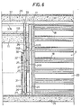
- each body side 40 On each body side 40 a plurality of horizontal slots 42 are arranged, positioned each upon the other and designed to receive wedge locking members 43 ( Figure 7) for locking the plates 13 against the flanges 41 of the two subsequent portal frames 12.
- the two shaped body sides 40, 41 which are part of each portal frame 14 are connected to one another by trnaversal bars 44 which pass through slots arranged on the flanges 41 and which respectively face in pair each other in a perfectly aligned relationship.
- On the portions of the bars 44 which will be placed inside each form 12 are mounted protection pieces 45 of an inverted U-shaped in cross section, made of plastics, in particular, polystyrene, which have the task to prevent any contact between each bar 44 and the concrete 58 which will be casted into said casting form 12.
- the bars 44 are fastened to the body sides 40 in their operative position by locking screws 55. In such a way the bars 44 define the width of the wall 1 to be constructed by means of a casting form 12.
- a device 46 ( Figures 7 and 8) which is able to support, at an adjustable height, an inverted, U-shaped section iron 47 operatively equivalent to and having the same task as that of each aforementioned section iron 37 associated with the casting forms 7, and which has thus a cross section of a similar shape, thus comprising an inner side flange 47A, the lower edge portion of which is designed to contact the inner surface of the flanges 41 of the portal frames 14 and which is supported by the heads 48A of the vertical bars 48 of the devices 46 which are mounted on one outer side of the casting form 12, while another identical section iron 47 will be mounted in a specularly identical position near the other outer side of the casting form 12 and which is, in turn, supported by the bars 48 of the respective devices 46, which are mounted near the opposite sides of
- section irons 47 have the same task as that of the section irons 37 they are not better described in detail and operation. These irons 47 will serve to define the longitudinal sides of a longitudinal beam 23 parallel to the peripheral curb beams 23 in the case of the main wall 1,-or said section irons 47 serve to define the inner side surface of the end portions of the longitudinal curb beams 23 in the case of walls 2 as well as of the transversal beams 23 of the walls 4 and 5, while at the same time they serve in this case to support also the end portions of the floor elements 26A.
- Each device 46 comprised a bar 48 sliding vertically within guiding members and the end portion 48A of which enters the channel opened downwardly of the respective inverted U-shaped iron 47; said bar 48, by means of a lever 49 pivotally mounted about a pin 50 supported by the body side 40 can be moved up or down by a threaded rod 51 and a control threaded nut 52.
- inner corner members 53 and outer corner members 54 are provided, which are connected, by means of portal frames 14, to modified end forms 7A.
- Each form 7A at the end thereof which is adjacent to an opening 3, is shaped like the end portions of the casting forms 7, while at the opposite end it ends only with the end frames 17 similar to those of the plates 20 of the form elements 8 and 9 of the casting forms 7 and therefore can be employed and fixed in the same manner, as the plates 13 of the casting forms 12.
- pairs of plates 13a (not shown), which are selected between the plates of the appropriate modular .lenghts, can be mounted by means of a portal frames 14 and can be juxtaposed between a casting form 7A and the corner members 53 and 54, whenever the adjacent corner of the peripheral wall 2 is placed at distance from said corner greater than the length of a casting form 7A.
- two angled pieces 53 are used on the inside of said wall 4 or 5, while in order to define the outer surface of said walls 4 and 5 in this zone can be used the plates 13.
- each exctractable form 15 is provided at its upper part with connections 65: or, as an alternative, casting forms 56 are used, designed to be left on the place.
- Said forms 15 or 56 serve for the construction of the reinforced concrete pillars 16, after having previously inserted therein the respective reinforcing irons, which, of course, will be fixedly connected to those of the pillars 16, of the storey placed below, the end portions of which extend upwardly from the upper surface of the floor of said formerly constructed storey in correspondance of the walls 1,2,4 and 5 and in the corner zones or in the union zones of the walls.
- the standard concrete 57 will be casted into the probe-like extractable forms 15 or in the forms 56 designed to remain in place, which can substitute the forms 15.
- Each form 56 consists of a prismatic metal tubular body having short lenghts of iron 56A fastened to its outer surfaces and extending horizontally towards the outside ( Figure 9).
- the mix 58 designed to obtain the curtain walls, said mix enclosing the whole pillar body 16.
- the casting of the mixes is carried out until the level of the shoulders 11B of the lintel members 11 is reached.
- the optional extractable forms 15 are removed, lifting each form 15 by means of a crane, the hook of which is anchored to the upper connections 65 of said form 15.
- the to mixes 57 and 58 can interpenetrate one into the other in the joint areas, so as to create a monolithic connection between the pillars 16 and the curtain walls.
- the short lengths of the irons 56A ensure the interconnection between the curtain walls and the pillars 16 embedded therein.
- the reinforcing irons for the construction of the horizontal girders or beams 23 are mounted the prefabricated elements 26A of the floor, (the end portions of which rest on the irons 37 and 47 respectively) and then optionally the reinforcing irons for said floor 26.
- the construction of the floor is temporarily suspended, so as to create.in each floor, which is being constructed, a large passageway 60 for the purpose which will be hereinafter illustrated.
- the reinforcing irons of the prefabricated elements 26A of the floor 26, which extend outwardly from said elements 26A will be connected with the reinforcing irons of the beams 23. Then is casted the concrete 57 which serves for the construction of the beams 23 and the slab 59 which covers the floor 26, except in the zones in which have been created the passageways 60, where no floor is yet constructed.
- the screw couplings 32 can be actuated so as to increase their length of such an extend that the outer form elements 9 can be inclined outwardly and can be more easily hooked to the hook of a crane for performing their lifting and transport up to be mounted in their operative positions upon the just constructed floor 26, so that they can be ready to be used for the construction of the subsequent storey.
- the outer members of those casting forms 12, which are used for the construction of the walls 4 and 5 and of the possible end portions of the walls 2 will be necessary to install outer work bridges, for performing the disassembly of the outer plates 13 of the casting forms 12, previously removing the locking wedges 43.
- the inner components of the forms 7 and the inner plates 13 of the casting forms 12 thereof will be disassembled and than transported at first underneath the respective passageway 60, where they can be hooked to the crane hook which can enter until the inner space designed to form each suite of rooms or flat, passing through the passageway 60 which has been left on each floor 26 for such a purpose. Then the window sills will be obtained, where required, by the insertion, with a sliding dowwards movement, of the prefabricated window sill members 10, l0A with their vertical grooved edges 10A sliding into the respective ribs of the casting forms (7, 7A).
- the beams 23 and the floors 26 will be supported until the hardening of the mixes 57 and 58 has been attained, by means of the inverted-U irons 37 and 47 mounted on the heads 33 of the columns 29 and respectively on the heads 48A of the bars 48 which are part of the devices 46 mounted on the portal frames 14. On the contrary, the corner elements 53 and 54 will be left yet in their operative positions.
- the columns 29 are caused to rotate about their axes with regard of their bases 29A, so that their heads 33 can lower.
- the ends 48A of the bars 48 of the devices 46 are caused to be lowered, so that the U-shaped irons 37 and 47 can be moved downwardly, this being separated from the beams 23 and the floor 26.
- each floor 26 will be completed in correspondance of the passageway areas 60, while on the already constructed floor portions can be mounted the casting form system for the construction of a new storey.
- casting form system of this invention could be also used in the case of the construction of buildings having walls and pillars obtained by any standard reinforced or not reinforced concrete or other suitable mixes.
Landscapes
- Engineering & Computer Science (AREA)
- Architecture (AREA)
- Mechanical Engineering (AREA)
- Civil Engineering (AREA)
- Structural Engineering (AREA)
- Forms Removed On Construction Sites Or Auxiliary Members Thereof (AREA)
- Load-Bearing And Curtain Walls (AREA)
Applications Claiming Priority (2)
| Application Number | Priority Date | Filing Date | Title |
|---|---|---|---|
| IT5039780 | 1980-12-17 | ||
| IT50397/80A IT1127964B (it) | 1980-12-17 | 1980-12-17 | Casseratura ad elementi modulari per la costruzione a piani di un edificio per civile abitazione |
Publications (2)
| Publication Number | Publication Date |
|---|---|
| EP0054524A2 true EP0054524A2 (de) | 1982-06-23 |
| EP0054524A3 EP0054524A3 (de) | 1983-05-18 |
Family
ID=11272889
Family Applications (1)
| Application Number | Title | Priority Date | Filing Date |
|---|---|---|---|
| EP81830247A Withdrawn EP0054524A3 (de) | 1980-12-17 | 1981-12-17 | Schalungs-System bestehend aus modularen Elementen für die Herstellung, Stockwerk für Stockwerk, von Bauwerken |
Country Status (2)
| Country | Link |
|---|---|
| EP (1) | EP0054524A3 (de) |
| IT (1) | IT1127964B (de) |
Cited By (4)
| Publication number | Priority date | Publication date | Assignee | Title |
|---|---|---|---|---|
| RU2157878C2 (ru) * | 1996-02-13 | 2000-10-20 | Черных Александр Георгиевич | Опалубка для возведения монолитных сооружений |
| CN108871889A (zh) * | 2018-03-28 | 2018-11-23 | 王珍珍 | 一种小型抗折强度制样盒结构 |
| CN110607905A (zh) * | 2019-10-14 | 2019-12-24 | 中建二局第二建筑工程有限公司 | 一种全钢支撑加固模板体系及施工方法 |
| CN114482524A (zh) * | 2021-12-03 | 2022-05-13 | 中建三局集团有限公司 | 实现逐层平移波浪悬挑造型的包络式模板及其施工方法 |
Families Citing this family (1)
| Publication number | Priority date | Publication date | Assignee | Title |
|---|---|---|---|---|
| CN113047338B (zh) * | 2021-03-26 | 2024-04-26 | 上海浦东混凝土制品有限公司 | 一种拼接较为稳固的预制综合管廊 |
Family Cites Families (8)
| Publication number | Priority date | Publication date | Assignee | Title |
|---|---|---|---|---|
| FR742964A (de) * | 1933-03-21 | |||
| FR938380A (fr) * | 1946-12-30 | 1948-09-13 | Perfectionnements aux dispositifs de coffrages amovibles utilisés pour les constructions en béton | |
| DE803565C (de) * | 1949-11-01 | 1951-04-05 | Ernst Pfleiderer Dr Ing | Schalung mit an Gleitschienen verschiebbar gefuehrten Schalungstafeln |
| BE552986A (de) * | 1955-11-29 | |||
| FR1562247A (de) * | 1968-02-22 | 1969-04-04 | ||
| DE1813131A1 (de) * | 1968-12-06 | 1970-06-25 | Mahrdt & Kreis Kg Fabrik Fuer | Rolladen-Einbaukasten |
| FR2260683A1 (en) * | 1974-02-08 | 1975-09-05 | Sacreste Henry | Window bay construction device - has lost shuttering jambs and lintel support |
| CA1059490A (en) * | 1976-04-27 | 1979-07-31 | Jack R. Tooley | Apparatus for use in buildings |
-
1980
- 1980-12-17 IT IT50397/80A patent/IT1127964B/it active
-
1981
- 1981-12-17 EP EP81830247A patent/EP0054524A3/de not_active Withdrawn
Cited By (5)
| Publication number | Priority date | Publication date | Assignee | Title |
|---|---|---|---|---|
| RU2157878C2 (ru) * | 1996-02-13 | 2000-10-20 | Черных Александр Георгиевич | Опалубка для возведения монолитных сооружений |
| CN108871889A (zh) * | 2018-03-28 | 2018-11-23 | 王珍珍 | 一种小型抗折强度制样盒结构 |
| CN110607905A (zh) * | 2019-10-14 | 2019-12-24 | 中建二局第二建筑工程有限公司 | 一种全钢支撑加固模板体系及施工方法 |
| CN114482524A (zh) * | 2021-12-03 | 2022-05-13 | 中建三局集团有限公司 | 实现逐层平移波浪悬挑造型的包络式模板及其施工方法 |
| CN114482524B (zh) * | 2021-12-03 | 2023-09-22 | 中建三局集团西南有限公司 | 实现逐层平移波浪悬挑造型的包络式模板及其施工方法 |
Also Published As
| Publication number | Publication date |
|---|---|
| IT1127964B (it) | 1986-05-28 |
| IT8050397A0 (it) | 1980-12-17 |
| EP0054524A3 (de) | 1983-05-18 |
Similar Documents
| Publication | Publication Date | Title |
|---|---|---|
| US2053873A (en) | Building structure | |
| EP0055504B1 (de) | Verfahren und Strukturelement für den Aufbau eines Gebäudes und auf diese Art ausgebildetes Gebäude | |
| US2043697A (en) | Building structure | |
| US1501288A (en) | Concrete structure | |
| US2373409A (en) | Building construction | |
| CA2038524C (en) | Form and method of constructing a wall from pourable concrete material | |
| US3474580A (en) | Prefabricated buildings and their assembly | |
| EP0054524A2 (de) | Schalungs-System bestehend aus modularen Elementen für die Herstellung, Stockwerk für Stockwerk, von Bauwerken | |
| EP0065793B1 (de) | Bewehrungskonstruktion für Eisenbetongebäude | |
| USRE21905E (en) | Building construction | |
| WO1992002701A1 (en) | A method of wall construction | |
| KR102636240B1 (ko) | 테이블폼 시스템 및 그 해체방법 | |
| KR100361047B1 (ko) | 건축물 구축용 거푸집 | |
| US1924414A (en) | Building structure | |
| EP0048870A1 (de) | Vorrichtung zur Herstellung vorgefertigter Wandelelemente zur Vollmontage von Häusern | |
| US2139907A (en) | Building construction | |
| RU2065907C1 (ru) | Каркас здания, здание и способ возведения здания | |
| US4455270A (en) | Construction process including slab sliding support and comprising simultaneous wall erection | |
| DE829660C (de) | Bauweise mit Beton-Fertigteilen | |
| RU2353735C2 (ru) | Способ возведения монолитных каркасных зданий | |
| WO2003097950A2 (en) | In-situ construction of concrete building | |
| SU1067174A1 (ru) | Скольз ша опалубка | |
| JP2990216B2 (ja) | 鉄筋コンクリート造建物の構築工法 | |
| JPH02236325A (ja) | 超高層建築物の構築方法 | |
| SU796363A1 (ru) | Скольз ща опалубка |
Legal Events
| Date | Code | Title | Description |
|---|---|---|---|
| PUAI | Public reference made under article 153(3) epc to a published international application that has entered the european phase |
Free format text: ORIGINAL CODE: 0009012 |
|
| AK | Designated contracting states |
Designated state(s): AT BE CH DE FR GB LU NL SE |
|
| PUAL | Search report despatched |
Free format text: ORIGINAL CODE: 0009013 |
|
| AK | Designated contracting states |
Designated state(s): AT BE CH DE FR GB LI LU NL SE |
|
| STAA | Information on the status of an ep patent application or granted ep patent |
Free format text: STATUS: THE APPLICATION IS DEEMED TO BE WITHDRAWN |
|
| 18D | Application deemed to be withdrawn |
Effective date: 19840122 |