EP0054080B1 - Muscle exercising device - Google Patents
Muscle exercising device Download PDFInfo
- Publication number
- EP0054080B1 EP0054080B1 EP80107845A EP80107845A EP0054080B1 EP 0054080 B1 EP0054080 B1 EP 0054080B1 EP 80107845 A EP80107845 A EP 80107845A EP 80107845 A EP80107845 A EP 80107845A EP 0054080 B1 EP0054080 B1 EP 0054080B1
- Authority
- EP
- European Patent Office
- Prior art keywords
- spring
- training apparatus
- muscle training
- arm
- spring chamber
- Prior art date
- Legal status (The legal status is an assumption and is not a legal conclusion. Google has not performed a legal analysis and makes no representation as to the accuracy of the status listed.)
- Expired
Links
Images


Classifications
-
- A—HUMAN NECESSITIES
- A63—SPORTS; GAMES; AMUSEMENTS
- A63B—APPARATUS FOR PHYSICAL TRAINING, GYMNASTICS, SWIMMING, CLIMBING, OR FENCING; BALL GAMES; TRAINING EQUIPMENT
- A63B21/00—Exercising apparatus for developing or strengthening the muscles or joints of the body by working against a counterforce, with or without measuring devices
- A63B21/15—Arrangements for force transmissions
- A63B21/151—Using flexible elements for reciprocating movements, e.g. ropes or chains
- A63B21/153—Using flexible elements for reciprocating movements, e.g. ropes or chains wound-up and unwound during exercise, e.g. from a reel
-
- A—HUMAN NECESSITIES
- A63—SPORTS; GAMES; AMUSEMENTS
- A63B—APPARATUS FOR PHYSICAL TRAINING, GYMNASTICS, SWIMMING, CLIMBING, OR FENCING; BALL GAMES; TRAINING EQUIPMENT
- A63B21/00—Exercising apparatus for developing or strengthening the muscles or joints of the body by working against a counterforce, with or without measuring devices
- A63B21/02—Exercising apparatus for developing or strengthening the muscles or joints of the body by working against a counterforce, with or without measuring devices using resilient force-resisters
- A63B21/023—Wound springs
- A63B21/025—Spiral springs with turns lying substantially in plane surfaces
-
- A—HUMAN NECESSITIES
- A63—SPORTS; GAMES; AMUSEMENTS
- A63B—APPARATUS FOR PHYSICAL TRAINING, GYMNASTICS, SWIMMING, CLIMBING, OR FENCING; BALL GAMES; TRAINING EQUIPMENT
- A63B21/00—Exercising apparatus for developing or strengthening the muscles or joints of the body by working against a counterforce, with or without measuring devices
- A63B21/15—Arrangements for force transmissions
- A63B21/151—Using flexible elements for reciprocating movements, e.g. ropes or chains
- A63B21/154—Using flexible elements for reciprocating movements, e.g. ropes or chains using special pulley-assemblies
-
- A—HUMAN NECESSITIES
- A63—SPORTS; GAMES; AMUSEMENTS
- A63B—APPARATUS FOR PHYSICAL TRAINING, GYMNASTICS, SWIMMING, CLIMBING, OR FENCING; BALL GAMES; TRAINING EQUIPMENT
- A63B21/00—Exercising apparatus for developing or strengthening the muscles or joints of the body by working against a counterforce, with or without measuring devices
- A63B21/40—Interfaces with the user related to strength training; Details thereof
- A63B21/4027—Specific exercise interfaces
- A63B21/4033—Handles, pedals, bars or platforms
- A63B21/4035—Handles, pedals, bars or platforms for operation by hand
-
- A—HUMAN NECESSITIES
- A63—SPORTS; GAMES; AMUSEMENTS
- A63B—APPARATUS FOR PHYSICAL TRAINING, GYMNASTICS, SWIMMING, CLIMBING, OR FENCING; BALL GAMES; TRAINING EQUIPMENT
- A63B23/00—Exercising apparatus specially adapted for particular parts of the body
- A63B23/035—Exercising apparatus specially adapted for particular parts of the body for limbs, i.e. upper or lower limbs, e.g. simultaneously
- A63B23/03516—For both arms together or both legs together; Aspects related to the co-ordination between right and left side limbs of a user
- A63B23/03533—With separate means driven by each limb, i.e. performing different movements
-
- A—HUMAN NECESSITIES
- A63—SPORTS; GAMES; AMUSEMENTS
- A63B—APPARATUS FOR PHYSICAL TRAINING, GYMNASTICS, SWIMMING, CLIMBING, OR FENCING; BALL GAMES; TRAINING EQUIPMENT
- A63B23/00—Exercising apparatus specially adapted for particular parts of the body
- A63B23/035—Exercising apparatus specially adapted for particular parts of the body for limbs, i.e. upper or lower limbs, e.g. simultaneously
- A63B23/12—Exercising apparatus specially adapted for particular parts of the body for limbs, i.e. upper or lower limbs, e.g. simultaneously for upper limbs or related muscles, e.g. chest, upper back or shoulder muscles
- A63B23/1209—Involving a bending of elbow and shoulder joints simultaneously
-
- A—HUMAN NECESSITIES
- A63—SPORTS; GAMES; AMUSEMENTS
- A63B—APPARATUS FOR PHYSICAL TRAINING, GYMNASTICS, SWIMMING, CLIMBING, OR FENCING; BALL GAMES; TRAINING EQUIPMENT
- A63B21/00—Exercising apparatus for developing or strengthening the muscles or joints of the body by working against a counterforce, with or without measuring devices
- A63B21/40—Interfaces with the user related to strength training; Details thereof
- A63B21/4027—Specific exercise interfaces
- A63B21/4033—Handles, pedals, bars or platforms
Definitions
- the invention relates to a muscle training device from a cross-shaped frame with two horizontal arms, in which a spring with a bow handle is arranged on each horizontal arm.
- a known muscle training device for training the upper body and arm muscles consists of a horizontal frame, on the crossbar of which two rollers containing guides are arranged, over which a cable runs, which carries a bow handle at one end and at the other end with a resistance-forming weight is connected (US-A 3115339).
- the device is operated with both arms when standing, whereby the weights are raised to different heights using the cable.
- Gym equipment for performing gymnastic exercises are also known.
- a known device of this type which is operated when lying down, contains a cable that runs over a roller guide arranged at the head end of a bed and ends in bow handles, into which the user grips with one foot each (US-A1240809). The user performs stretching and flexing movements with the legs in opposite phases, and the resistance is formed by the other leg of the user.
- a known gymnastics device (US-A 1 390 095) of the type mentioned contains a cross-shaped frame with two horizontal arms, which start from an adjustable cross head and each carry slidable brackets with a coil spring and a handle. The handles are connected to an electrical voltage source.
- DE-A2304048 discloses a training device in which a drive spring contained in a housing and adjustable to selected preloads can be unwound by means of a tension band against the force of the drive spring. This in particular enables stretching training between the user's limbs; the device can also be attached to fixed counter bearings such as door handles.
- a known gymnastics device constructed in the manner of an expander contains two chambers in a housing, in each of which a rotatable shaft is mounted. Each shaft is under the action of a spiral spring and is provided with a drum on which a cable pull with a handle is wound. Each cable pull is guided between two parallel rollers at the outlet of the housing.
- the housing is attached to a wall.
- a known coil spring arrangement (Desoutter Bros. Ltd., Hendon, London NW9, model No. 4-D) contains a spring housing which receives a coil spring in a spring chamber which can be closed by a cover.
- the spring chamber has a tensioning element acting on the central axis of the spiral spring for setting a variable preload of the spiral spring and a cable pull which can be unwound from the drum against a force which can be rotated relative to the central axis.
- the previously known devices are either only intended for the training of certain muscle areas through limited types of movement exercises or serve predominantly as gymnastic working devices which, through their operation, are intended to cause the user to lose weight.
- muscle training requires specific sequences of movement exercises that are tailored to the muscles to be influenced.
- these sequences of movement exercises have to be carried out on different devices.
- different devices have to be purchased for different movement exercises, which results in an undesirably large outlay and also an undesirably large amount of space.
- This also has the disadvantage that it is not always possible to carry out the necessary sequence of movement exercises without interruption when changing between the different devices.
- Such interruptions in muscle activity call into question the success of the movement exercises, since the muscles in question are to be maintained in the favorable blood circulation state caused by their actuation throughout the entire sequence of the program of the coordinated movement exercises.
- the object of the invention is to provide a muscle training device of the type mentioned at the outset, which allows the largest possible variety of movement exercises on this one device and thereby an uninterrupted sequence of entire programs of movement exercises.
- this object is achieved in that at least one spring chamber is arranged on each horizontal and each vertical arm and in each spring chamber a spiral spring with a predominantly linear characteristic is contained, and in that each spiral spring is connected to a relaxation mechanism and a cable pull and each spring chamber has an edge-free one Guide for the associated cable is assigned.
- Such a device enables a large number of movement exercises in a confined space, if only for the fact that the cable pulls to be operated run to both sides and up and down, so that the movement exercises are performed even with different postures can be led.
- the device can be easily expanded by providing a seat or a couch so that the movement exercises can also be carried out with different body positions.
- a particular advantage is also achieved by the springs, which form the resistors instead of weights in the device according to the invention.
- This advantage is based on the fact that the springs ensure that the tension and relaxation movements of the muscles each take place against a uniformly changing counterforce, while when using weights the relaxation movement generally only results in a slackening of the muscle tensed for lifting and one back movement determined by the fall of the weight.
- the uniformity of the tension and relaxation movement is promoted by the fact that the springs have a predominantly linear characteristic, so that the spring elongation is always changed by the same amount regardless of the respective tension state of the spring by certain forces.
- the guide for the cable has a frame which is separate from the spring chamber and the frame is connected to a carrier which can be displaced along the horizontally extending arm. In this way it is easy to reproducibly set different starting positions for movement exercises on the horizontally extending arms without the need to adjust the spring chamber.
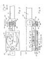
- the muscle training device consists of a frame 1 with four arms 2, 3, 4, 5 of approximately 1 m in length that run perpendicular to one another in one plane.
- the arms 2 and 3 go vertically and the arms 4 and 5 horizontally from a first connecting part 6, which is diamond-shaped in the exemplary embodiment shown, but can have any other suitable shape.
- the arms 2, 3, 4, 5 consist of square tubes made of steel, which are welded to the first connecting part 6 made of sheet steel.
- the arms 2, 3, 4, 5 and the first connecting part 6 can also consist of any other suitably stable material, whereby they are connected to one another in the most appropriate manner.
- the arms 2 and 3 are provided at the ends with a second or third connecting part 7 or 8 which (see FIG. 2) protrude parallel to one another from the arms 2 and 3 in the same directions.
- the connecting part 7 consists of a profile part made of sheet steel which tapers towards the free end and is welded to the arm 2. However, it can also consist of any other suitably stable material with any other shape that can be used for this application.
- the same applies to the third connecting member 8, which in the exemplary embodiment shown likewise consists of a square tube made of steel with cross members and is welded to the arm 3. From the free end of the third connecting member 8, a base plate 9 of semicircular shape protrudes, which tapers towards its edge. On this footplate 9, the user can support himself with his feet in an advantageous manner for certain movement exercises.
- the arm 3 also carries, directly below the first connecting member 6, a backrest 10, on which a user of the device can be supported, who is on a seat bridging the third connecting member 8 or a correspondingly positioned couch.
- the armrest part 10 consists of a cushion element 11 of rectangular basic shape on the side facing the user. It is attached to a carrier 12 which projects from the arm 3 parallel to the third connecting part 8 and over which a hollow holding element 13 extends telescopically, which projects from the side of the cushion element 11 facing away from the padded side.
- the cushion element 11 is fastened to the carrier 12 by a locking screw 14.
- the locking screw 14 extends through a threaded bore in the holding element 13 into a threaded bore on the circumference of the carrier 12, which can be provided with a guide groove in order to facilitate the reinsertion of the locking screw 14.
- the armrest part 10 can be pivoted about the axis of the carrier 12.
- the backrest part 10 also has a support element 15 running parallel to the holding element 13, which rests on the surface of the arm 3 facing the backrest part 10 with an elastic support 16.
- the armrest part 10 can also have a different shape and can be pivotably attached to the arm 3 by other known means.
- a rod 17 is arranged on the arm 3, which runs parallel to the horizontal arms 4 and 5 and is provided at both ends with handles, not shown. On this rod 17, the user of the Support the muscle training device when performing certain movement exercises.
- the arms 2, 3, 4, 5 carry, on the side facing the user, spring chambers 20 which are essentially of the same design and are described in detail below.
- spring chambers 20 directed towards the center are arranged vertically next to one another and fastened to the opposite side surfaces of the free end of the second connecting member 7 by welding or the like.
- two forwardly directed spring chambers 20 are arranged horizontally next to one another and fastened by welding or the like to the opposite free ends of the cross members of the third connecting member 8.
- FIGS. 3 and 4 show sectional views of the spring chamber 20 in their arrangement on the arm 5.
- the spring chamber 20 is fastened to the arm 5 with one broad side and closed by a cover 21 on the opposite broad side.
- the cover 21 occupies only part of the broad side; on the inside, the cover 21 carries clamping angles 22 on one narrow side and clamping tongues (not shown) on the other narrow side, which engage under a part which is permanently connected to the spring chamber 20.
- the cover 21 also has an opening for a holding pin 23 protruding from the opposite broad side of the spring chamber 20, on the free end of which a handle 24 is screwed on.
- the spring chamber 20 can also be closed by a differently held cover, if necessary also by a hinged cover.
- two supports 24 ′ arranged at a distance from one another protrude from the same broad side into the interior of the spring chamber 20, which are formed by welded-on angles in the exemplary embodiment shown.
- the spring chamber 20 accommodates a spring housing 25, which contains a spiral spring (not shown) and, at one end, engages with the eye 26 over the holding pin 23.
- the spring housing 25 is supported on the supports 24 'and thus lies with one side just below the cover 21.
- a central axis 27 passes through the spring housing 25 and is arranged at the end facing the cover 21 for engagement with a tensioning member 28, which by a Breakthrough in the cover 21 protrudes outwards and carries a handwheel 29.
- the handwheel 29 and the cover 21 can optionally carry markings by means of which the rotational position of the handwheel 29 can be determined.
- the central axis 27 is held by a retaining spring 30, which is wound around a part of the central axis 27 protruding from the spring housing 25 and one end of which is anchored in a holder 31, while the other end forms a trigger member 32 .
- the space 24 'in the spring chamber 20 determines the space for receiving these parts of the spring housing 25.
- a trigger element 33 aligned with the trigger member 32 extends through a narrow side of the spring chamber 20 and, in the exemplary embodiment shown, is a rod 36 which is provided with an operating button 34 at the outer end and is guided in a straight guide 35. From the end of the spring housing 25 facing away from the eye 26, a cable 37 runs through a passage 38 of the spring chamber 20, which carries a bow handle 39 at its free end.
- the spring housing 25 contains a coil spring; the coil spring arrangement including the design and mounting of the central axis 27 is commercially available (Desoutter Bros. Ltd., Hendon, London NW 9; model No. 4-D) and is therefore not described in detail. To better explain the function of the coil spring arrangement, however, it should be mentioned that the central axis 27 can be rotated relative to the spring housing 25 and that one end of the coil spring is anchored to the central axis 27 and the other end to the inner circumference of a drum which is rotatably mounted on the central axis 27 is and on the outer circumference of the cable 37 is wound.
- the spiral spring can therefore be tensioned by unwinding the cable 37 when the drum rotates relative to the central axis 27, but also by rotating the central axis 27 by means of the handwheel 29 relative to the drum.
- the coil spring By turning the central axis 27, the coil spring is biased relative to the drum, so that the unwinding of the cable pull from the drum requires a greater force.
- the coil spring can be relaxed by attacking the trigger element 33 on the trigger member 32; the central axis 27 is free from the action of the retaining spring 30, so that the central axis can rotate under the action of the coil spring until it relaxes relative to the drum.
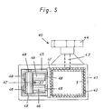
- the cable 37 emerging from the bushing 38 of the spring chamber 20 passes through a guide 40 which is separate from the spring chamber 20 and which is also shown in detail in FIG.
- the guide 40 is contained in a carrier 41 of generally rectangular cross-section, which is open on two opposite sides and is divided by a partition 42 '.
- a carrier 41 of generally rectangular cross-section, which is open on two opposite sides and is divided by a partition 42 '.
- two adjacent chambers are formed, one of which is provided with a lining 42 which is slidable on the material of the arm 5 and with a locking screw 43 with a handle 44.
- the lining 42 can also be dispensed with; in such a case, the locking screw 43 should be made of a material that does not damage the arm 5 when tightened.
- the other chamber contains the actual guide 40 from one in the chamber firmly inserted frame 45, which receives the guide elements and is open to the passage 38 in the spring chamber 20 and to the bow handle 39 of the cable 37 running through the guide 40.
- the guide elements are formed by two parallel guide rollers 46 facing the bushing 38, which are arranged horizontally and one below the other and between which the cable 37 is guided, and a guide roller 47 which partially overlaps them and runs perpendicular thereto, on the circumference of which the cable 37 is guided is.
- the guide roller 47 is located on the side of the frame 45 facing away from the spring chamber 20.
- Each guide roller 46, 47 is rotatably mounted on the frame 45.
- pins 48 serve for this purpose, which are inserted into the frame 45 and attached to the bearings (not shown) in the end faces of the guide rollers 46, 47.
- the walls of the frame 45, in which the guide roller 47 is mounted are provided with cutouts 49 which extend in depth to a part of the circumference of the guide rollers 46, and the guide roller 47 is arranged so that its periphery protrudes outward beyond the frame 45.
- the design of the guide 40 results in an almost friction-free and thus resistance-free guidance of the cable 37 so that the force of the coil spring has to be overcome to move it.
- the arrangement of the guide rollers 46, 47 allows the cable 37 to be moved in addition to a movement parallel to the arm 5 in three mutually perpendicular directions, namely with respect to the arm 5 upwards, downwards and forwards without that there would be some edge contact when moving in these directions or their combination.
- the guide rollers shown or their storage other guide elements can also be used, provided that the same guide properties are achieved.
- the bow handles 39 can be brought into any suitable starting position, with the cable 37 being free of tension in any selected starting position or being loaded with a certain preload.
- the guide 40 or the frame 45 in these arms is formed in one piece with the spring chambers 20, the frame 45 directly adjoining the narrow side of the spring chamber 20 provided with the bushing 38.
- the guides 40 are of identical design and are therefore not shown and described in detail.
- the guides 40 enable the cable pulls 37 to move in parallel to the arms 2, 3 in parallel and in at least three directions perpendicular to one another and their combinations, namely with respect to the arms 2 and 3 to the right and left and to the front and below or forwards and upwards.
- Another rod 17, also provided with handles, is attached to the arm 2 on the side of the spring chambers 20 facing the user.
- the frame 1 is fastened to a wall with fastening means.
- the device described above enables a targeted training of selected muscles through a sequence of certain movement exercises. These movement exercises are carried out against the force of springs and therefore in both directions against a resistance which can be varied in the same way in both directions of movement, the design and arrangement of the springs with differently adjustable preloads enabling extensive, easily controllable adjustment of the force required for movement training.
- the arrangement and number of spring chambers allows uninterrupted execution of entire sequences of movement exercises in different postures and body positions, since the frame 1 can be easily combined with a separate seat or a corresponding couch.
- Such movement exercises generally do not serve to cause the user to lose weight through physical work, but to tighten muscles and their tissues that have become slack due to disuse or illness.
- the exercises on the muscle training device therefore primarily serve to improve the posture and thus also the body shape of the user, they can also be therapeutically valuable in relieving tension in muscles or restoring their ability to work.
Abstract
Description
Die Erfindung betrifft ein Muskeltrainingsgerät aus einem kreuzförmigen Gestell mit zwei waagerechten Armen, bei dem an jedem waagerechten Arm eine Feder mit einem Bügelgriff angeordnet ist.The invention relates to a muscle training device from a cross-shaped frame with two horizontal arms, in which a spring with a bow handle is arranged on each horizontal arm.
Ein bekanntes Muskeltrainingsgerät zum Training der Oberkörper- und Armmuskulatur besteht aus einem reckartigen Gestell, an dessen Querbalken zwei Rollen enthaltende Führungen angeordnet sind, über die jeweils ein Seilzug verläuft, der an einem Ende einen Bügelgriff trägt und am anderen Ende mit einem einen Widerstand bildenden Gewicht verbunden ist (US-A 3115339). Das Gerät wird im Stand mit beiden Armen bedient, wobei die Gewichte mittels des Seilzuges auf verschiedene Höhen angehoben werden.A known muscle training device for training the upper body and arm muscles consists of a horizontal frame, on the crossbar of which two rollers containing guides are arranged, over which a cable runs, which carries a bow handle at one end and at the other end with a resistance-forming weight is connected (US-A 3115339). The device is operated with both arms when standing, whereby the weights are raised to different heights using the cable.
Es sind ferner Gymnastikgeräte zur Ausführung gymnastischer Übungen bekannt. Ein bekanntes Gerät dieser Art, das im Liegen bedient wird, enthält einen Seilzug, der über eine am Kopfende einer Liege angeordnete Rollenführung verläuft und in Bügelgriffen endet, in die der Benutzer mit jeweils einem Fuss greift (US-A1240809). Der Benutzer führt jeweils gegenphasige Streck- und Beugebewegungen mit den Beinen durch, und der Widerstand wird von dem jeweils anderen Bein des Benutzers gebildet.Gym equipment for performing gymnastic exercises are also known. A known device of this type, which is operated when lying down, contains a cable that runs over a roller guide arranged at the head end of a bed and ends in bow handles, into which the user grips with one foot each (US-A1240809). The user performs stretching and flexing movements with the legs in opposite phases, and the resistance is formed by the other leg of the user.
Bei einem weiteren bekannten Gymnastikgerät (US-A2397054) dieser Art, das in angelehnter Stellung bedient wird, sind zwei über Kreuz verlaufende Seilzüge vorgesehen, die über eine Schraubenfeder mit jeweils einer Fussraste verbunden sind und über eine Rollenführung zu Bügelgriffen verlaufen. Der Benutzer ergreift die Bügelgriffe mit den Händen und arbeitet so gegen die von den abgefederten Fussrasten gebildeten Widerstände.In another known gymnastics device (US-A2397054) of this type, which is operated in the ajar position, two cross-running cables are provided, which are connected to a footrest via a helical spring and extend to bow handles via a roller guide. The user grips the bow handles with his hands and works against the resistance created by the spring-loaded footrests.
Ein bekanntes Gymnastikgerät (US-A 1 390 095) der eingangs genannten Art enthält ein kreuzförmiges Gestell mit zwei waagerechten Armen, die von einem verstellbaren Kreuzkopf ausgehen und jeweils daran verschiebbare Halterungen mit einer Schraubenfeder und einem Handgriff tragen. Die Handgriffe sind an eine elektrische Spannungsquelle angeschlossen.A known gymnastics device (US-A 1 390 095) of the type mentioned contains a cross-shaped frame with two horizontal arms, which start from an adjustable cross head and each carry slidable brackets with a coil spring and a handle. The handles are connected to an electrical voltage source.
Durch die DE-A2304048 ist ein Trainingsgerät bekannt, bei dem eine in einem Gehäuse enthaltene und auf ausgewählte Vorspannungen einstellbare Triebfeder mittels eines Zugbandes gegen die Kraft der Triebfeder abgewickelt werden kann. Dadurch wird insbesondere ein Strecktraining zwischen den Gliedmassen des Benutzers ermöglicht; das Gerät kann aber auch an festen Gegenlagern wie Türklinken befestigt werden.DE-A2304048 discloses a training device in which a drive spring contained in a housing and adjustable to selected preloads can be unwound by means of a tension band against the force of the drive spring. This in particular enables stretching training between the user's limbs; the device can also be attached to fixed counter bearings such as door handles.
Ein nach Art eines Expanders konstruiertes bekanntes Gymnastikgerät (CH-A 263 306) enthält in einem Gehäuse zwei Kammern, in denen jeweils eine drehbare Welle gelagert ist. Jede Welle steht unter der Wirkung einer Spiralfeder und ist mit einer Trommel versehen, auf die ein mit einem Handgriff versehener Seilzug aufgewickelt ist. Jeder Seilzug ist am Ausgang des Gehäuses zwischen zwei parallelen Rollen geführt. Das Gehäuse wird an einer Wand befestigt.A known gymnastics device (CH-A 263 306) constructed in the manner of an expander contains two chambers in a housing, in each of which a rotatable shaft is mounted. Each shaft is under the action of a spiral spring and is provided with a drum on which a cable pull with a handle is wound. Each cable pull is guided between two parallel rollers at the outlet of the housing. The housing is attached to a wall.
Eine bekannte Spiralfederanordnung (Desoutter Bros. Ltd., Hendon, London NW9, Modell Nr. 4-D) enthält ein eine Spiralfeder aufnehmendes Federgehäuse in einer durch einen Deckel verschliessbaren Federkammer. Die Federkammer weist ein an der Mittelachse der Spiralfeder angreifendes Spannglied zur Einstellung einer variablen Vorspannung der Spiralfeder und einen Seilzug auf, der gegen die Kraft der Spiralfeder von einer relativ zur Mittelachse verdrehbaren Trommel abwickelbar ist.A known coil spring arrangement (Desoutter Bros. Ltd., Hendon, London NW9, model No. 4-D) contains a spring housing which receives a coil spring in a spring chamber which can be closed by a cover. The spring chamber has a tensioning element acting on the central axis of the spiral spring for setting a variable preload of the spiral spring and a cable pull which can be unwound from the drum against a force which can be rotated relative to the central axis.
Die vorbekannten Geräte sind entweder nur für das Training bestimmter Muskulaturbereiche durch begrenzte Arten von Bewegungsübungen vorgesehen oder dienen überwiegend als gymnastische Arbeitsgeräte, die durch ihre Betätigung eine Gewichtsabnahme des Benutzers bewirken sollen. Im allgemeinen erfordert ein Muskeltraining aber gezielte, auf die jeweils zu beeinflussenden Muskeln abgestimmte Folgen von Bewegungsübungen. Nach dem Stand der Technik müssen diese Folgen von Bewegungsübungen an unterschiedlichen Geräten ausgeführt werden. Das bedeutet, dass für verschiedene Bewegungsübungen verschiedene Geräte angeschafft werden müssen, wodurch ein unerwünscht grosser Anschaffungsaufwand entsteht und auch ein unerwünscht grosser Raumbedarf verursacht wird. Weiter ergibt sich dadurch der Nachteil, dass es nicht immer gelingt, die notwendige Folge von Bewegungsübungen beim Wechsel zwischen den verschiedenen Geräten unterbrechungslos durchzuführen. Solche Unterbrechungen der Muskeltätigkeit stellen aber den Erfolg der Bewegungsübungen in Frage, da die betreffenden Muskeln während der gesamten Abfolge des Programms der aufeinander abgestimmten Bewegungsübungen in dem durch ihre Betätigung hervorgerufenen günstigen Durchblutungszustand erhalten bleiben sollen.The previously known devices are either only intended for the training of certain muscle areas through limited types of movement exercises or serve predominantly as gymnastic working devices which, through their operation, are intended to cause the user to lose weight. In general, however, muscle training requires specific sequences of movement exercises that are tailored to the muscles to be influenced. According to the prior art, these sequences of movement exercises have to be carried out on different devices. This means that different devices have to be purchased for different movement exercises, which results in an undesirably large outlay and also an undesirably large amount of space. This also has the disadvantage that it is not always possible to carry out the necessary sequence of movement exercises without interruption when changing between the different devices. Such interruptions in muscle activity, however, call into question the success of the movement exercises, since the muscles in question are to be maintained in the favorable blood circulation state caused by their actuation throughout the entire sequence of the program of the coordinated movement exercises.
Dementsprechend besteht die Aufgabe der Erfindung darin, ein Muskeltrainingsgerät der eingangs genannten Art zu schaffen, das eine möglichst umfassende Vielzahl von Bewegungsübungen an diesem einen Gerät und dadurch einen unterbrechungslosen Ablauf ganzer Programme von Bewegungsübungen gestattet.Accordingly, the object of the invention is to provide a muscle training device of the type mentioned at the outset, which allows the largest possible variety of movement exercises on this one device and thereby an uninterrupted sequence of entire programs of movement exercises.
Erfindungsgemäss wird diese Aufgabe dadurch gelöst, dass an jedem waagerechten und jedem senkrechten Arm mindestens eine Federkammer angeordnet ist und in jeder Federkammer eine Spiralfeder mit überwiegend linearer Charakteristik enthalten ist, und dass jede Spiralfeder mit einem Entspannungsmechanismus und einem Seilzug verbunden ist und jeder Federkammer eine kantenfreie Führung für den zugehörigen Seilzug zugeordnet ist.According to the invention this object is achieved in that at least one spring chamber is arranged on each horizontal and each vertical arm and in each spring chamber a spiral spring with a predominantly linear characteristic is contained, and in that each spiral spring is connected to a relaxation mechanism and a cable pull and each spring chamber has an edge-free one Guide for the associated cable is assigned.
Ein solches Gerät ermöglicht eine Vielzahl von Bewegungsübungen auf engstem Raum allein schon dadurch, dass die zu betätigenden Seilzüge nach beiden Seiten und nach oben und unten verlaufen, so dass die Bewegungsübungen auch bei unterschiedlichen Körperhaltungen ausgeführt werden können. Darüber hinaus lässt sich das Gerät ohne weiteres durch Beistellen eines Sitzes oder einer Liege so erweitern, dass die Bewegungsübungen auch bei unterschiedlichen Körperstellungen vorgenommen werden können. Ein besonderer Vorteil wird dabei noch durch die Federn erzielt, die anstelle von Gewichten bei dem erfindungsgemässen Gerät die Widerstände bilden. Dieser Vorteil beruht darauf, dass durch die Federn erreicht wird, dass die Spannungs-und Entspannungsbewegungen der Muskeln jeweils gegen eine sich gleichmässig verändernde Gegenkraft erfolgen, während bei der Verwendung von Gewichten die Entspannungsbewegung im allgemeinen nur in einer Erschlaffung des zum Heben angespannten Muskels und einer durch den Fall des Gewichtes bestimmten Rückbewegung besteht. Die Gleichmässigkeit der Spannungs- und Entspannungsbewegung wird dabei dadurch gefördert, dass die Federn eine überwiegend lineare Charakteristik haben, so dass die Federdehnung unabhängig vom jeweiligen Spannungszustand der Feder durch bestimmte Kräfte immer um gleiche Beträge verändert wird.Such a device enables a large number of movement exercises in a confined space, if only for the fact that the cable pulls to be operated run to both sides and up and down, so that the movement exercises are performed even with different postures can be led. In addition, the device can be easily expanded by providing a seat or a couch so that the movement exercises can also be carried out with different body positions. A particular advantage is also achieved by the springs, which form the resistors instead of weights in the device according to the invention. This advantage is based on the fact that the springs ensure that the tension and relaxation movements of the muscles each take place against a uniformly changing counterforce, while when using weights the relaxation movement generally only results in a slackening of the muscle tensed for lifting and one back movement determined by the fall of the weight. The uniformity of the tension and relaxation movement is promoted by the fact that the springs have a predominantly linear characteristic, so that the spring elongation is always changed by the same amount regardless of the respective tension state of the spring by certain forces.
Es ist dabei weiterhin vorteilhaft, wenn die Führung für den Seilzug einen von der Federkammer getrennten Rahmen aufweist und der Rahmen mit einem entlang des waagerecht verlaufenden Arms verschiebbaren Träger verbunden ist. Auf diese Weise lassen sich leicht unterschiedliche Ausgangsstellungen für Bewegungsübungen an den waagerecht verlaufenden Armen reproduzierbar einstellen, ohne dass dazu eine Verstellung der Federkammer erforderlich ist.It is also advantageous if the guide for the cable has a frame which is separate from the spring chamber and the frame is connected to a carrier which can be displaced along the horizontally extending arm. In this way it is easy to reproducibly set different starting positions for movement exercises on the horizontally extending arms without the need to adjust the spring chamber.
Ein Ausführungsbeispiel der Erfindung ist in den Abbildungen dargestellt und wird nachfolgend an Hand der Bezugszeichen im einzelnen erläutert.An embodiment of the invention is shown in the figures and is explained in detail below with reference to the reference numerals.
Es zeigen:
- Fig. 1 eine Gesamtansicht des erfindungsgemässen Muskeltrainingsgerätes;
- Fig. 2 eine Seitenansicht des Muskeltrainingsgerätes nach Fig. 1;
- Fig. 3 einen Längsschnitt durch eine Federkammer und eine davon getrennte Führung für den Seilzug bei dem Muskeltrainingsgerät nach Fig. 1;
- Fig. 4 einen Querschnitt durch die Federkammer und die Führung nach Fig. 3;
- Fig. 5 einen Querschnitt durch einen Träger für eine Führung nach Fig. 3.
- 1 shows an overall view of the muscle training device according to the invention;
- FIG. 2 shows a side view of the muscle training device according to FIG. 1;
- 3 shows a longitudinal section through a spring chamber and a separate guide for the cable in the muscle training device according to FIG. 1;
- 4 shows a cross section through the spring chamber and the guide according to FIG. 3;
- 5 shows a cross section through a carrier for a guide according to FIG. 3rd
Das Muskeltrainingsgerät besteht nach der Gesamtansicht in Figur 1 aus einem Gestell 1 mit vier in einer Ebene senkrecht zueinander verlaufenden Armen 2, 3, 4, 5 von ca. 1 m Länge. Die Arme 2 und 3 gehen senkrecht und die Arme 4 und 5 waagerecht von einem ersten Verbindungsteil 6 aus, das in dem dargestellten Ausführungsbeispiel rautenförmig ausgebildet ist, aber jede andere geeignete Form haben kann. In dem gezeigten Ausführungsbeispiel bestehen die Arme 2, 3, 4, 5 aus Vierkantrohren aus Stahl, die mit dem aus Stahlblech bestehenden ersten Verbindungsteil 6 verschweisst sind. Die Arme 2, 3, 4, 5 und das erste Verbindungsteil 6 können aber auch aus jedem anderen, geeignet stabilen Material bestehen, wobei sie in der jeweils zweckmässigsten Weise miteinander verbunden sind.According to the overall view in FIG. 1, the muscle training device consists of a
Die Arme 2 und 3 sind an den Enden mit einem zweiten bzw. dritten Verbindungsteil 7 bzw. 8 versehen, die (vgl. Figur 2) nach gleichen Richtungen hin parallel zueinander von den Armen 2 und 3 vorstehen. Das Verbindungsteil 7 besteht aus einem sich nach dem freien Ende hin verjüngenden Profilteil aus Stahlblech, das mit dem Arm 2 verschweisst ist. Es kann aber auch aus jedem anderen, geeignet stabilen Material mit jeder anderen, für diesen Anwendungszweck brauchbaren Form bestehen. Gleiches gilt für das dritte Verbindungsglied 8, das in dem gezeigten Ausführungsbeispiel ebenfalls von einem Vierkantrohr aus Stahl mit Querträgern besteht und mit dem Arm 3 verschweisst ist. Von dem freien Ende des dritten Verbindungsgliedes 8 steht eine Fussplatte 9 von halbkreisförmigem Grundriss vor, die sich zu ihrem Rand hin verjüngt. An dieser Fussplatte 9 kann sich der Benutzer mit den Füssen in für bestimmte Bewegungsübungen vorteilhafter Weise abstützen.The
Der Arm 3 trägt weiterhin unmittelbar unterhalb des ersten Verbindungsgliedes 6 ein Lehnteil 10, an dem sich ein Benutzer des Gerätes abstützen kann, der sich auf einem das dritte Verbindungsglied 8 überbrückenden Sitz oder einer entsprechend aufgestellten Liege befindet. Das Lehnteil 10 besteht aus einem Polsterelement 11 von rechteckiger Grundform an der dem Benutzer zugekehrten Seite. Es ist an einem Träger 12 befestigt, der von dem Arm 3 parallel zum dritten Verbindungsteil 8 vorsteht und über den ein hohles Halteelement 13 teleskopartig übergreift, das von der der gepolsterten Seite abgewandten Seite des Polsterelementes 11 vorsteht. Durch eine Feststellschraube 14 ist das Polsterelement 11 an dem Träger 12 befestigt. Die Feststellschraube 14 verläuft durch eine Gewindebohrung in dem Halteelement 13 in eine Gewindebohrung am Umfang des Trägers 12, die mit einer Führungsnut versehen sein kann, um die Wiedereinführung der Feststellschraube 14 zu erleichtern. Nach Lösen der Feststellschraube 14 lässt sich das Lehnteil 10 um die Achse des Trägers 12 verschwenken. Das Lehnteil 10 weist ferner ein parallel zu dem Halteelement 13 verlaufendes Stützelement 15 auf, das der dem Lehnteil 10 zugekehrten Fläche des Arms 3 mit einer elastischen Auflage 16 anliegt. Das Lehnteil 10 kann aber auch eine andere Form haben und mit anderen bekannten Mitteln schwenkbar an dem Arm 3 befestigt sein.The
Unterhalb des Lehnteils 10 ist an dem Arm 3 ein Stab 17 angeordnet, der parallel zu den waagerechten Armen 4 und 5 verläuft und an beiden Enden mit nicht dargestellten Handgriffen versehen ist. An diesem Stab 17 kann sich der Benutzer des Muskeltrainingsgerätes bei der Durchführung bestimmter Bewegungsübungen abstützen.Below the armrest part 10 a
Die Arme 2, 3, 4, 5 tragen an der dem Benutzer zugekehrten Seite Federkammern 20, die im wesentlichen gleich ausgebildet sind und nachfolgend im einzelnen beschrieben werden. An dem senkrecht verlaufenden Arm 2 sind zwei zur Mitte gerichtete Federkammern 20 senkrecht nebeneinander angeordnet und durch Verschweissen oder dergl. an den gegenüberliegenden Seitenflächen des freien Endes des zweiten Verbindungsgliedes 7 befestigt. Am senkrecht verlaufenden Arm 3 sind zwei nach vorn gerichtete Federkammern 20 waagerecht nebeneinander angeordnet und durch Verschweissen oder dgl. an den gegenüberliegenden freien Enden der Querträger des dritten Verbindungsgliedes 8 befestigt. An den waagerecht verlaufenden Armen 4 und 5 ist jeweils eine zur Mitte gerichtete Federkammer 20 in einer zur Ebene des Gestells 1 parallelen Ebene angeordnet und durch Verschweissen oder dergl. an dem jeweiligen Arm 4 bzw. 5 befestigt.The
Figuren 3 und 4 zeigen Schnittansichten der Federkammer 20 in ihrer Anordnung an dem Arm 5. Die Federkammer 20 ist mit einer Breitseite an dem Arm 5 befestigt und an der gegenüberliegenden Breitseite durch einen Deckel 21 verschlossen. In dem gezeigten Ausführungsbeispiel nimmt der Deckel 21 nur einen Teil der Breitseite ein; an der Innenseite trägt der Deckel 21 an einer Schmalseite Klemmwinkel 22 und an der anderen Schmalseite (nicht gezeigte) Klemmzungen, die unter ein unlösbar mit der Federkammer 20 verbundenes Teil greifen. Der Deckel 21 weist ferner einen Durchbruch für einen von der gegenüberliegenden Breitseite der Federkammer 20 vorstehenden Haltestift 23 auf, auf dessen freies Ende ein Handgriff 24 aufgeschraubt ist. Die Federkammer 20 kann aber auch durch einen anders gehalterten Deckel, gegebenenfalls auch durch einen Klappdeckel verschliessbar sein. Ausser dem Haltestift 23 stehen zwei im Abstand voneinander angeordnete Auflagen 24' von der gleichen Breitseite her in das Innere der Federkammer 20 vor, die in dem gezeigten Ausführungsbeispiel von aufgeschweissten Winkeln gebildet werden.FIGS. 3 and 4 show sectional views of the
Die Federkammer 20 nimmt ein Federgehäuse 25 auf, das eine (nicht gezeigte) Spiralfeder enthält und an einem Ende mit einem Auge 26 über den Haltestift 23 greift. Das Federgehäuse 25 stützt sich an den Auflagen 24' ab und liegt so mit einer Seite dicht unterhalb des Deckels 21. Eine Mittelachse 27 durchsetzt das Federgehäuse 25 und ist an dem dem Deckel 21 zugekehrten Ende zum Eingriff mit einem Spannglied 28 eingerichtet, das durch einen Durchbruch im Deckel 21 nach aussen vorsteht und ein Handrad 29 trägt. Das Handrad 29 und der Deckel 21 können gegebenenfalls Markierungen tragen, mittels derer die Drehstellung des Handrads 29 feststellbar ist. An der anderen Seite des Federgehäuses 25 ist die Mittelachse 27 durch eine Haltefeder 30 gehaltert, die um ein aus dem Federgehäuse 25 vorstehendes Teil der Mittelachse 27 gewunden ist und deren eines Ende in einer Halterung 31 verankert ist, während das andere Ende ein Auslöseglied 32 bildet. Durch die Auflagen 24' wird in der Federkammer 20 der Raum zur Aufnahme dieser Teile des Federgehäuses 25 bestimmt. Durch eine Schmalseite der Federkammer 20 hindurch erstreckt sich ein zu dem Auslöseglied 32 ausgerichtetes Auslöseelement 33, das im gezeigten Ausführungsbeispiel eine am Aussenende mit einem Bedienungsknopf 34 versehene, in einer Geradführung 35 geführte Stange 36 ist. Aus dem von dem Auge 26 abgewandten Ende des Federgehäuses 25 heraus verläuft ein Seilzug 37 durch eine Durchführung 38 der Federkammer 20, der an seinem freien Ende einen Bügelgriff 39 trägt.The
Das Federgehäuse 25 enthält eine Spiralfeder; die Spiralfederanordnung ist einschliesslich der Ausbildung und Halterung der Mittelachse 27 im Handel erhältlich (Desoutter Bros. Ltd., Hendon, London NW 9; Modell Nr.4-D) und wird daher nicht im einzelnen beschrieben. Zur besseren Erläuterung der Funktion der Spiralfederanordnung sei jedoch erwähnt, dass die Mittelachse 27 gegenüber dem Federgehäuse 25 verdrehbar ist und dass ein Ende der Spiralfeder an der Mittelachse 27 und das andere Ende am inneren Umfang einer Trommel verankert ist, die auf der Mittelachse 27 drehbar gelagert ist und auf deren Aussenumfang der Seilzug 37 aufgewickelt ist. Die Spiralfeder kann daher durch Abwickeln des Seilzuges 37 bei Verdrehung der Trommel gegenüber der Mittelachse 27 gespannt werden, jedoch auch durch Verdrehung der Mittelachse 27 mittels des Handrades 29 gegenüber der Trommel. Durch die Verdrehung der Mittelachse 27 wird die Spiralfeder gegenüber der Trommel vorgespannt, so dass die Abwicklung des Seilzuges von der Trommel eine grössere Kraft erfordert. In jedem Fall kann aber die Spiralfeder durch Angriff des Auslöseelementes 33 an dem Auslöseglied 32 entspannt werden; dabei wird die Mittelachse 27 von der Einwirkung der Haltefeder 30 frei, so dass sich die Mittelachse unter Einwirkung der Spiralfeder bis zu deren Entspannung gegenüber der Trommel verdrehen kann.The
Der aus der Durchführung 38 der Federkammer 20 austretende Seilzug 37 durchsetzt eine von der Federkammer 20 getrennte Führung 40, die im einzelnen auch in Figur 5 dargestellt ist. Die Führung 40 ist in einem Träger 41 von allgemein rechteckigem Querschnitt enthalten, der an zwei gegenüberliegenden Seiten offen und durch eine Trennwand 42' unterteilt ist. Dadurch werden zwei nebeneinander liegende Kammern gebildet, deren eine mit einer auf dem Material des Arms 5 gleitfähigen Auskleidung 42 und mit einer Feststellschraube 43 mit Handgriff 44 versehen ist. Falls das Material des Trägers 41 gut auf dem Material des Arms 5 gleitet, kann man auch auf die Auskleidung 42 verzichten; in einem solchen Fall sollte aber die Feststellschraube 43 aus einem Material bestehen, das beim Festziehen den Arm 5 nicht beschädigt. Die andere Kammer enthält die eigentliche Führung 40 aus einem in die Kammer fest eingesetzten Rahmen 45, der die Führungselemente aufnimmt und zu der Durchführung 38 in der Federkammer 20 und zu dem Bügelgriff 39 des durch die Führung 40 hindurch verlaufenden Seilzuges 37 hin offen ist. Die Führungselemente werden von zwei zueinander parallelen, der Durchführung 38 zugekehrten Führungsrollen 46, die waagerecht und untereinander angeordnet sind und zwischen denen der Seilzug 37 hindurchgeführt ist, und einer diese teilweise überdeckenden und dazu senkrecht verlaufenden Führungsrolle 47 gebildet, an deren Umfang der Seilzug 37 geführt ist. Die Führungsrolle 47 befindet sich dabei an der der Federkammer 20 abgewandten Seite des Rahmens 45. Jede Führungsrolle 46, 47 ist drehbar an dem Rahmen 45 gelagert. Dies kann in verschiedener Weise erreicht werden; in dem gezeigten Ausführungsbeispiel dienen dazu nur angedeutet gezeigte Stifte 48, die in den Rahmen 45 eingesetzt und auf die (nicht gezeigten) Lager in den Stirnseiten der Führungsrollen 46, 47 aufgesteckt sind. Wie sich am besten aus Figur 4 ergibt, sind die Wandungen des Rahmens 45, in denen die Führungsrolle 47 gelagert ist, mit Ausschnitten 49 versehen, die sich in ihrer Tiefe bis über einen Teil des Umfangs der Führungsrollen 46 erstrecken, und die Führungsrolle 47 ist so angeordnet, dass ihr Umfang nach aussen hin über den Rahmen 45 hinaus vorsteht. Durch die Ausbildung der Führung 40 wird eine nahezu reibungsfreie und damit widerstandsfreie Führung des Seilzuges 37 bewirkt, so dass zu dessen Bewegung allein die Kraft der Spiralfeder überwunden werden muss. Weiterhin gestattet die Anordnung der Führungsrollen 46, 47, dass der Seilzug 37 zusätzlich zu einer zu dem Arm 5 parallelen Bewegung in drei zueinander senkrechten Richtungen, nämlich in bezug auf den Arm 5 nach oben, nach unten und nach vorn, bewegt werden kann, ohne dass es bei Bewegungen in diesen Richtungen oder deren Kombination zu irgendeiner Kantenberührung käme. Anstelle der gezeigten Führungsrollen oder deren Lagerung können auch andere Führungselemente verwendet werden, soweit dadurch die gleichen Führungseigenschaften bewirkt werden.The
Durch Verstellung des Trägers 41 an dem Arm 5 können die Bügelgriffe 39 in jede geeignete Ausgangsstellung gebracht werden, wobei in jeder gewählten Ausgangsstellung der Seilzug 37 spannungsfrei gestellt oder mit einer bestimmten Vorspannung belastet werden kann.By adjusting the
Eine solche Einstellung verschiedener Ausgangsstellungen kann bei den senkrecht verlaufenden Armen 2, 3 in entsprechender Weise verwirklicht werden, ist jedoch dort im allgemeinen nicht erforderlich. Aus diesem Grunde ist die Führung 40 bzw. der Rahmen 45 bei diesen Armen mit den Federkammern 20 aus einem Stück gebildet, wobei sich der Rahmen 45 unmittelbar an die mit der Durchführung 38 versehene Schmalseite der Federkammer 20 anschliesst. In den übrigen Einzelheiten sind die Führungen 40 identisch ausgebildet und werden daher nicht im einzelnen dargestellt und beschrieben. Die Führungen 40 ermöglichen auch hier, dass die Seilzüge 37 zusätzlich zu einer zu den Armen 2, 3 parallel gerichteten Bewegung in mindestens drei zueinander senkrechten Richtungen und deren Kombinationen, nämlich in bezug auf die Arme 2 und 3 nach rechts und links und nach vorn und unten bzw. nach vorn und oben, bewegt werden können. Ein weiterer, ebenfalls mit Handgriffen versehener Stab 17 ist an der dem Benutzer zugekehrten Seite der Federkammern 20 am Arm 2 angebracht.Such a setting of different starting positions can be implemented in a corresponding manner in the case of the vertically extending
Das Gestell 1 wird mit Befestigungsmitteln an einer Wand befestigt. Als solche Befestigungsmittel können beispielsweise die in Figuren 3 und 4 erkennbaren Winkel 50 dienen, die von den Enden der Arme 4 und 5 und in entsprechender Weise von den Armen 2 und 3 ausgehen.The
Das vorstehend beschriebene Gerät ermöglicht ein gezieltes Training ausgewählter Muskeln durch eine Folge von bestimmten Bewegungsübungen. Diese Bewegungsübungen erfolgen gegen die Kraft von Federn und daher in beiden Richtungen gegen einen in beiden Bewegungsrichtungen in gleicher Weise veränderlichen Widerstand, wobei die Ausbildung und Anordnung der Federn mit unterschiedlich einstellbarer Vorspannung eine weitgehende, gut kontrollierbare Einstellung des Kraftaufwands für das Bewegungstraining ermöglichen. Die Anordnung und Anzahl der Federkammern gestattet die unterbrechungslose Durchführung ganzer Folgen von Bewegungsübungen in verschiedenen Körperhaltungen und Körperstellungen, da das Gestell 1 ohne weiteres mit einem davon getrennten Sitz oder einer entsprechenden Liege kombiniert werden kann. Solche Bewegungsübungen dienen im allgemeinen nicht dazu, bei dem Benutzer durch körperliche Arbeit eine Gewichtsabnahme zu bewirken, sondern durch Nichtgebrauch oder Krankheit erschlaffte Muskeln und deren Gewebe zu straffen. Die Übungen an dem Muskeltrainingsgerät dienen daher hauptsächlich dazu, die Körperhaltung und damit auch die Körperform des Benutzers zu verbessern, sie können auch therapeutisch wertvoll sein, um Verspannungen von Muskeln aufzuheben oder deren Arbeitsfähigkeitwiederherzustellen.The device described above enables a targeted training of selected muscles through a sequence of certain movement exercises. These movement exercises are carried out against the force of springs and therefore in both directions against a resistance which can be varied in the same way in both directions of movement, the design and arrangement of the springs with differently adjustable preloads enabling extensive, easily controllable adjustment of the force required for movement training. The arrangement and number of spring chambers allows uninterrupted execution of entire sequences of movement exercises in different postures and body positions, since the
Claims (12)
Priority Applications (3)
| Application Number | Priority Date | Filing Date | Title |
|---|---|---|---|
| DE8080107845T DE3070991D1 (en) | 1980-12-12 | 1980-12-12 | Muscle exercising device |
| AT80107845T ATE14840T1 (en) | 1980-12-12 | 1980-12-12 | MUSCLE TRAINING EQUIPMENT. |
| EP80107845A EP0054080B1 (en) | 1980-12-12 | 1980-12-12 | Muscle exercising device |
Applications Claiming Priority (1)
| Application Number | Priority Date | Filing Date | Title |
|---|---|---|---|
| EP80107845A EP0054080B1 (en) | 1980-12-12 | 1980-12-12 | Muscle exercising device |
Publications (2)
| Publication Number | Publication Date |
|---|---|
| EP0054080A1 EP0054080A1 (en) | 1982-06-23 |
| EP0054080B1 true EP0054080B1 (en) | 1985-08-14 |
Family
ID=8186930
Family Applications (1)
| Application Number | Title | Priority Date | Filing Date |
|---|---|---|---|
| EP80107845A Expired EP0054080B1 (en) | 1980-12-12 | 1980-12-12 | Muscle exercising device |
Country Status (3)
| Country | Link |
|---|---|
| EP (1) | EP0054080B1 (en) |
| AT (1) | ATE14840T1 (en) |
| DE (1) | DE3070991D1 (en) |
Cited By (1)
| Publication number | Priority date | Publication date | Assignee | Title |
|---|---|---|---|---|
| KR20110016539A (en) * | 2009-08-12 | 2011-02-18 | 황인철 | Stretching and muscle strengthening implement using elastic band |
Families Citing this family (1)
| Publication number | Priority date | Publication date | Assignee | Title |
|---|---|---|---|---|
| KR102374569B1 (en) * | 2020-05-22 | 2022-03-17 | 이재익 | Exercise equipment for enhancing muscular strength and rehabilitation sports of whole body |
Family Cites Families (8)
| Publication number | Priority date | Publication date | Assignee | Title |
|---|---|---|---|---|
| FR508253A (en) * | 1920-01-09 | 1920-10-06 | Eugene Le Breton | Fitness apparatus |
| US1390095A (en) * | 1920-09-28 | 1921-09-06 | Martin L Dettinger | Exercising apparatus |
| US2488534A (en) * | 1947-06-18 | 1949-11-22 | Floyd M Hagerman | Exerciser |
| CH263306A (en) * | 1949-09-14 | 1949-08-31 | Martin Marcel | Extender. |
| US3373993A (en) * | 1964-10-26 | 1968-03-19 | Carl W Oja | Resistance exerciser and brakeable mobile carriage |
| US3759511A (en) * | 1971-03-29 | 1973-09-18 | K Gustafson | Adjustable friction type exercising device |
| DE2304048A1 (en) * | 1973-01-27 | 1974-08-01 | Vetter Heinz | TRAINING DEVICE |
| US4072309A (en) * | 1976-06-21 | 1978-02-07 | Wilson Jerry Lee | Multi-purpose exercise device |
-
1980
- 1980-12-12 DE DE8080107845T patent/DE3070991D1/en not_active Expired
- 1980-12-12 EP EP80107845A patent/EP0054080B1/en not_active Expired
- 1980-12-12 AT AT80107845T patent/ATE14840T1/en not_active IP Right Cessation
Cited By (2)
| Publication number | Priority date | Publication date | Assignee | Title |
|---|---|---|---|---|
| KR20110016539A (en) * | 2009-08-12 | 2011-02-18 | 황인철 | Stretching and muscle strengthening implement using elastic band |
| KR101600627B1 (en) | 2009-08-12 | 2016-03-09 | 황인철 | Stretching and muscle strengthening implement using elastic band |
Also Published As
| Publication number | Publication date |
|---|---|
| ATE14840T1 (en) | 1985-08-15 |
| DE3070991D1 (en) | 1985-09-19 |
| EP0054080A1 (en) | 1982-06-23 |
Similar Documents
| Publication | Publication Date | Title |
|---|---|---|
| DE2206821A1 (en) | Apparatus for mechanical healing treatment | |
| DE2241444C3 (en) | Body exercise device | |
| DE1478039C3 (en) | Exercise machine | |
| EP3441056B1 (en) | Vibration training apparatus | |
| DE4407089A1 (en) | Multi-purpose home exercise machine | |
| DE3618954C1 (en) | Training device | |
| DE545958C (en) | Rowing exercise device | |
| EP0054080B1 (en) | Muscle exercising device | |
| DE602005004623T2 (en) | Improved exercise machine and method for training the musculature of a limb that can be carried out with such a machine | |
| DE10317332A1 (en) | Fitness equipment for training, comprises a horizontal base part, vertical ends and horizontal top part, arranged such that a person can stand within the frame while training | |
| CH675971A5 (en) | Exercise couch with spring recoil handles | |
| DE4418795A1 (en) | Dry swim=training machine esp. for crawl stroke | |
| DE69813824T2 (en) | TRAINING DEVICE FOR BREATHING AND STRETCHING EXERCISES OF THE MUSCLE | |
| DE10138679C1 (en) | Ergotherapeutic rocker, for balance training, has adjustable blocks limiting maximum pivoting of balance board on which feet are placed | |
| DE102016100434B4 (en) | fitness device | |
| WO2018206292A1 (en) | Fitness apparatus for press-up exercises | |
| WO1999001184A1 (en) | Training apparatus | |
| DE3234687A1 (en) | Movable bed | |
| DE2241797A1 (en) | BREASTFLOAT LEARNING MACHINE | |
| DE2717373A1 (en) | POWER TRAINING EQUIPMENT | |
| DE102019113634A1 (en) | Training device for rehabilitation | |
| DE8226372U1 (en) | Movable couch | |
| WO2022248458A1 (en) | Sports or gymnastics apparatus | |
| WO2021139851A1 (en) | Handstand training device | |
| DE4222570A1 (en) | Exercise machine with housing - incorporates pressure or tension appliance and has runner along which exerciser moves with cable or chain pulley |
Legal Events
| Date | Code | Title | Description |
|---|---|---|---|
| PUAI | Public reference made under article 153(3) epc to a published international application that has entered the european phase |
Free format text: ORIGINAL CODE: 0009012 |
|
| AK | Designated contracting states |
Designated state(s): AT BE CH DE FR LU NL |
|
| 17P | Request for examination filed |
Effective date: 19820928 |
|
| GRAA | (expected) grant |
Free format text: ORIGINAL CODE: 0009210 |
|
| AK | Designated contracting states |
Designated state(s): AT BE CH DE FR LI LU NL |
|
| REF | Corresponds to: |
Ref document number: 14840 Country of ref document: AT Date of ref document: 19850815 Kind code of ref document: T |
|
| REF | Corresponds to: |
Ref document number: 3070991 Country of ref document: DE Date of ref document: 19850919 |
|
| ET | Fr: translation filed | ||
| PG25 | Lapsed in a contracting state [announced via postgrant information from national office to epo] |
Ref country code: LU Free format text: LAPSE BECAUSE OF NON-PAYMENT OF DUE FEES Effective date: 19851231 |
|
| PLBE | No opposition filed within time limit |
Free format text: ORIGINAL CODE: 0009261 |
|
| STAA | Information on the status of an ep patent application or granted ep patent |
Free format text: STATUS: NO OPPOSITION FILED WITHIN TIME LIMIT |
|
| 26N | No opposition filed | ||
| PGFP | Annual fee paid to national office [announced via postgrant information from national office to epo] |
Ref country code: AT Payment date: 19861215 Year of fee payment: 7 |
|
| PGFP | Annual fee paid to national office [announced via postgrant information from national office to epo] |
Ref country code: NL Payment date: 19871231 Year of fee payment: 8 |
|
| PG25 | Lapsed in a contracting state [announced via postgrant information from national office to epo] |
Ref country code: AT Effective date: 19881212 |
|
| PG25 | Lapsed in a contracting state [announced via postgrant information from national office to epo] |
Ref country code: LI Effective date: 19881231 Ref country code: CH Effective date: 19881231 Ref country code: BE Effective date: 19881231 |
|
| BERE | Be: lapsed |
Owner name: LACHAR ROYALTY MANAGEMENT CORP. N.V. Effective date: 19881231 |
|
| PG25 | Lapsed in a contracting state [announced via postgrant information from national office to epo] |
Ref country code: NL Effective date: 19890701 |
|
| NLV4 | Nl: lapsed or anulled due to non-payment of the annual fee | ||
| PG25 | Lapsed in a contracting state [announced via postgrant information from national office to epo] |
Ref country code: FR Free format text: LAPSE BECAUSE OF NON-PAYMENT OF DUE FEES Effective date: 19890831 |
|
| REG | Reference to a national code |
Ref country code: CH Ref legal event code: PL |
|
| PG25 | Lapsed in a contracting state [announced via postgrant information from national office to epo] |
Ref country code: DE Effective date: 19890901 |
|
| REG | Reference to a national code |
Ref country code: FR Ref legal event code: ST |